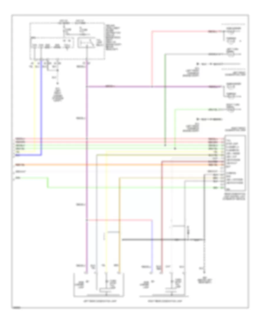
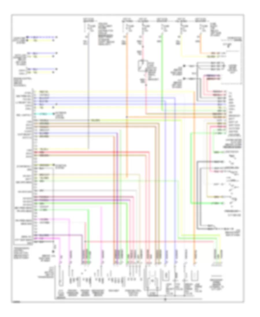
AIR CONDITIONING
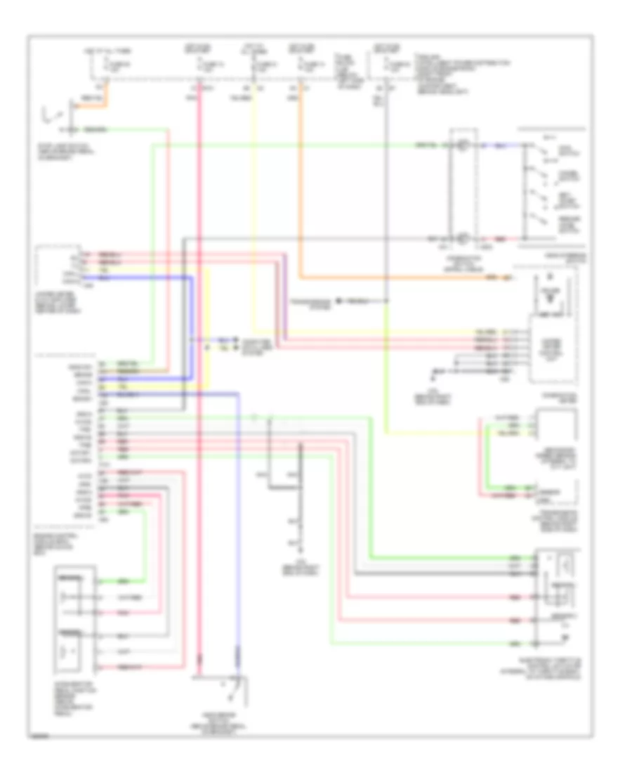
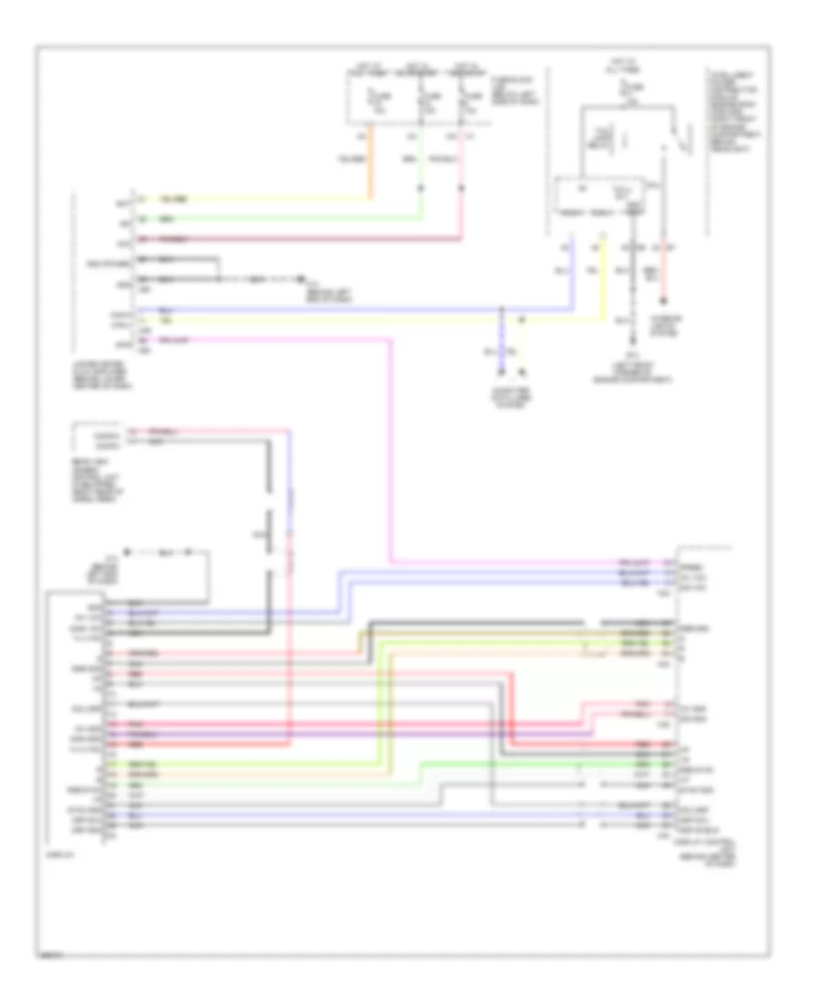
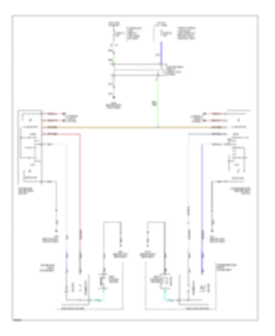
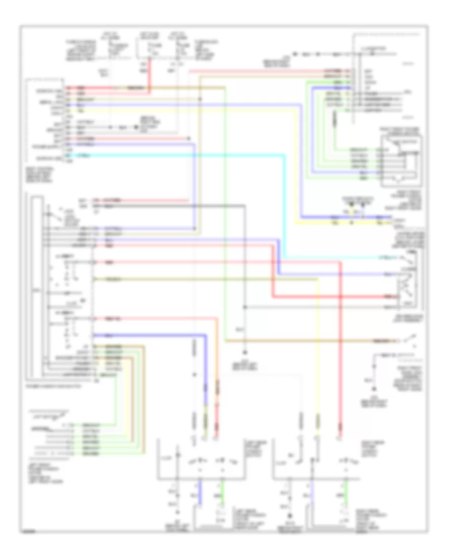
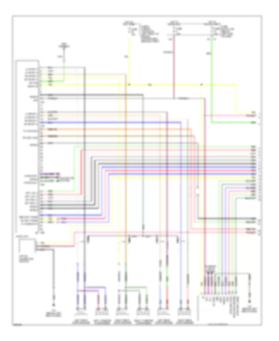
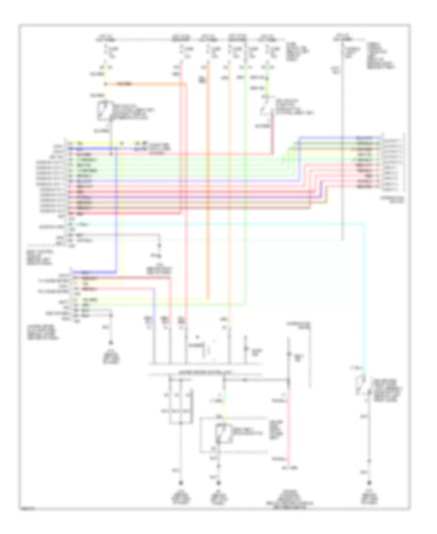
Automatic A/C Wiring Diagram (1 of 2) for Nissan Murano S 2007
 https://portal-diagnostov.com/license.html
Automotive Electricians Portal FZCO
Automotive Electricians Portal FZCO
https://portal-diagnostov.com/license.html
https://portal-diagnostov.com/license.html
Automotive Electricians Portal FZCO
Automotive Electricians Portal FZCO
List of elements for Automatic A/C Wiring Diagram (1 of 2) for Nissan Murano S 2007:
- (behind center of dash) display control unit
- (left front corner of engine compt) e13
- (power) gnd
- 12a
- A/c & av switch
- Acc
- Aircon sw
- Amb sens
- Ambient sensor (behind lower left side of front grille)
- Bat
- Blower fan sw
- Blower motor (behind lower right side of dash)
- Body control module (behind left side of dash)
- Bus shield
- Bus+
- Bus-
- Can-h
- Can-l
- Comp on
- Computer data lines system
- Dcu- dsp
- Dcu-dsp
- Display
- Driver side air mix door motor (behind lower left center of dash, on hvac assembly)
- Dsp gnd
- Dsp shield
- Dsp- dcu
- Dsp-dcu
- Fan on
- Fan pwm out
- Fuse 10a
- Fuse 15a
- Fuse block (j/b) (below left side of dash)
- Gnd
- Hot at all times
- Hot in acc or on
- Hot in on
- Hot in run or start
- Ign
- Ign2
- In-vehicle sensor (behind left center of dash)
- Incar sens
- Intake door motor (behind right side of dash, on hvac assembly)
- Intake sens
- Intake sensor (on evaporator unit)
- Lan sig
- M14 (behind left end of dash)
- M34
- M49
- M50
- M51
- M78 (behind right end of dash)
- Mode door motor (behind left center of dash, on hvac assembly)
- Nca
- Passenger side air mix door motor (behind lower right center of dash, on hvac assembly)
- Sens gnd
- Shield
- Sun sens
- Sunload sensor (on upper right side of dash, near base of windshield)
- Unified meter & a/c amplifier (behind lower center of dash)
- Vactr
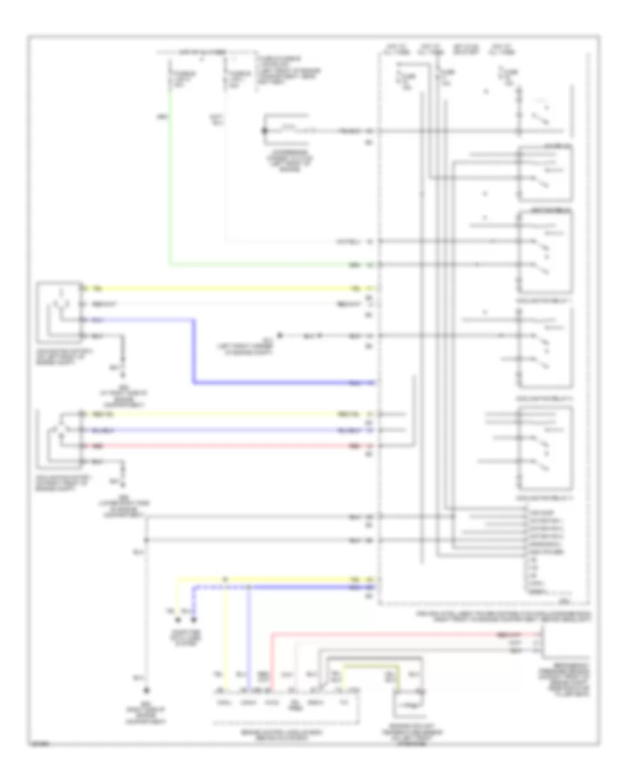
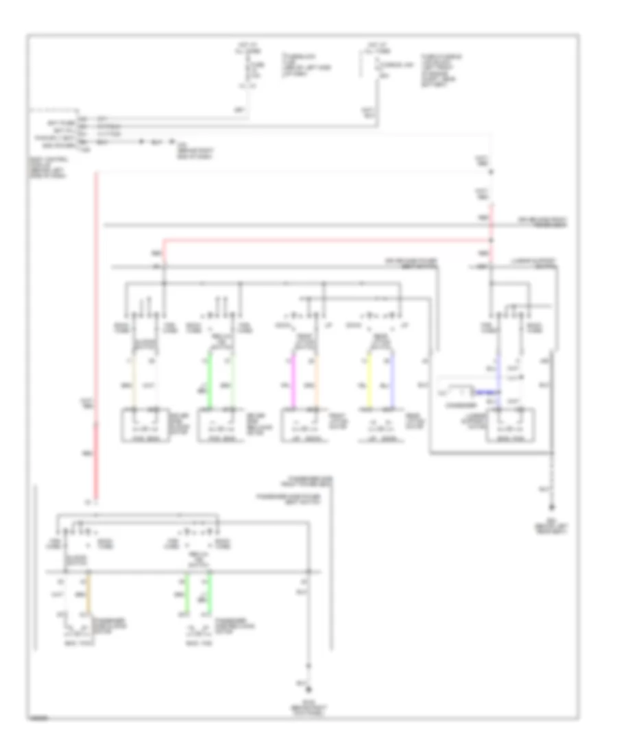
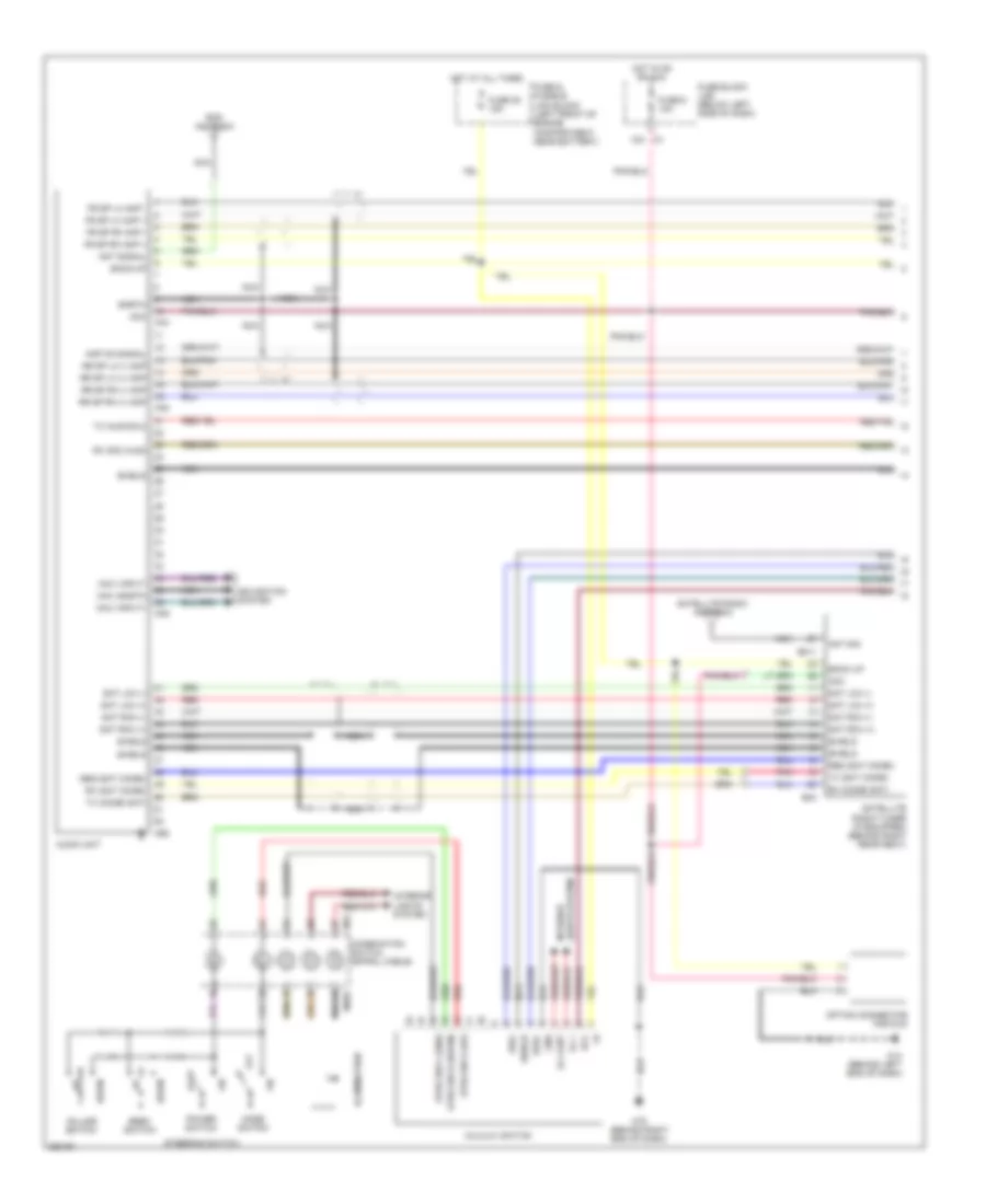
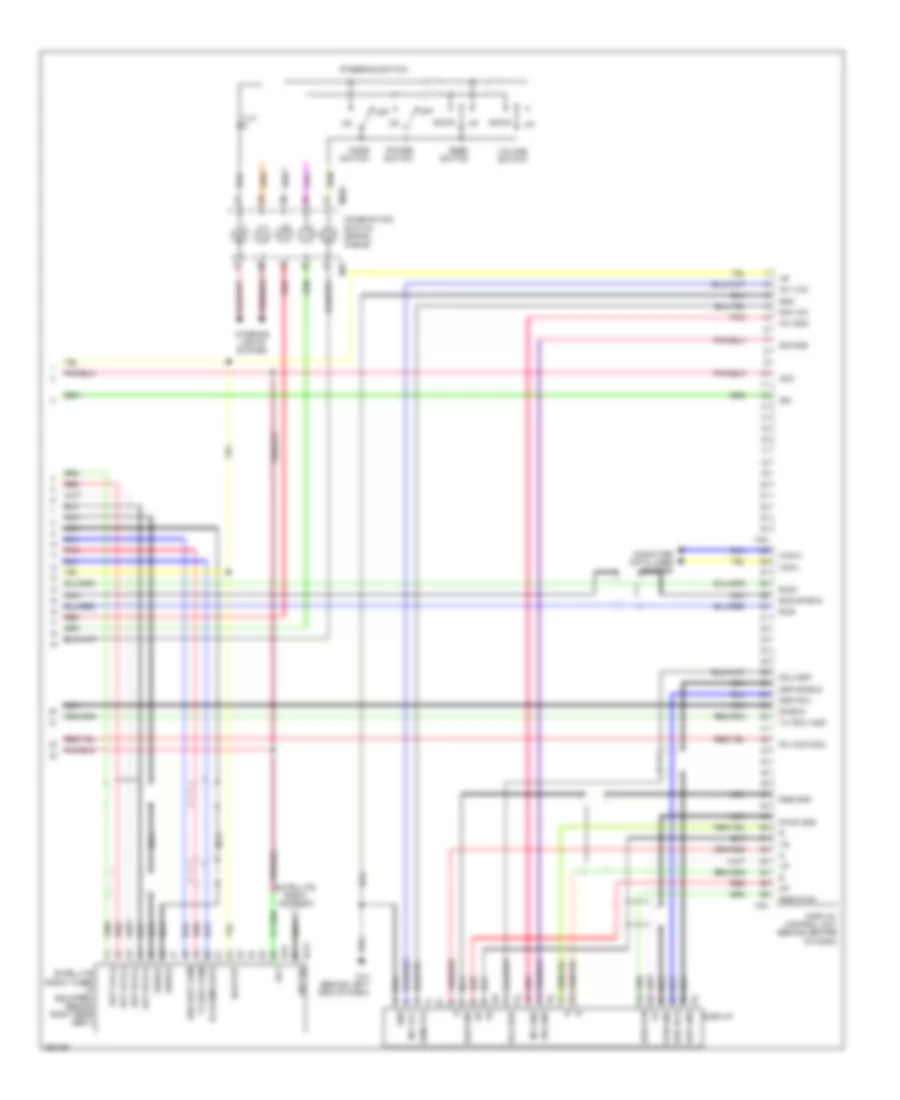
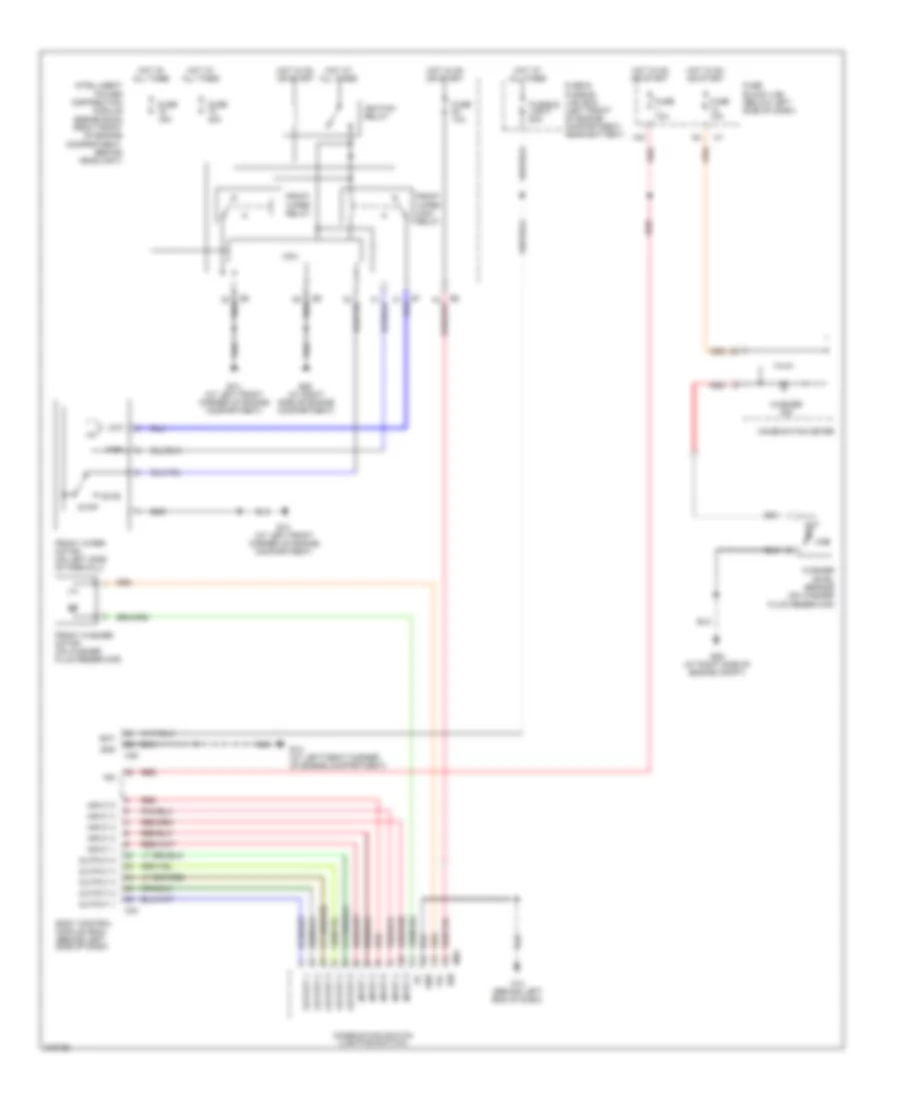
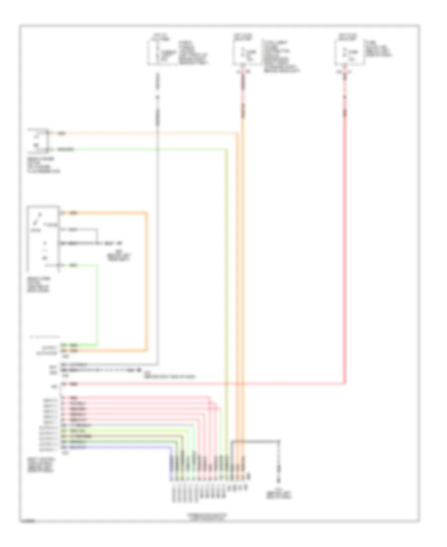
Automatic A/C Wiring Diagram (2 of 2) for Nissan Murano S 2007
List of elements for Automatic A/C Wiring Diagram (2 of 2) for Nissan Murano S 2007:
- +ig
- A/c relay
- Air comp
- Avcc
- Can-h
- Can-l
- Compressor (magnet clutch) (left front of engine)
- Computer data lines system
- Cooling fan motor 1 (on right front of engine compt)
- Cooling fan motor 2 (on left front of engine compt)
- Cooling fan relay 1
- Cooling fan relay 2
- Cooling fan relay 3
- Cpu
- E13 (left front corner of engine compt)
- E26 (lower right side of engine compartment)
- E28 (at right side of engine compartment)
- E28 (right side of engine compartment)
- Engine control module (ecm) (behind glove box)
- Engine coolant temperature sensor (on left front of engine)
- F101
- Fuse & fusible link block (left front of engine compartment, near battery)
- Fuse 10a
- Fuse 15a
- Fusible link k 40a
- Fusible link l 40a
- Gnd (power)
- Gnd(signal)
- Gnd-a
- Hot at all times
- Hot in on or start
- Ignition relay
- Ipdm e/r (intelligent power distribution module engine room) (right front of engine compartment, behind headlight)
- M80
- Motor fan 1
- Motor fan 2
- Motor fan 3
- Pd- pres
- Red
- Refrigerant pressure sensor (on right front of engine compt, near radiator filler neck)
ANTI-LOCK BRAKES
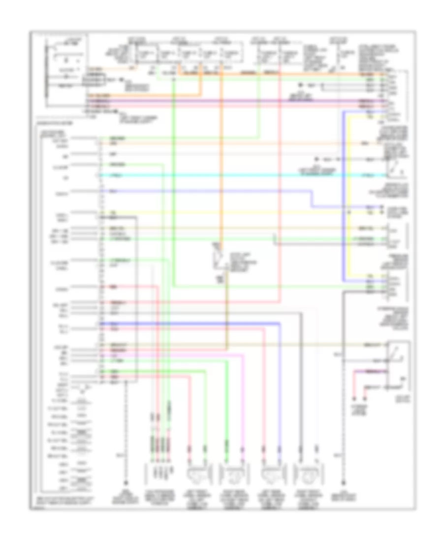
Anti-lock Brakes Wiring Diagram, with Traction Control for Nissan Murano S 2007
List of elements for Anti-lock Brakes Wiring Diagram, with Traction Control for Nissan Murano S 2007:
- Abs actuator & electric unit (right rear of engine compt)
- Abs ind
- Bat
- Brake fluid level switch (on master cylinder fluid reservoir)
- Brl
- Can-h
- Can-l
- Can1-h
- Can1-l
- Can2-h
- Can2-l
- Clus gnd
- Clus sp
- Combination meter
- Computer data lines system
- Data link connector (below left side of dash)
- Diag k
- Drv 1 gnd
- Drv 1 sig
- Drv 1 ss
- E101
- E13 (left front corner of engine compt)
- E26 (lower right side of engine compt)
- Fl (+)
- Fl (-)
- Fl in sol
- Fl out sol
- Fr (+)
- Fr (-)
- Fr in sol
- Fr out sol
- Fuse & fusible link block (left front of engine compt, near battery)
- Fuse 12 10a
- Fuse 14 10a
- Fuse 19 10a
- Fuse 20 10a
- Fuse 21 10a
- Fuse 82 10a
- Fuse block (j/b) (below left side of dash)
- Fusible link h 30a
- Fusible link j 50a
- Gnd
- Gnd p
- Gnd v
- Hot at all times
- Hot in on or start
- Hsv1
- Hsv2
- Ign
- Illum
- Intelligent power distribution module (engine room) (ipdm e/r) (right front of engine compt, behind headlight)
- Interior lights system
- Left front wheel sensor (on left wheel hub assembly)
- Left rear wheel sensor (on left rear wheel hub assembly)
- Lis
- M14 (behnd left end of dash)
- M25
- M49
- M50
- M78 (behind right end of dash)
- M78 (behnd right end of dash)
- Mot (+)
- Mot (-)
- Mot bat
- Pnk
- Pressure sensor (left rear of engine compt)
- Red
- Right front wheel sensor (on right wheel hub assembly)
- Right rear wheel sensor (on right rear wheel hub assembly)
- Rl (+)
- Rl (-)
- Rl in sol
- Rl out sol
- Rr (-)
- Rr +
- Rr in sol
- Rr out sol
- Slip ind
- Sol bat
- Steering angle sensor (below left side of dash, near steering column)
- Stop lamp switch (above brake pedal, on bracket)
- Unified meter & a/c amplifier (behind lower center of dash)
- Unified meter control unit
- Usv1
- Usv2
- V out
- Vcc
- Vdc off
- Vdc off ind
- Vdc off switch
- Vdc/tcs/abs control unit
- Yaw rate/side/ decel g sensor (below center console)
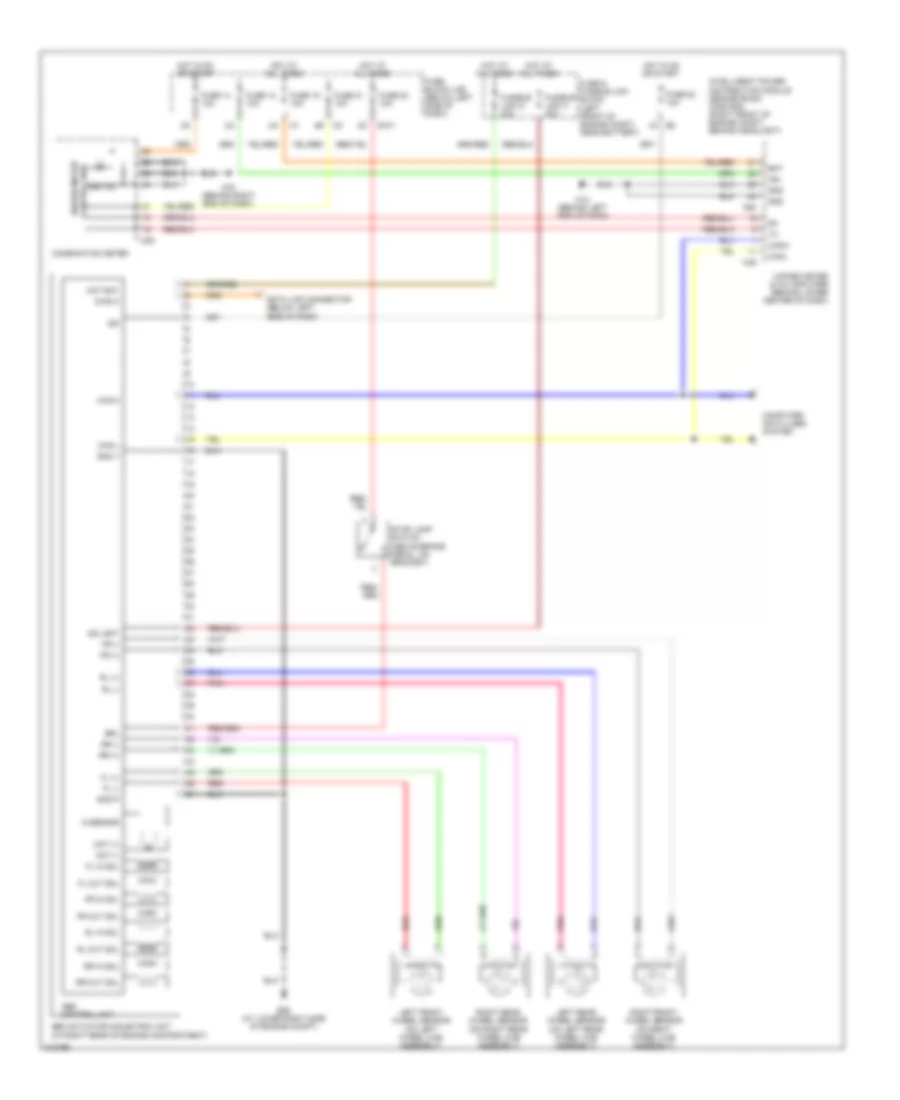
Anti-lock Brakes Wiring Diagram, without Traction Control for Nissan Murano S 2007
List of elements for Anti-lock Brakes Wiring Diagram, without Traction Control for Nissan Murano S 2007:
- Abs actuator & electric unit (at right rear of engine compartment)
- Abs control unit
- Abs ind
- Bat
- Brl
- Can-h
- Can-l
- Combination meter
- Computer data lines system
- Control unit
- Data link connector (below left side of dash)
- Diag k
- E101
- E26 (at lower right side of engine compt)
- Fl (+)
- Fl (-)
- Fl in sol
- Fl out sol
- Fr (+)
- Fr (-)
- Fr in sol
- Fr out sol
- Fuse & fusible link block (left front of engine compt, near battery)
- Fuse 12 10a
- Fuse 14 10a
- Fuse 19 10a
- Fuse 20 10a
- Fuse 21 10a
- Fuse 82 10a
- Fuse block (j/b) (below left side of dash)
- Fusible link g 30a
- Fusible link h 30a
- G sensor
- Gnd
- Gnd p
- Gnd v
- Hot at all times
- Hot in on or start
- Ign
- Intelligent power distribution module (engine room) (ipdm e/r) (right front of engine compt, behind headlight)
- Left front wheel sensor (on left wheel hub assembly)
- Left rear wheel sensor (on left rear wheel hub assembly)
- M14 (behind left end of dash)
- M25
- M49
- M50
- M78 (behind right end of dash)
- Mot (+)
- Mot (-)
- Mot bat
- Pnk
- Red
- Right front wheel sensor (on right wheel hub assembly)
- Right rear wheel sensor (on right rear wheel hub assembly)
- Rl (+)
- Rl (-)
- Rl in sol
- Rl out sol
- Rr (+)
- Rr (-)
- Rr in sol
- Rr out sol
- Sol bat
- Stop lamp switch (above brake pedal, on bracket)
- Unified meter
- Unified meter & a/c amplifier (behind lower center of dash)
ANTI-THEFT
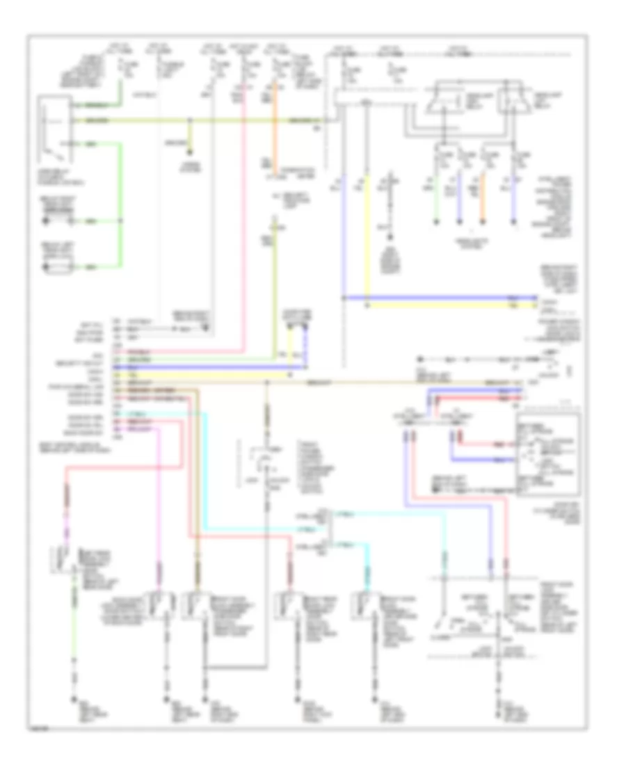
Forced Entry Wiring Diagram for Nissan Murano S 2007
List of elements for Forced Entry Wiring Diagram for Nissan Murano S 2007:
- (behind left end of dash) m14
- (behind right end of dash) m78
- (behind right side of dash) (if equipped) intelligent key unit
- (below left headlight) horn (low)
- (below right headlight) horn (high)
- (or red)
- 12a m1
- 4b m2
- Acc
- B105 (behind right kick panel)
- B20 (behind left rear seat)
- Back door lock assembly (door switch) (lower center of back door)
- Back door sw
- Bat (f/l)
- Bat (fuse)
- Between full stroke & n
- Body control module (behind left side of dash)
- Can-h
- Can-l
- Closed
- Com
- Combination meter
- Computer data lines system
- Cpu
- Door key cylinder switch (in driver's door)
- Door sw (as)
- Door sw (dr)
- Door sw (rl)
- Door sw (rr)
- E28 (right side of engine compt)
- Front door lock assembly (driver side door key cylinder switch) (rear of left front door)
- Front door lock assembly (driver side door switch) (rear of left front door)
- Front door lock assembly (passenger side door switch) (rear of right front door)
- Front power window switch (passenger side door lock & unlock switch)
- Full stroke
- Full stroke unlock switch
- Fuse & fusible link block (left front of engine compt, near battery)
- Fuse 10a
- Fuse 15a
- Fuse block (j/b) (below left side of dash)
- Fusible link f 50a
- Gnd
- Gnd (pwr)
- Headlamp high relay
- Headlamp low relay
- Headlights system
- Horn relay (in fuse & fusible link box)
- Horns system
- Hot at all times
- Hot in acc or on
- Intelligent power distribution module engine room (ipdm e/r) (right front of engine compt, behind headlight)
- Left rear door lock assembly (door switch) (rear of left rear door)
- Lock
- Lock switch
- Lock switch full stroke
- M14 (behind left end of dash)
- M25
- M34
- M35
- M36
- M78 (behind right end of dash)
- Open
- Power window main switch (door lock & unlock switch)
- Pwr win serial link
- Red
- Right rear door lock assembly (door switch) (rear of right rear door)
- Security ind out
- Security indicator lamp
- Unlock
- Unlock switch
- W/ intelligent key
- W/o intelligent key
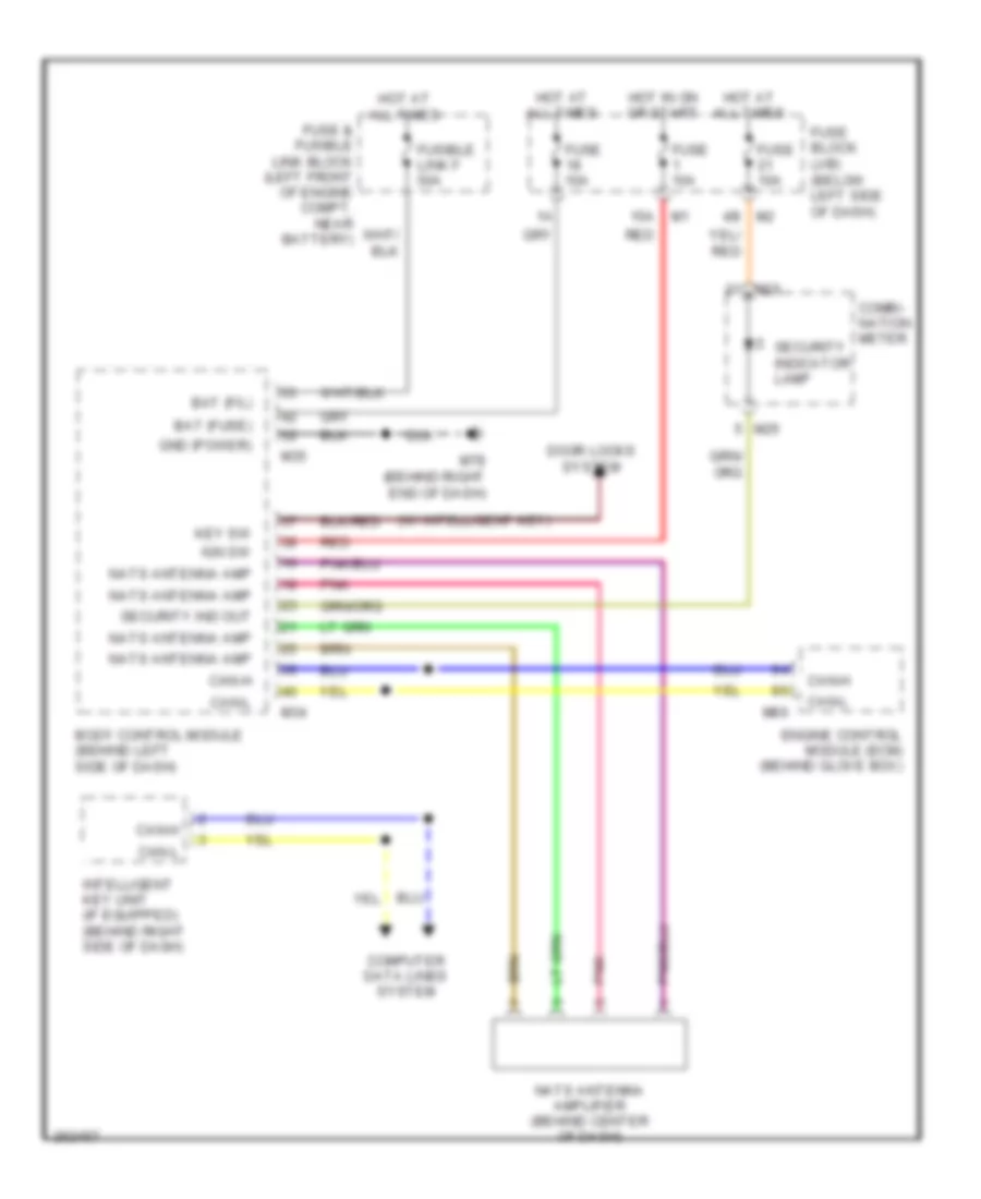
Immobilizer Wiring Diagram for Nissan Murano S 2007
List of elements for Immobilizer Wiring Diagram for Nissan Murano S 2007:
- (w/ intelligent key)
- 15a m1
- 4b m2
- Bat (f/l)
- Bat (fuse)
- Body control module (behind left side of dash)
- Can-h
- Can-l
- Combi- nation meter
- Computer data lines system
- Door locks system
- Engine control module (ecm) (behind glove box)
- Fuse & fusible link block (left front of engine compt, near battery)
- Fuse 10a
- Fuse block (j/b) (below left side of dash)
- Fusible link f 50a
- Gnd (power)
- Hot at all times
- Hot in on or start
- Ign sw
- Intelligent key unit (if equipped) (behind right side of dash)
- Key sw
- M25
- M34
- M35
- M78 (behind right end of dash)
- M80
- Nats antenna amp
- Nats antenna amplifier (behind center of dash)
- Pnk
- Red
- Security ind out
- Security indicator lamp
BODY CONTROL MODULES
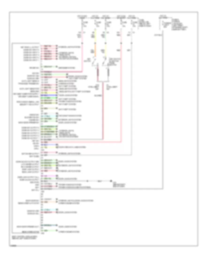
Body Control Modules Wiring Diagram for Nissan Murano S 2007
List of elements for Body Control Modules Wiring Diagram for Nissan Murano S 2007:
- 12a
- 15a
- 1b m2
- Acc sw
- Air conditioning system
- Aircon sw
- Anti-theft system
- Auto light sens in
- Auto light sens pwr
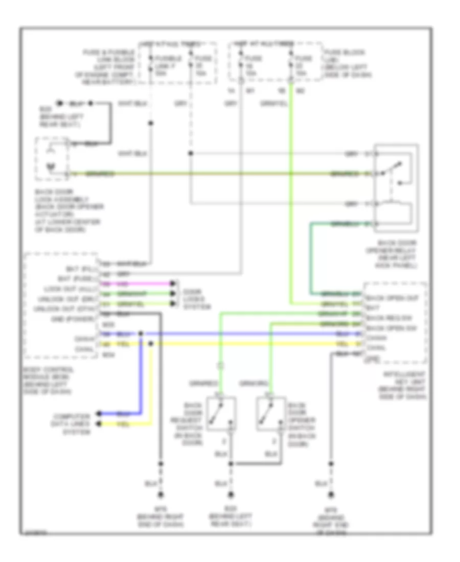
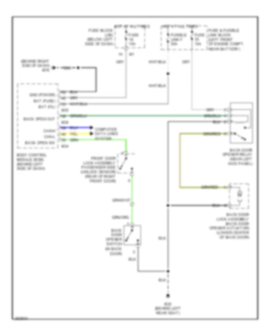
- Back door opener (out)
- Back door opener sw
- Back door sw
- Bat
- Bat (f/l)
- Bat (fuse)
- Bat saver output
- Blower fan sw
- Body control module (bcm) (behind left side of dash)
- Can-h
- Can-l
- Combi sw input 1
- Combi sw input 2
- Combi sw input 3
- Combi sw input 4
- Combi sw input 5
- Combi sw output 1
- Combi sw output 2
- Combi sw output 3
- Combi sw output 4
- Combi sw output 5
- Computer data lines system
- Defogger system
- Door lock output (all)
- Door locks system
- Door locks system anti-theft system
- Door sw (as)
- Door sw (dr)
- Door sw (rl)
- Door sw (rr)
- Door unlock output
- Door unlock output (dr)
- Exterior lights system
- Fuse & fusible link block (left front of engine compt, near battery)
- Fuse 10a
- Fuse block (j/b) (below left side of dash)
- Fusible link f 50a
- Gnd (pwr)
- Hazard sw
- Headlights & anti-theft systems
- Headlights system
- Hot at all times
- Hot in acc or on
- Hot in on or start
- Ign sw
- Interior lights & door locks system
- Interior lights system
- Interior lights, headlights, exterior lights & navigation systems
- Key ring ill output
- Key sw
- Key switch
- Key switch & ignition knob switch
- Keyless tuner signal
- Lh flasher output
- M34
- M35
- M36
- M78 (behind right end of dash)
- Pnk
- Power windows & seats systems
- Power windows system
- Pwr window serial link
- Rap
- Rear wiper auto stop
- Rear wiper motor
- Red
- Rh flasher output
- Room lamp output
- Rr def sw
- Security ind output
- Sens gnd
- Step lamp output
- Tpms mode trigger sw
- W/ intelligent key
- W/o intelligent key
- Warning system
- Wiper/washer system
COMPUTER DATA LINES
Computer Data Lines Wiring Diagram for Nissan Murano S 2007
List of elements for Computer Data Lines Wiring Diagram for Nissan Murano S 2007:
- (behind center of dash) display control unit
- (behind left end of dash) m14
- A/c & av switch
- Abs actuator & electric unit (control unit) (right rear of engine compt)
- Air bag diagnosis sensor unit (below center console, between seats)
- Audio unit
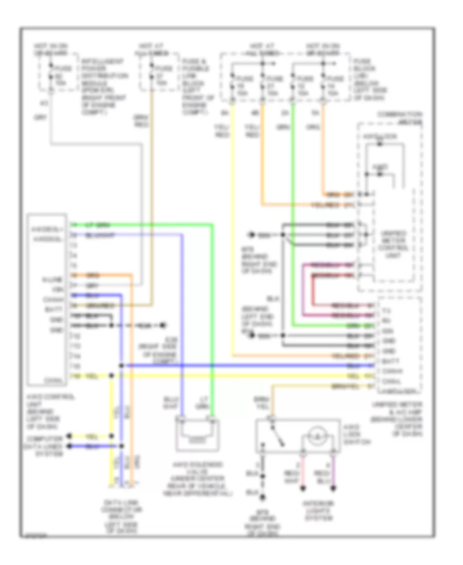
- Awd control unit (awd models) (behind left side of dash)
- Body control module (behind left side of dash)
- Bus +
- Bus -
- Bus shield
- Can-h
- Can-l
- Can2-h
- Can2-l
- Com
- Combination meter
- Cpu
- Data link connector (below left side of dash)
- Ddl
- Diag-k
- Driver seat control unit (w/ automatic driver positioner) (under driver seat)
- Engine control module (ecm) (behind glove box)
- F103
- Front power window switch (passenger side) (door lock & unlock switch)
- Fuse 12 10a
- Fuse 19 10a
- Fuse block (j/b) (below left side of dash)
- Hot at all times
- Hot in on or start
- Intelligent key unit (if equipped) (behind right side of dash)
- Intelligent power distribution module engine room (ipdm e/r) (right front of engine compt, behind headlight)
- K-line
- M34
- M43
- M46
- M49
- M63
- M64
- M80
- M99
- Navi control unit (under front of center console)
- Nca
- Option connector
- Power window main switch (door lock & unlock switch)
- Pwr wdo serial link
- Rear view camera control unit (if equipped) (right rear of cargo area)
- Red
- Rx (aud-dcu)
- Rx (comb meter)
- Shield
- Steering angle sensor (w/ vdc) (below left side of dash, near steering column)
- Transmission control module (behind right side of dash)
- Tx (comb meter)
- Tx (dcu-aud)
- Unified meter & a/c amplifier (behind lower center of dash)
- Unified meter control unit
- Vdc/tcs/abs control unit
- W/ navigation
- W/o navigation
- Yaw rate/side/ decel g sensor (below center console)
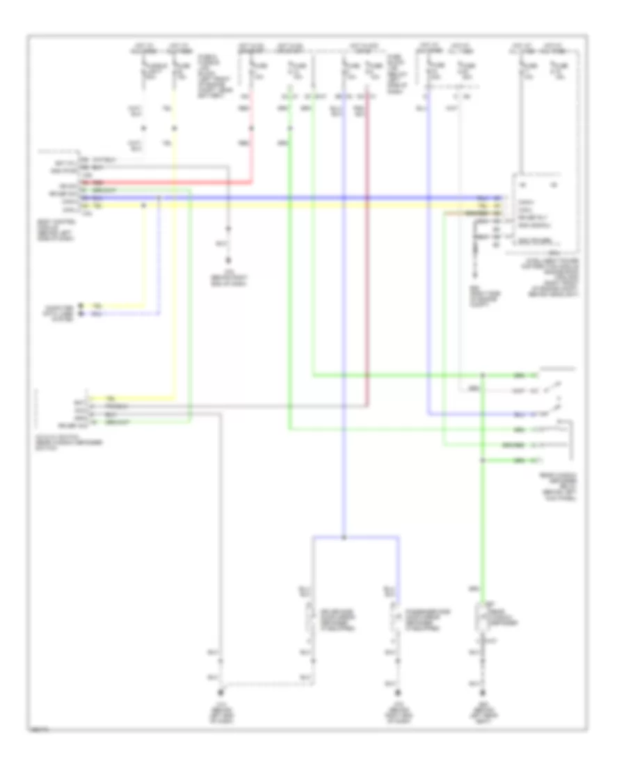
COOLING FAN
Cooling Fan Wiring Diagram for Nissan Murano S 2007
List of elements for Cooling Fan Wiring Diagram for Nissan Murano S 2007:
- (left front corner of engine compartment) e13
- (right front of engine compt, behind headlight) intelligent power distribution module (engine room) (ipdm e/r)
- +ig
- Can-h
- Can-l
- Computer data lines system
- Cooling fan motor 1 (on right front of engine compartment)
- Cooling fan motor 2 (on left front of engine compartment)
- Cooling fan relay 1
- Cooling fan relay 2
- Cooling fan relay 3
- Cpu
- E26 (lower right side of engine compartment)
- E28 (right side of engine compt)
- Engine control module (ecm) (behind glove box)
- Engine coolant temperature sensor (on left front of engine)
- F101
- Fuse & fusible link block (left front of engine compt, near battery)
- Fuse 10a
- Fuse 15a
- Fusible link k 40a
- Fusible link l 40a
- Gnd (power)
- Gnd (sig)
- Gnd-a
- Hot at all times
- Hot in on or start
- Ignition relay
- M80
- Motor fan-1
- Motor fan-2
- Motor fan-3
- Red
CRUISE CONTROL
Cruise Control Wiring Diagram for Nissan Murano S 2007
List of elements for Cruise Control Wiring Diagram for Nissan Murano S 2007:
- Accelerator pedal position sensor (above accelerator pedal)
- Aps1
- Aps2
- Ascd brake switch (above brake pedal, on bracket)
- Ascd steering switch
- Ascd sw
- Avcc
- Avcc2
- Bncsw
- Brake
- Can-h
- Can-l
- Cancel switch
- Combination meter
- Combination switch (spiral cable)
- Computer data lines system
- Cruise ind
- E101 1c
- Electronic throttle control actuator (integral to throttle body, on intake manifold)
- Engine control module (ecm) (behind glove box)
- F101
- Fuse 12 10a
- Fuse 14 10a
- Fuse 20 10a
- Fuse 21 10a
- Fuse 83 10a
- Fuse block (j/b) (below left side of dash)
- Gnd
- Gnd-a
- Gnd-a2
- Gns-a
- Hot at all times
- Hot in on or start
- Ipdm e/r (intelligent power distribution module engine room) (right front of engine compartment, behind headlight)
- M203
- M25
- M31
- M49
- M78 (behind right end of dash)
- M80
- Main switch
- Motor 1
- Motor 2
- Nca
- Pnk
- Red
- Resume/ accel switch
- Secondary speed sensor (integral to cvt unit)
- Sensor
- Sensor 1
- Sensor 2
- Set ind
- Set/ coast switch
- Stop lamp switch (above brake pedal, on bracket)
- Tps1
- Tps2
- Transmission control module (behind right side of dash)
- Transmissions system
- Unified meter & a/c amplifier (behind lower center of dash)
- Unified meter control unit
DEFOGGERS
Defoggers Wiring Diagram for Nissan Murano S 2007
List of elements for Defoggers Wiring Diagram for Nissan Murano S 2007:
- (below left side of dash)
- 15a
- 2c e101
- 5b m2
- A/c & av switch (rear window defogger switch)
- Acc
- B20 (behind left rear seat)
- Bat
- Bat (f/l)
- Body control module (behind left side of dash)
- Can-h
- Can-l
- Computer data lines system
- Cpu
- D107
- D97
- Driver side door mirror defogger (if equipped)
- E28 (right side of engine compt)
- Fuse & fusible link block (left front of engine compt, near battery)
- Fuse 10a
- Fuse 15a
- Fuse 20a
- Fuse block (j/b)
- Fusible link f 50a
- Gnd
- Gnd (power)
- Gnd (pwr)
- Gnd (signal)
- Hot at all times
- Hot in acc or on
- Hot in on or start
- Ign sw
- Intelligent power distribution module engine room (ipdm e/r) (right front of engine compt, behind headlight)
- M1 12a
- M14 (behind left end of dash)
- M34
- M35
- M78 (behind right end of dash)
- Passenger side door mirror defogger (if equipped)
- Rear window defogger
- Rear window defogger relay (behind left kick panel)
- Red
- Rr def on
- Rr def rly
- Rr def sw
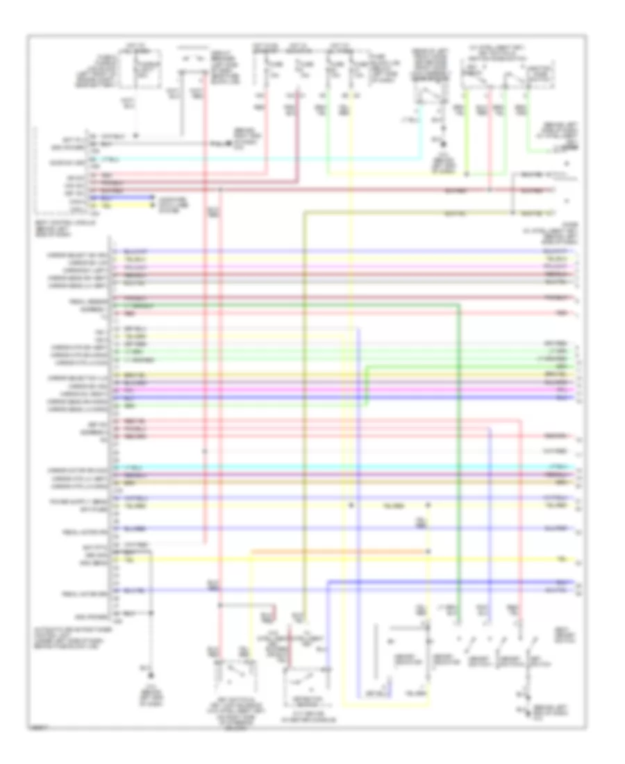
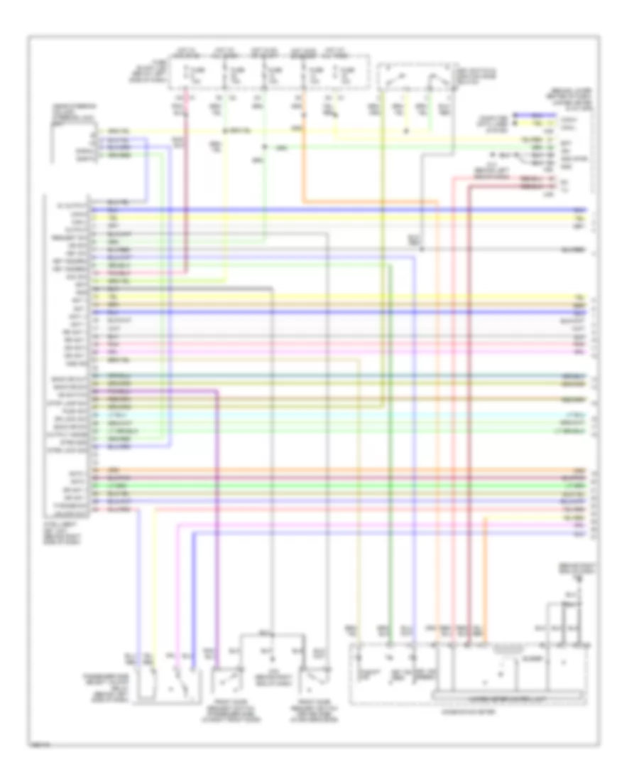
ENGINE PERFORMANCE
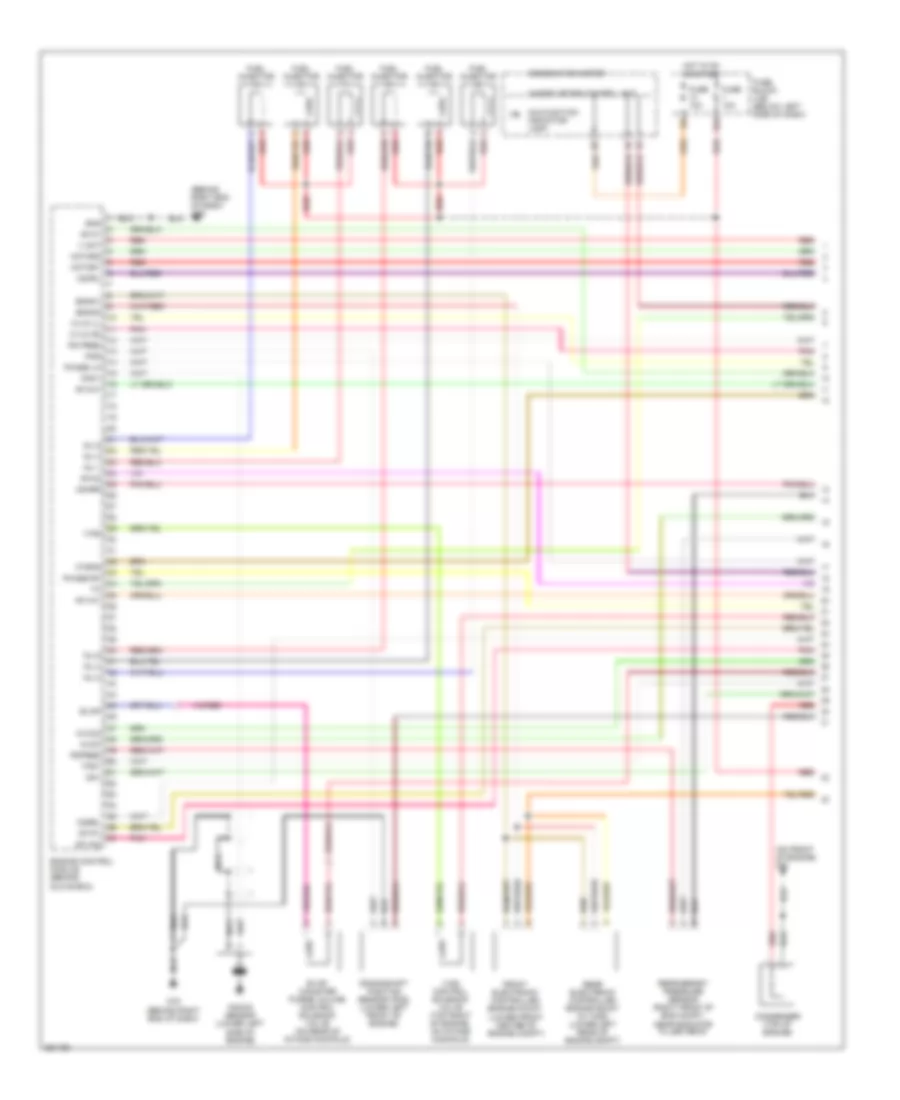
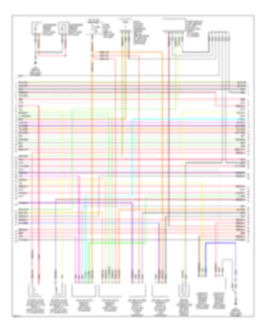
3.5L
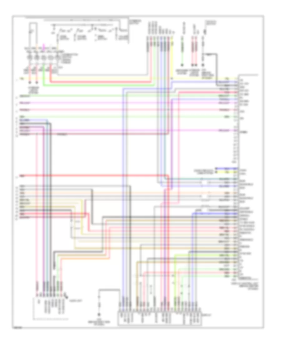
3.5L, Engine Performance Wiring Diagram (1 of 4) for Nissan Murano S 2007
List of elements for 3.5L, Engine Performance Wiring Diagram (1 of 4) for Nissan Murano S 2007:
- (behind right end of dash)
- (on front of engine) f23
- 15a
- Af-h1
- Af-h2
- Af-ip1
- Af-un1
- Af-vm1
- Af-vm2
- Avcc
- Avcc2
- C-ivc (l)
- C-ivc (r)
- Combination meter
- Condenser (top of engine)
- Crankshaft position sensor (pos) (lower left front of engine)
- Engine control module (behind glove box)
- Enmn1
- Enmn2
- Evap
- Evap canister purge volume control solenoid valve (on rear of intake manifold)
- Front electronic controlled engine mount (lower front center of engine compt)
- Ftrps
- Fuel injector
- Fuse 10a
- Fuse block (j/b) (below left side of dash)
- Gnd
- Hot in on or start
- Inj 1
- Inj 2
- Inj 3
- Inj 4
- Inj 5
- Inj 6
- Knk1
- Knock sensor (lower left side of engine)
- M78
- M78 (behind right end of dash)
- Malfunction indicator lamp
- Motor1
- Motor2
- Nca
- O2hrl
- O2hrr
- O2srl
- Pdpres
- Phase lh
- Phase rh
- Pnk
- Pos
- Ps pres
- Qa+
- Rear electronic controlled engine mount (w/ awd) (lower left rear of engine compt)
- Red
- Refrigerant pressure sensor (right front of eng compt, near radiator filler neck)
- Tps1
- Unified meter control unit
- V mot
- Vias
- Vias control solenoid valve (top right of engine, on intake manifold)
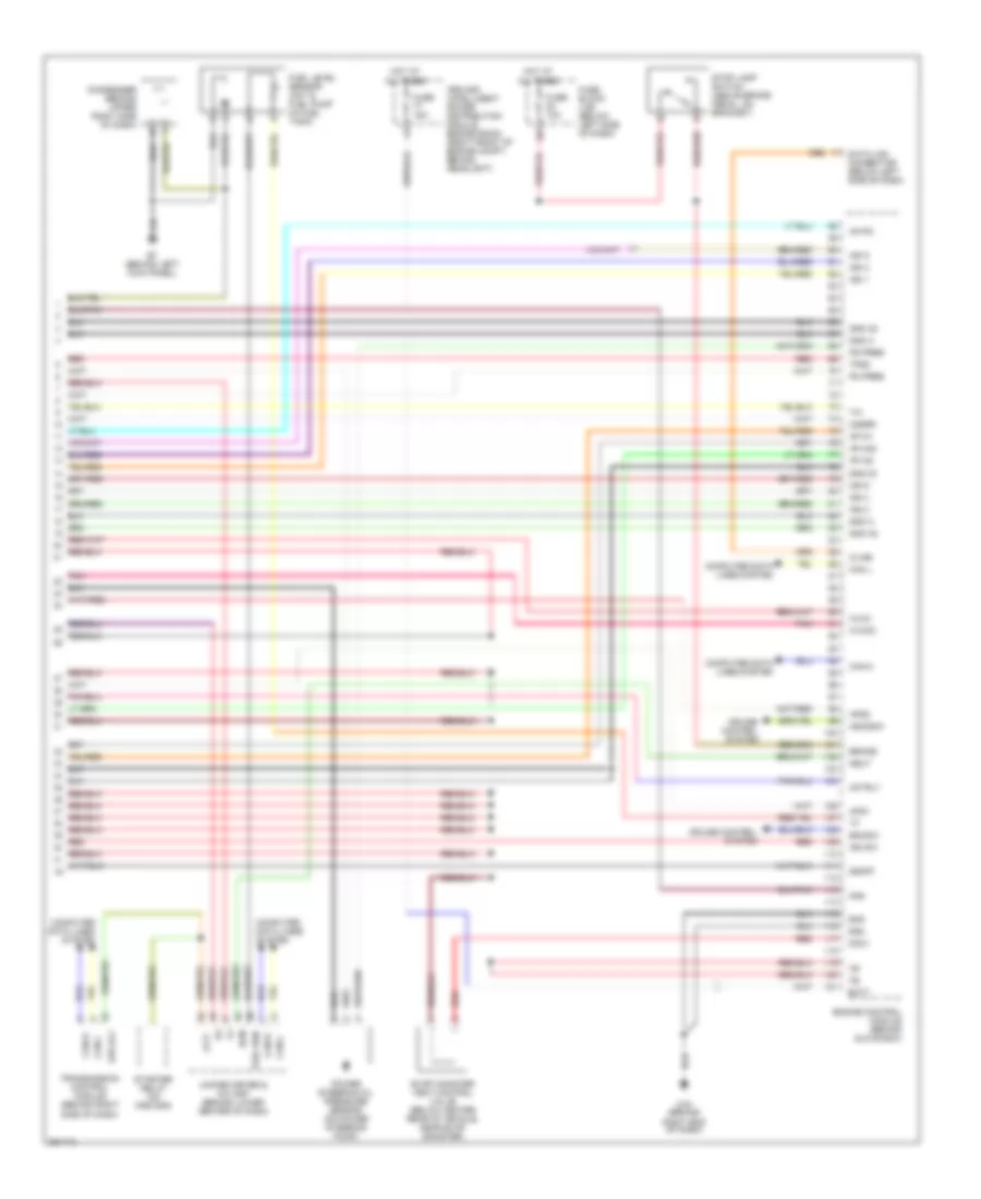
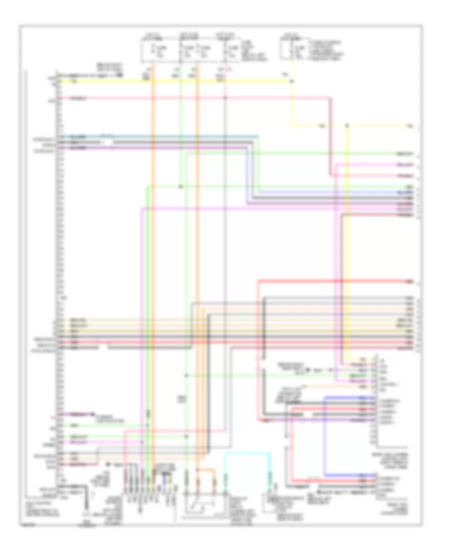
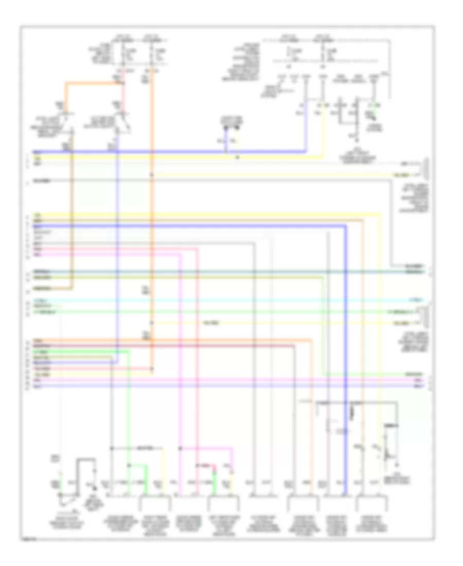
3.5L, Engine Performance Wiring Diagram (2 of 4) for Nissan Murano S 2007
List of elements for 3.5L, Engine Performance Wiring Diagram (2 of 4) for Nissan Murano S 2007:
- (on front of engine) f23
- Accelerator pedal position sensor (above accelerator pedal)
- Ecm relay
- Electric throttle control actuator (integral with throttle body, on intake manifold)
- F33
- Fuel pump relay
- Fuse 10a
- Fuse 15a
- Fuse block (j/b) (below left side of dash)
- Hot at all times
- Hot in on or start
- Ignition coil 1 (w/ power transistor)
- Ignition coil 2 (w/ power transistor)
- Ignition coil 3 (w/ power transistor)
- Ignition coil 4 (w/ power transistor)
- Ignition coil 5 (w/ power transistor)
- Ignition coil 6 (w/ power transistor)
- Ipdm e/r (intelligent power distribution module engine room) (right front of engine compt, behind headlight)
- M67
- M78 (behind right end of dash)
- Nca
- Nca nca
- Plug spark
- Pnk
- Red
- Sensor 1
- Sensor 2
- Spark plug
- Throttle control motor
- Throttle control motor relay
- Throttle position (tp) sensor 1
- Throttle position (tp) sensor 2
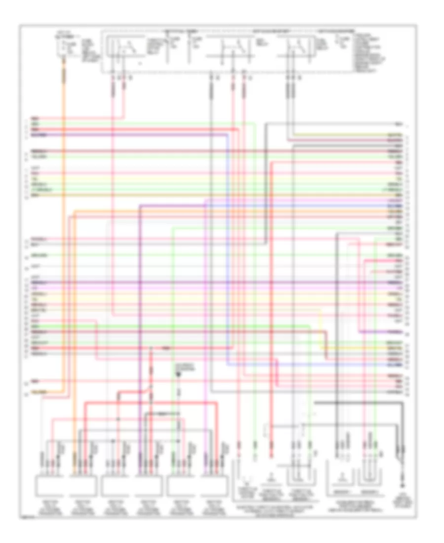
3.5L, Engine Performance Wiring Diagram (3 of 4) for Nissan Murano S 2007
List of elements for 3.5L, Engine Performance Wiring Diagram (3 of 4) for Nissan Murano S 2007:
- Air fuel ratio sensor 1 (bank 1) (right front of engine)
- Air fuel ratio sensor 1 (bank 2) (left front of engine)
- Camshaft position sensor (phase) (bank 1) (right rear of engine)
- Camshaft position sensor (phase) (bank 2) (left rear of engine)
- Condenser (behind upper right side of dash)
- Engine coolant temperature sensor (on left front of engine)
- Evap control system pressure sensor (below center rear of vehicle, near evap canister)
- Fuse 15a
- Fuse block (j/b) (below left side of dash)
- Heated oxygen sensor 2 (bank 1) (on outlet of rear twc) (manifold)
- Heated oxygen sensor 2 (bank 2) (on outlet of front twc) (manifold)
- Hot in on or start
- Intake valve timing control solenoid valve (bank 1) (front of right cylinder bank)
- Intake valve timing control solenoid valve (bank 2) (front of left cylinder bank)
- M78 (behind right end of dash)
- Mass airflow (maf) sensor (on left side of eng compt, attached to air box)
- Pnk
- Red
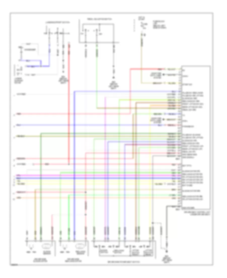
3.5L, Engine Performance Wiring Diagram (4 of 4) for Nissan Murano S 2007
List of elements for 3.5L, Engine Performance Wiring Diagram (4 of 4) for Nissan Murano S 2007:
- Af-ia1
- Af-ia2
- Af-ip2
- Af-un2
- Aps1
- Aps2
- Ascdsw
- At-p
- Avcc
- Avcc2
- B7 (behind left kick panel)
- Batt
- Bncsw
- Brake
- Can l
- Can-h
- Can-l
- Cdcv
- Computer data lines system
- Condenser (behind upper right side of dash)
- Cruise control system
- Data link connector (below left side of dash)
- Ecm
- Engine control module (behind glove box)
- Evap canister vent control valve (below center rear of vehicle, near evap canister)
- Fpr
- Fuel level sensor unit & fuel pump (in fuel tank)
- Fuel sen
- Fuse 10a
- Fuse 15a
- Fuse block (j/b) (below left side of dash)
- Gnd
- Gnd 02
- Gnd a
- Gnd a2
- Hot at all times
- Ign 1
- Ign 2
- Ign 3
- Ign 4
- Ign 5
- Ign 6
- Ign sw
- Ipdm e/r (intelligent power distribution module engine room) (right front of engine compt, behind headlight)
- Kline
- M78 (behind right end of dash)
- Moyrly
- Neut
- O2srr
- Pd pres
- Pnk
- Power steering oil pressure sensor (on power steering pump)
- Ps pres
- Red
- Ssoff
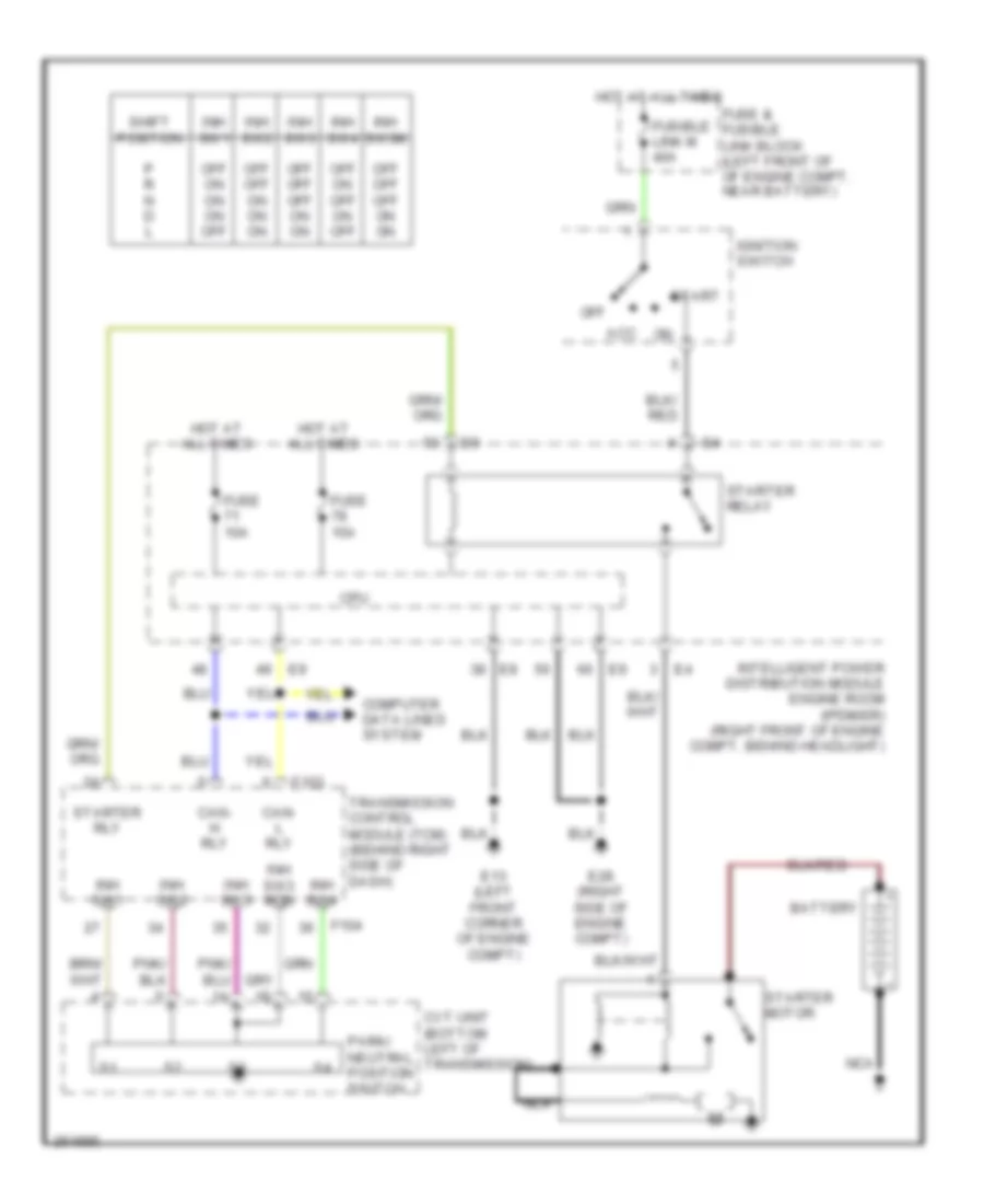
- Starter relay (on ipdm e/r)
- Stop lamp switch (above brake pedal, on bracket)
- Str rly
- Tps2
- Transmission control module (behind right side of dash)
- Unified meter & a/c amp (behind lower center of dash)
EXTERIOR LIGHTS
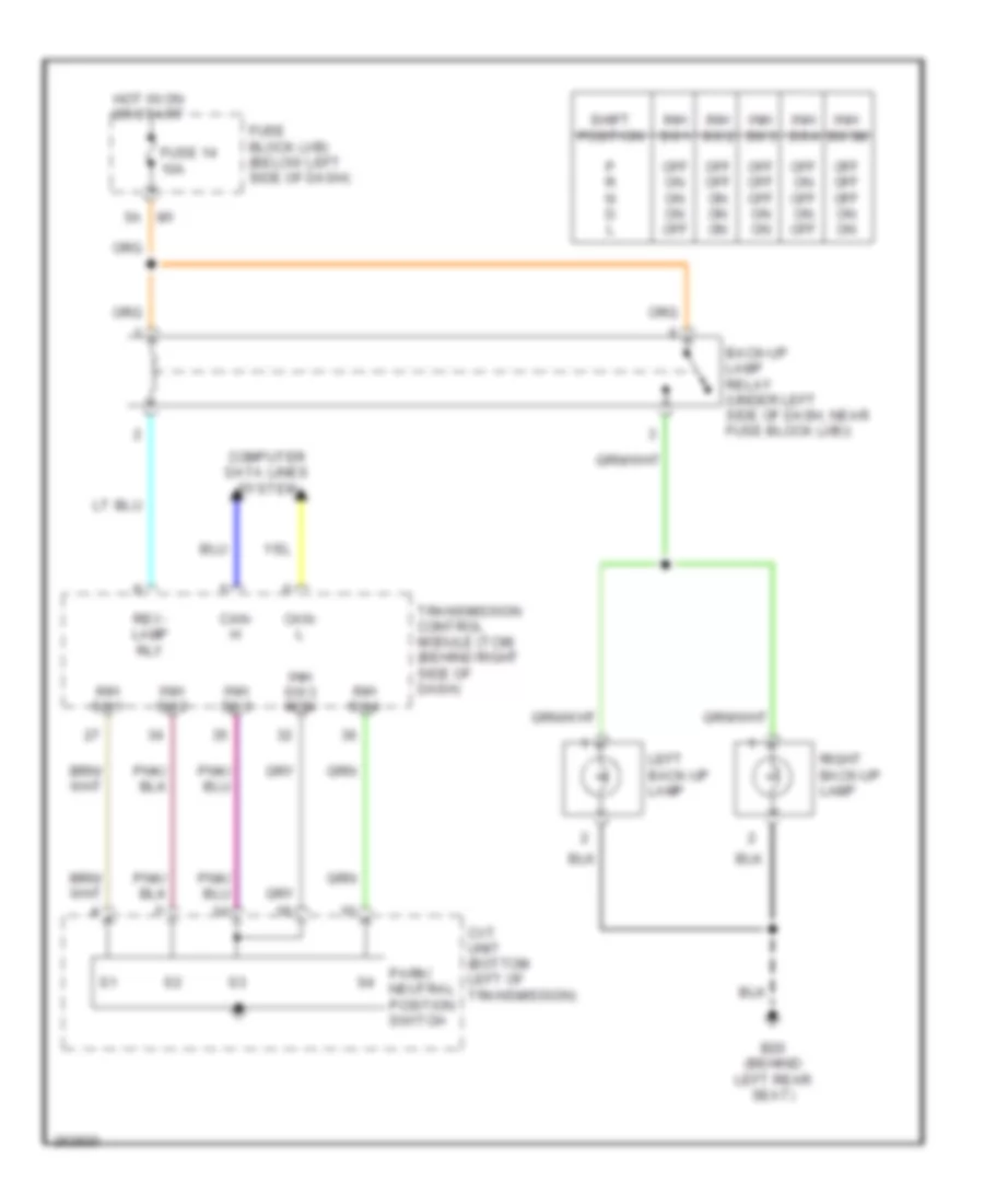
Back-up Lamps Wiring Diagram for Nissan Murano S 2007
List of elements for Back-up Lamps Wiring Diagram for Nissan Murano S 2007:
- B20 (behind left rear seat)
- Back-up lamp relay (under left side of dash, near fuse block (j/b))
- Can- h
- Can- l
- Computer data lines system
- Cvt unit (bottom left of transmission)
- Fuse 14 10a
- Fuse block (j/b) (below left side of dash)
- Hot in on or start
- Inh sw1
- Inh sw2
- Inh sw3
- Inh sw3 mon
- Inh sw3m
- Inh sw4
- Left back-up lamp
- Off off off on on
- Off off on on on
- Off on off on off
- Off on on on off
- P r n d l
- Park/ neutral position switch
- Rev- lamp rly
- Right back-up lamp
- Shift position
- Transmission control module (tcm) (behind right side of dash)
Exterior Lamps Wiring Diagram (1 of 2) for Nissan Murano S 2007
List of elements for Exterior Lamps Wiring Diagram (1 of 2) for Nissan Murano S 2007:
- (behind right end of dash) m78
- (below left side of dash)
- 12a
- 15a
- 8c e101
- Acc
- B20 (behind left rear seat)
- Bat
- Batt
- Body control module (bcm) (behind left side of dash)
- Brake sw
- Buzzer
- Can-h
- Can-l
- Comb sw in 1
- Comb sw in 2
- Comb sw in 3
- Comb sw in 4
- Comb sw in 5
- Comb sw out 1
- Comb sw out 2
- Comb sw out 3
- Comb sw out 4
- Comb sw out 5
- Combination meter
- Combination switch
- Computer data lines system
- Fuse & fusible link block (left front of engine compt, near battery)
- Fuse 10a
- Fuse 30a
- Fuse block (j/b)
- Fusible link f 50a
- Gnd
- Gnd (pwr)
- Hazard sw
- Hazard switch
- High mounted stop lamp
- Hot at all times
- Hot in on or acc
- Hot in on or start
- Ign
- Input 1
- Input 2
- Input 3
- Input 4
- Input 5
- Left flash out
- Left license plate light
- M1 2a
- M1 5a
- M14 (behind left end of dash)
- M2 4b
- M25
- M302
- M34
- M35
- M49
- M50
- M78 (behind right end of dash)
- Nca
- Off
- Output 1
- Output 2
- Output 3
- Output 4
- Output 5
- Red
- Right flash out
- Right license plate light
- Right turn ind
- Rr comb cut detect
- Rx (com meter)
- Stop lamp switch (above brake pedal, on bracket)
- Trailer option connector (left side of luggage compt)
- Tx (com meter)
- Unified meter & a/c amplifier (behind lower center of dash)
- Unified meter control unit
Exterior Lamps Wiring Diagram (2 of 2) for Nissan Murano S 2007
List of elements for Exterior Lamps Wiring Diagram (2 of 2) for Nissan Murano S 2007:
- B20 (behind left rear seat)
- Bat
- Can -h
- Can -l
- Cpu
- E13 (left front corner of engine compt)
- Flasher lh
- Flasher rh
- Fuse 10a
- Fuse 15a
- Gnd
- Gnd (pwr)
- Gnd (sig)
- Hot at all times
- Ign
- Ipdm e/r (intelligent power distribution module engine room) (right front of engine compt, behind headlight)
- Led l anode
- Led l cathode
- Led l cut
- Led r anode
- Led r cathode
- Led r cut
- Left front combination lamp
- Left rear combination lamp
- Left turn signal
- Nca
- Parking
- Rear combination lamp control unit (in rear of vehicle)
- Right front combination lamp
- Right rear combination lamp
- Right turn signal
- Side marker
- Side marker lamp
- Stop lamp
- Tail
- Tail lamp relay
- Tail/l rly
- Turn/ stop/ tail lamp
- Warning
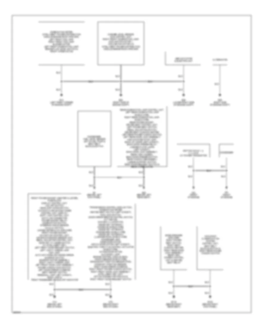
GROUND DISTRIBUTION
Ground Distribution Wiring Diagram for Nissan Murano S 2007
List of elements for Ground Distribution Wiring Diagram for Nissan Murano S 2007:
- Abs actuator & electric unit
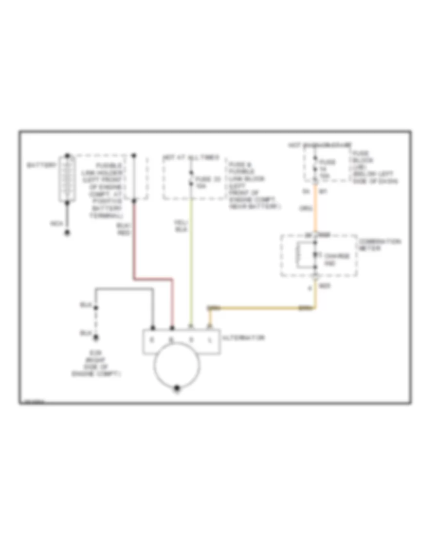
- Alternator
- B105 (behind right kick panel)
- B116 (behind right rear seat)
- B20 (behind left rear seat)
- B7 (behind left kick panel)
- Bose speaker amplifier, right power seat switch, right seat cushion heater, right rear door lock assembly, rear view camera control unit & heated seat relay
- Combination meter, intelligent power distribution module engine room (ipdm e/r), left front fog lamp, right front fog lamp, blower motor, left front combination lamp, brake fluid level switch & front wiper motor
- Condenser
- Condenser, fuel level sensor unit & fuel pump & seat belt buckle switch
- E13 (left front corner of engine compt)
- E26 (lower right side of engine compt)
- E28 (right side of engine compt)
- E29 (right side of engine compt)
- F23 (front of engine)
- F61 (front of engine)
- Front power socket (center cluster), fuse block, display control unit, vdc off switch, headlamp aiming switch, automatic drive positioner control unit, display, shift lock control unit, data link connector, power socket relay, combination switch, steering angle sensor, a/c & av switch, unified meter & a/c amplifier, front power socket, navigation control unit, air bag diagnosis sensor unit, pedal adjusting control unit, door key cylinder switch (w/ intelligent key), left front door request switch, left vanity mirror lamp, map lamp, auto anti-dazzling inside mirror, sunroof switch, sunroof motor assembly, right vanity mirror lamp, left front door lock assembly, power window main switch, left door mirror (w/defog), seat memory switch, personal lamp (left & right), room lamp & front passenger air bag off indicator
- Ignition coils 1, 2, 3, 4, 5 & 6 (w/ power transistor)
- M14 (behind left end of dash)
- M78 (behind right end of dash)
- Occupant classification system control unit, seat belt buckle switch & right rear power window switch
- Rear combination lamp control unit, left rear combination lamp shield wire, right rear combination lamp, shield wire, rear power socket, driver seat control unit, left power seat switch, pedal adjusting switch, driver seat cushion heater, left rear power window switch, left rear door lock assembly, high mounted stop lamp, back up lamps (left & right), back door opener relay, license plate lamps (left & right), back door lock assembly, rear view camera, back door opener switch, rear window defogger(-), lumbar support switch, back door request switch & rear wiper motor
- Transmission control module (tcm), combination meter, heated seat switch (left & right), awd lock switch, door mirror remote control switch, cvt device, coin box illumination, inside key antenna-1 (console) shield wire, inside key antenna-2 (dashboard) shield wire, inside key antenna-3 (luggage room) shield wire, condenser, bcm, mode door motor, air mix door motor (left & right), electric throttle control actuator shield wire, intake door motor, glove box lamp, engine control module (ecm), knock sensor shield wire, crankshaft position sensor (pos), camshaft position sensor, right door mirror (w/defog) right front power window switch, right front door lock assembly, intelligent key unit, option connector for dvd & right front door request switch
- Washer level sensor, awd control unit, right front combination lamp, cooling fan motor 1, cooling fan motor 2 & intelligent power distribution module engine room (ipdm e/r)
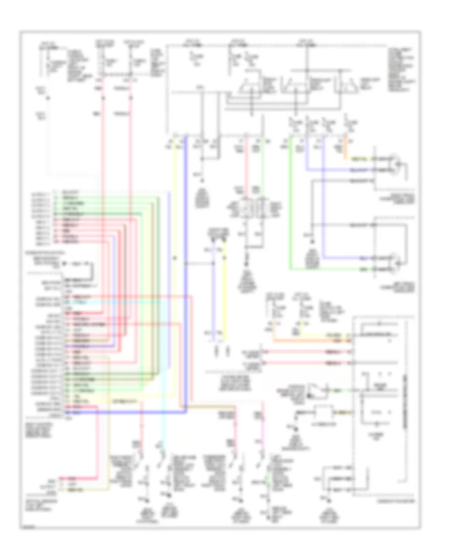
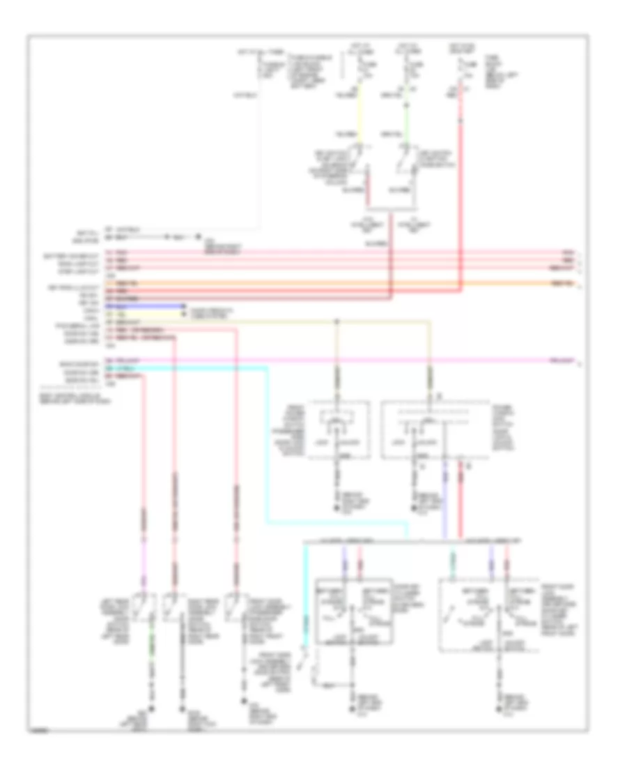
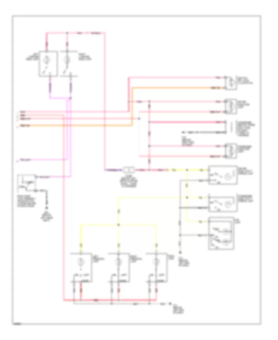
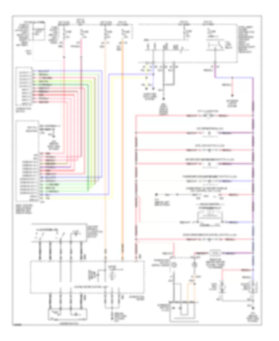
HEADLIGHTS
Headlights Wiring Diagram, with Xenon Lamps for Nissan Murano S 2007
List of elements for Headlights Wiring Diagram, with Xenon Lamps for Nissan Murano S 2007:
- (behind right end of dash) m78
- (below left side of dash)
- (or red)
- 12a m1
- 15a
- 4b m2
- 5a m1
- Acc sw
- Alternator
- Auto lt in
- Auto lt pwr
- B105 (behind right kick panel)
- Bat (f/l)
- Body control module (bcm) (behind left side of dash)
- Brake ind
- Can-h
- Can-l
- Charge ind
- Comb sw in 1
- Combi sw in 2
- Combi sw in 3
- Combi sw in 4
- Combi sw in 5
- Combi sw out 1
- Combi sw out 2
- Combi sw out 3
- Combi sw out 4
- Combi sw out 5
- Combination meter
- Combination switch
- Computer data lines system
- Cpu
- Door sw (as)
- Door sw (dr)
- Door sw (rl)
- Door sw (rr)
- Driver side front door lock assembly (door switch) (rear of left front door)
- E13 (left front corner of engine compt)
- E28 (right side of engine compt)
- E29 (right side of engine compt)
- Front fog lamp relay
- Fuse & fusible link block (left front of engine compt, near battery)
- Fuse 1 10a
- Fuse 10a
- Fuse 15a
- Fuse 6 10a
- Fuse block (j/b)
- Fusible link f 50a
- Gnd
- Gnd (pwr)
- Headlamp high relay
- Headlamp low relay
- Hid cont
- High & low
- High beam ind
- High beam solenoid
- Hot at all times
- Hot in acc or on
- Hot in on or start
- Ign sw
- Input 1
- Input 2
- Input 3
- Input 4
- Input 5
- Intelligent power distribution module engine room (ipdm e/r) (right front of engine compt, behind headlight)
- Left front combination lamp (headlamp)
- Left front fog lamp
- Left rear door lock assembly (door switch) (rear of left rear door)
- M14 (behind left end of dash)
- M34
- M35
- M36
- M78 (behind right end of dash)
- Optical sensor (top left side of dash)
- Output
- Output 1
- Output 2
- Output 3
- Output 4
- Output 5
- Parking brake switch (behind left side of dash)
- Passenger side front door lock assembly (door switch) (rear of right front door)
- Pnk
- Pwr
- Red
- Right front combination lamp (headlamp)
- Right front fog lamp
- Right rear door lock assembly (door switch) (rear of right rear door)
- Rx (comb meter)
- Seat) b20
- Sensor gnd
- Tx (comb meter)
- Unified meter & a/c amplifier (behind lower center of dash)
- Unified meter control unit
Headlights Wiring Diagram, without Xenon Lamps for Nissan Murano S 2007
List of elements for Headlights Wiring Diagram, without Xenon Lamps for Nissan Murano S 2007:
- (behind right end of dash) m78
- (below left side of dash)
- (or red)
- 12a m1
- 15a
- 4b m2
- 5a m1
- Acc sw
- Alternator
- Auto lt in
- Auto lt pwr
- B105 (behind right kick panel)
- Bat (f/l)
- Body control module (bcm) (behind left side of dash)
- Brake ind
- Can-h
- Can-l
- Charge ind
- Comb sw in 1
- Combi sw in 2
- Combi sw in 3
- Combi sw in 4
- Combi sw in 5
- Combi sw out 1
- Combi sw out 2
- Combi sw out 3
- Combi sw out 4
- Combi sw out 5
- Combination meter
- Combination switch
- Computer data lines system
- Cpu
- Door sw (as)
- Door sw (dr)
- Door sw (rl)
- Door sw (rr)
- Driver side front door lock assembly (door switch) (rear of left front door)
- E13 (left front corner of engine compt)
- E28 (right side of engine compt)
- E29 (right side of engine compt)
- Front fog lamp relay
- Fuse & fusible link block (left front of engine compt, near battery)
- Fuse 1 10a
- Fuse 10a
- Fuse 15a
- Fuse 6 10a
- Fuse block (j/b)
- Fusible link f 50a
- Gnd
- Gnd (pwr)
- Headlamp high relay
- Headlamp low relay
- High
- High beam ind
- Hot at all times
- Hot in acc or on
- Hot in on or start
- Ign sw
- Input 1
- Input 2
- Input 3
- Input 4
- Input 5
- Intelligent power distribution module engine room (ipdm e/r) (right front of engine compt, behind headlight)
- Left front combination lamp (headlamp)
- Left front fog lamp
- Left rear door lock assembly (door switch) (rear of left rear door)
- Low
- M14 (behind left end of dash)
- M34
- M35
- M36
- M78 (behind right end of dash)
- Optical sensor (top left side of dash)
- Output
- Output 1
- Output 2
- Output 3
- Output 4
- Output 5
- Parking brake switch (behind left side of dash)
- Passenger side front door lock assembly (door switch) (rear of right front door)
- Pnk
- Pwr
- Red
- Right front combination lamp (headlamp)
- Right front fog lamp
- Right rear door lock assembly (door switch) (rear of right rear door)
- Rx (comb meter)
- Seat) b20
- Sensor gnd
- Tx (comb meter)
- Unified meter & a/c amplifier (behind lower center of dash)
- Unified meter control unit
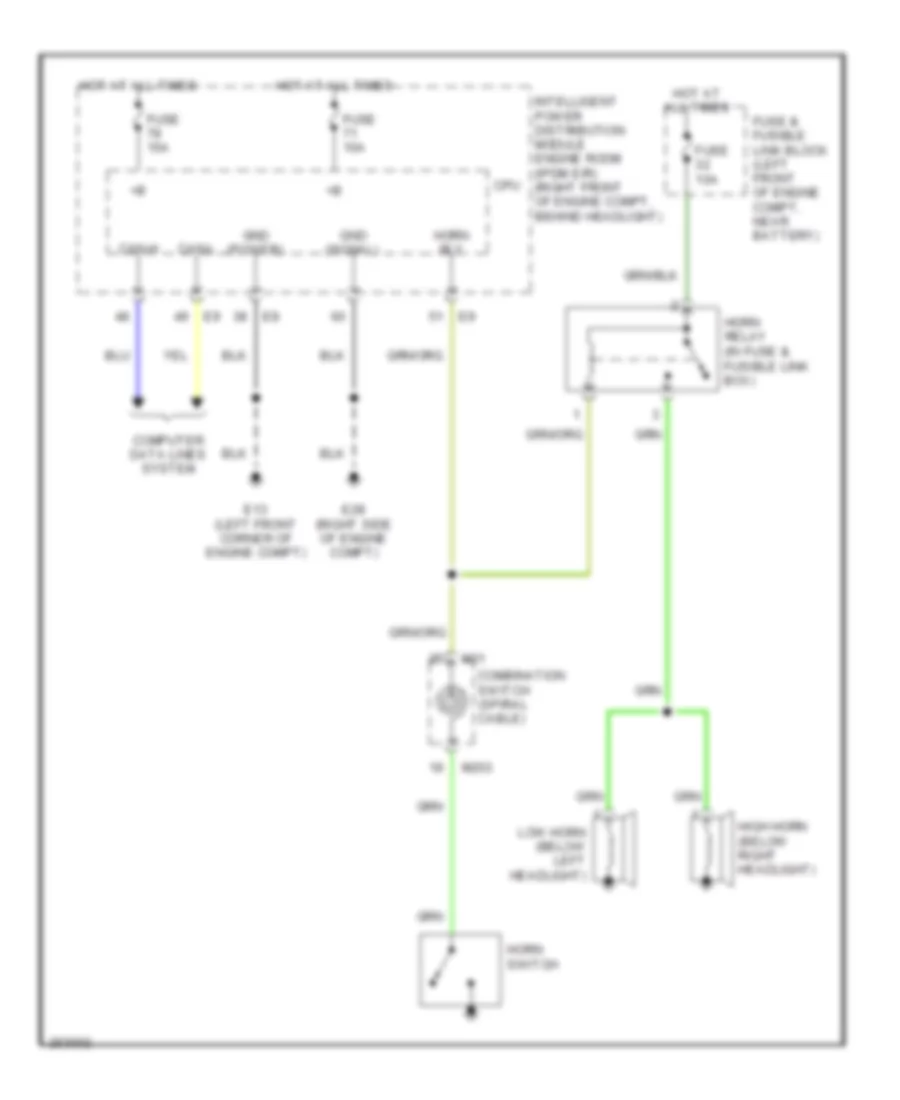
HORN
Horn Wiring Diagram for Nissan Murano S 2007
List of elements for Horn Wiring Diagram for Nissan Murano S 2007:
- (power)
- (signal)
- Can-h
- Can-l
- Combination switch (spiral cable)
- Computer data lines system
- Cpu
- E13 (left front corner of engine compt)
- E28 (right side of engine compt)
- Fuse & fusible link block (left front of engine compt, near battery)
- Fuse 10a
- Fuse 15a
- Gnd
- High horn (below right headlight)
- Horn relay (in fuse & fusible link box)
- Horn rly
- Horn switch
- Hot at all times
- Intelligent power distribution module engine room (ipdm e/r) (right front of engine compt, behind headlight)
- Low horn (below left headlight)
- M203
- M31
INSTRUMENT CLUSTER
Display Wiring Diagram for Nissan Murano S 2007
List of elements for Display Wiring Diagram for Nissan Murano S 2007:
- (left front corner of engine compartment)
- 12a
- 8p/r
- Acc
- Bat
- Can-h
- Can-l
- Compo+
- Compo-
- Computer data lines system
- Cpu
- Dcu dsp
- Display
- Display control unit (behind center of dash)
- Dsp dcu
- Dsp gnd
- Dsp shield
- E13
- Fuse 10a
- Fuse block (j/b) (below left side of dash)
- Gnd
- Gnd (power)
- Gnd (sig)
- Hot at all times
- Hot in acc or on
- Hot in on or start
- Ign
- Intelligent power distribution module engine room (ipdm e/r) (right front of engine compartment, behind headlight)
- Interior lights system
- Inv gnd
- Inv vcc
- M14 (behind left end of dash)
- M42
- M43
- M49
- M50
- Nca
- Pnk
- Rear view camera control unit (if equipped) (right rear of cargo area)
- Red
- Rgb gnd
- Rgb sync
- Sig gnd
- Sig vcc
- Sign gnd
- Sign vcc
- Speed
- Sync gnd
- Tail lamp relay
- Tail/l rly
- Tv+/vtr+
- Tv-/vtr-
- Unified meter & a/c amplifier (behind lower center of dash)
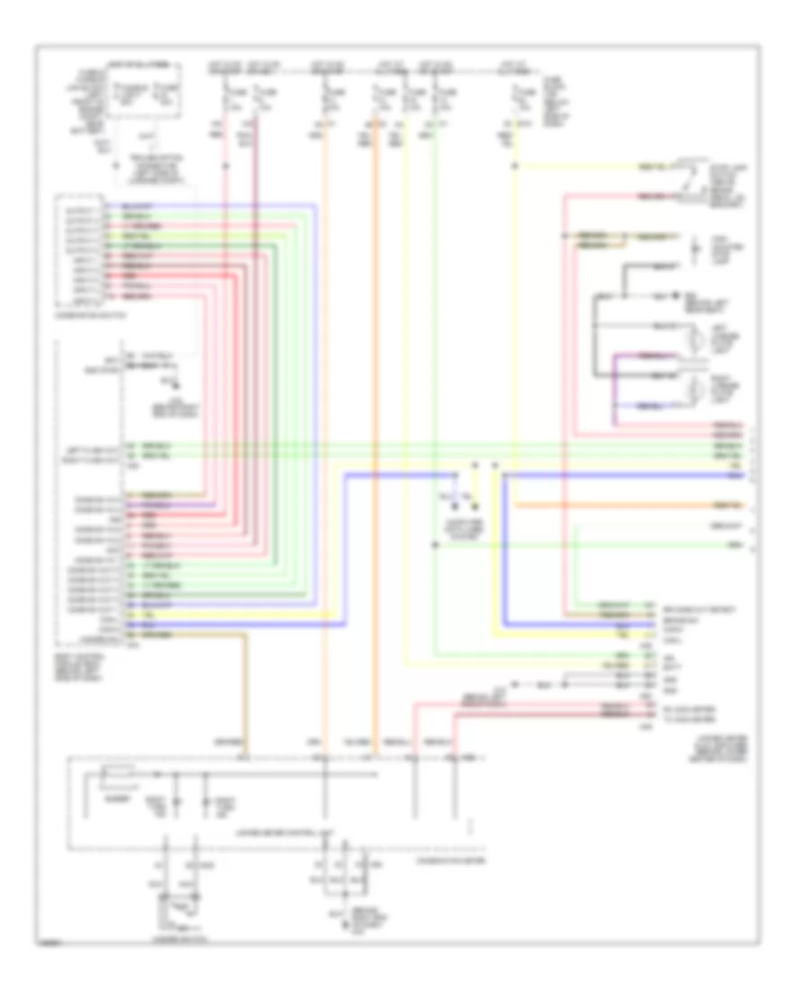
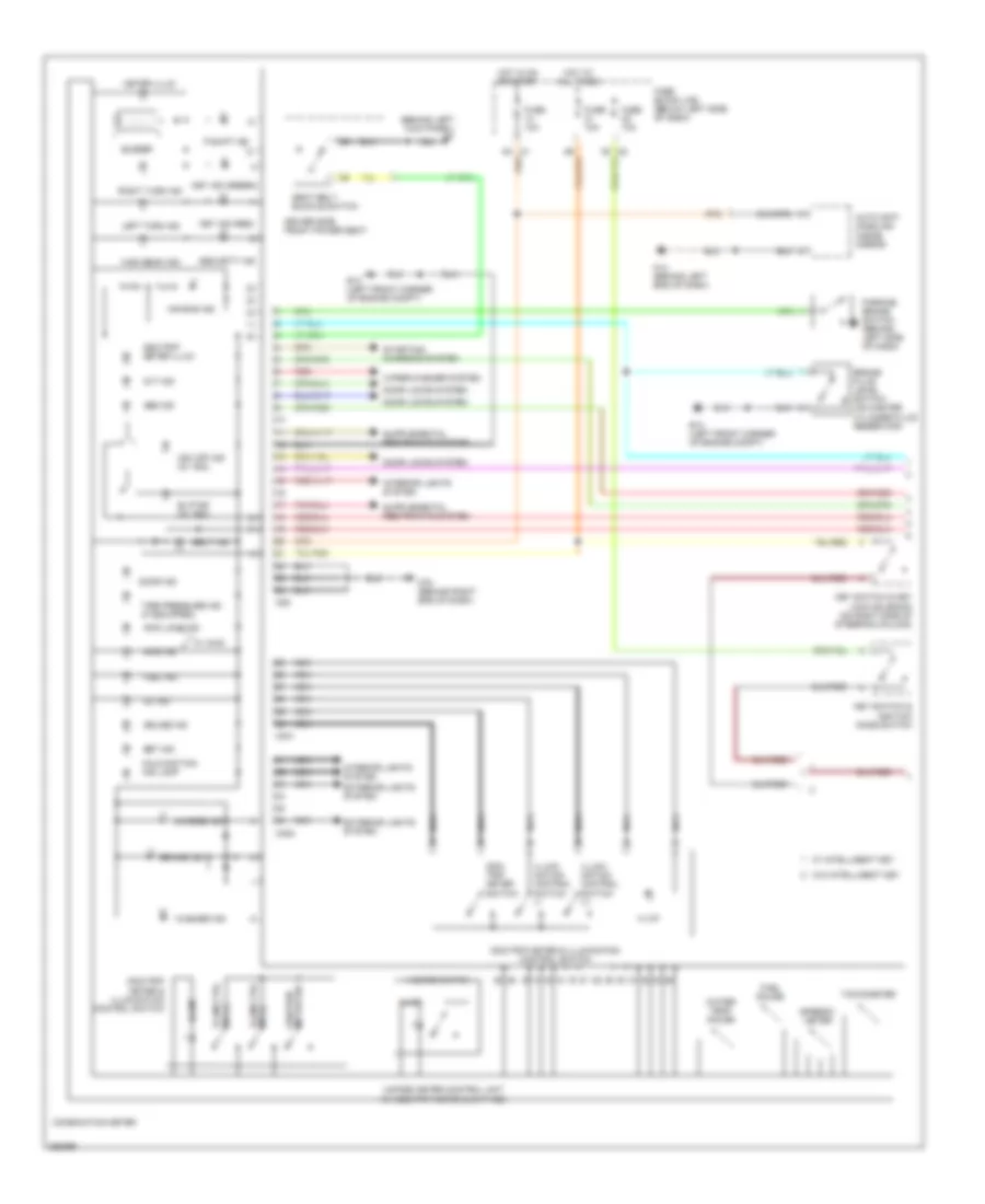
Instrument Cluster Wiring Diagram (1 of 2) for Nissan Murano S 2007
List of elements for Instrument Cluster Wiring Diagram (1 of 2) for Nissan Murano S 2007:
- (behind left kick panel) b7
- Abs ind
- Air bag ind
- Auto anti- dazzling inside mirror
- Awd ind
- Awd lock ind
- Belt ind
- Brake fluid level switch (on master cylinder fluid reservoir)
- Brake ind
- Buzzer
- Charge ind
- Combination meter
- Cruise ind
- Cvt ind
- Door ind
- Door locks system
- Driver side front power seat
- E13 (left front corner of engine compt)
- Exterior lights system
- Fuel gauge
- Fuel ind
- Fuse 10a
- Fuse block (j/b) (below left side of dash)
- Hazard switch
- High beam ind
- Hot at all times
- Hot in on or start
- Illum
- Illum ctrl sw (+)
- Illum ctrl sw (-)
- Illumi- nation control switch (+)
- Illumi- nation control switch (-)
- Interior lights system
- Key ind (green)
- Key ind (red)
- Key switch & ignition knob switch
- Key switch & key lock solenoid (on right side of steering column)
- Left turn ind
- M14 (behind left end of dash)
- M25
- M301
- M302
- M78 (behind right end of dash)
- Malfunction ind lamp
- Meter illum
- Nca
- Odo/ trip meter switch
- Odo/trip meter & illumination control switch
- Odo/trip meter illum
- Odo/trip meter sw
- Oil ind
- P-shift ind
- Parking brake switch (behind left side of dash)
- Red
- Right turn ind
- Seat belt buckle switch
- Security ind
- Set ind
- Slip ind (w/ vdc)
- Speedo- meter
- Starting/ charging system
- Tachometer
- Tire pressure ind (if equipped)
- Unified meter control unit (w/ odo/trip meter & cvt ind)
- Vdc off ind (w/ vdc)
- W/ awd
- W/ intelligent key
- W/o intelligent key
- Washer ind
- Water temp gauge
- Wiper/washer system
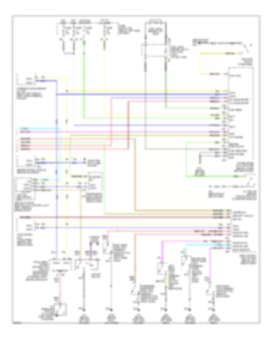
Instrument Cluster Wiring Diagram (2 of 2) for Nissan Murano S 2007
List of elements for Instrument Cluster Wiring Diagram (2 of 2) for Nissan Murano S 2007:
- (behind right end of dash) m78
- (or red)
- 8p/r
- Abs actuator & electric unit (control unit) (right rear of engine compt)
- All times
- At-p range
- Awd control unit (if equipped) (behind left side of dash)
- Awd lock
- Awd lock switch (if equipped)
- B105 (behind right kick panel)
- B17
- B20 (behind left rear seat)
- B401
- Back door lock assembly (door switch) (rear of back door)
- Back door sw
- Batt
- Body control module (bcm) (behind left side of dash)
- Can-h
- Can-l
- Computer data lines system
- Cvt device (second position switch) (in center console)
- Door sw (as)
- Door sw (dr)
- Door sw (rl)
- Door sw (rr)
- Driver side front door lock assembly (door switch) (rear of left front door)
- Engine control module (behind glove box)
- F103
- Fuel level sensor unit & fuel pump (main) (in fuel tank)
- Fuel level sensor unit (sub)
- Fuel sens
- Fuel sens gnd
- Fuse 10a
- Fuse 15a
- Fuse block (j/b) (below left side of dash)
- Gnd
- Gnd (power)
- Hazard sw
- Hot at
- Hot in on
- Hot in on or start
- Ign
- Ign 2
- Ill
- Intelligent power distribution module engine room (right front of engine compt, behind headlight)
- Interior lights system
- Key sw
- Left rear door lock assembly (door switch) (rear of left rear door)
- Lis
- M14 (behind left end of dash)
- M34
- M36
- M49
- M50
- M51
- M78 (behind right end of dash)
- M80
- Nca
- Oil press sw
- Oil pressure switch (on lower right front of engine)
- Passenger side front door lock assembly (door switch) (rear of right front door)
- Right rear door lock assembly (door switch) (rear of right rear door)
- Rx (comb meter)
- Second position sw
- Security ind out
- Starter rly
- Steering angle sensor (w/ vdc) (below left side of dash, near steering column)
- Transmission control module (behind right side of dash)
- Tx (comb meter)
- Unified meter & a/c amplifier (behind lower center of dash)
- Vdc off
- Vdc off switch
- Vdc/tcs/ abs control unit
INTERIOR LIGHTS
Courtesy Lamps Wiring Diagram (1 of 2) for Nissan Murano S 2007
List of elements for Courtesy Lamps Wiring Diagram (1 of 2) for Nissan Murano S 2007:
- (behind left end of dash) m14
- (behind right end of dash) m78
- (door lock & unlock switch)
- (in driver's door)
- (passenger side) (door lock & unlock switch)
- 15a m1
- B105 (behind right kick panel)
- B20 (behind left rear seat)
- Back door sw
- Bat (f/l)
- Battery saver out
- Between full stroke & n
- Body control module (behind left side of dash)
- Can-h
- Can-l
- Computer data lines system
- Cpu
- Door key cylinder switch
- Door sw (as)
- Door sw (dr)
- Door sw (rl)
- Door sw (rr)
- Front door lock assembly (driver side door switch) (rear of left front door)
- Front door lock assembly (driver side) (door key cylinder switch) (rear of left front door)
- Front door lock assembly (passenger side door switch) (rear of right front door)
- Front power window switch
- Full
- Full stroke
- Fuse & fusible link block (left front of engine compt, near battery)
- Fuse 10a
- Fuse block (j/b) (below left side of dash)
- Fusible link f 50a
- Gnd
- Gnd (pwr)
- Hot at all times
- Hot in on or start
- Ign sw
- Key ring illum out
- Key sw
- Key switch & ignition knob switch
- Key switch & key lock solenoid (on right side of steering column)
- Left rear door lock assembly (door switch) (rear of left rear door)
- Lock
- Lock switch
- M2 1b
- M34
- M35
- M36
- M78 (behind right end of dash)
- Pnk
- Power window main switch
- Pwd serial link
- Red
- Right rear door lock assembly (door switch) (rear of right rear door)
- Room lamp out
- Step lamp out
- Unlock
- Unlock switch
- W/ intelligent key
- W/o intelligent key
Courtesy Lamps Wiring Diagram (2 of 2) for Nissan Murano S 2007
List of elements for Courtesy Lamps Wiring Diagram (2 of 2) for Nissan Murano S 2007:
- B20 (behind left rear seat)
- Back door lock assembly (door switch) (lower center of back door)
- Closed
- Condenser (behind upper right side of dash, taped to harness)
- Diode (behind left rear quarter panel, taped to harness)
- Door
- Driver side step lamp
- Driver side vanity mirror lamp
- Ignition key hole illumination
- Left luggage room lamp
- Left personal lamp
- M14 (behind left end of dash)
- M78 (behind right end of dash)
- Map lamp
- Off
- Open
- Passenger side step lamp
- Passenger side vanity mirror lamp
- Pnk
- Red
- Right luggage room lamp
- Right personal lamp
- Room lamp
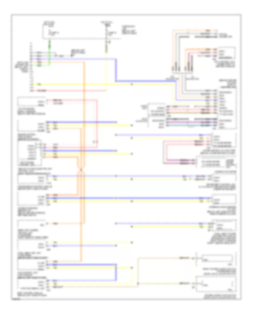
Instrument Illumination Wiring Diagram for Nissan Murano S 2007
List of elements for Instrument Illumination Wiring Diagram for Nissan Murano S 2007:
- (+)
- (-)
- (behind right end of dash) m78
- (sig) gnd
- (under front of center console)
- 12a
- 15a
- A/c & av switch
- Acc
- Awd lock switch (illum)
- Bat (f/l)
- Body control module (bcm) (behind left side of dash)
- Can-h
- Can-hi
- Can-l
- Can-lo
- Coin box (illum)
- Comb sw in 1
- Comb sw in 2
- Comb sw in 3
- Comb sw in 4
- Comb sw in 5
- Comb sw out 1
- Comb sw out 2
- Comb sw out 3
- Comb sw out 4
- Comb sw out 5
- Combination meter
- Combination switch
- Combination switch (spiral cable)
- Computer data lines system
- Console box illum
- Cpu
- Cvt illumination
- Door mirror remote control switch (illum)
- Driver side heated seat switch (illum)
- E28 (right side of engine compt)
- Exterior lights system
- Fuse & fusible link block (left front of engine compt, near battery)
- Fuse 10a
- Fuse 15a
- Fuse block (j/b) (below left side of dash)
- Fusible link f 50a
- Glove box lamp
- Gnd
- Gnd (pwr)
- Hazard switch
- Hot at all times
- Hot in acc or on
- Hot in on or start
- Ign
- Ill
- Ill control
- Ill+
- Illum
- Illum control sw
- Illum meter
- Input 1
- Input 2
- Input 3
- Input 4
- Input 5
- Intelligent power distribution module engine room (ipdm e/r) (right front of engine compt, behind headlight)
- M1 5a
- M14 (behind left end of dash)
- M203
- M25
- M301
- M302
- M31
- M34
- M35
- M62
- M63
- M78 (behind right end of dash)
- Meter illum
- Navi control unit (illum)
- Nca
- Odo/trip
- Odo/trip meter & illumination control switch
- Off
- Output 1
- Output 2
- Output 3
- Output 4
- Output 5
- Passenger side heated seat switch (illum)
- Red
- Resistor (behind center of dash, taped to harness)
- Steering switch (illum)
- Tail lamp relay
- Unified meter control unit
- Vdc off switch (illum)
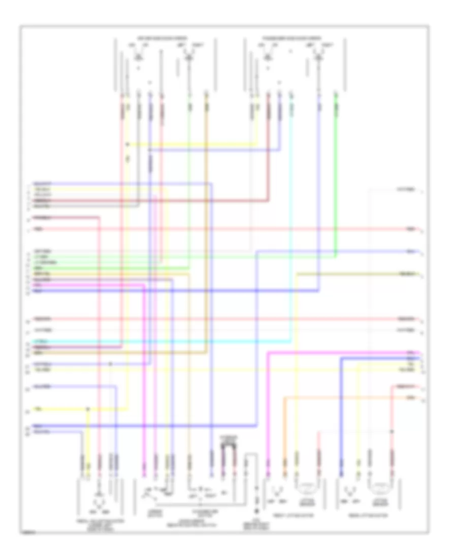
MEMORY SYSTEMS
Memory Systems Wiring Diagram (1 of 3) for Nissan Murano S 2007
List of elements for Memory Systems Wiring Diagram (1 of 3) for Nissan Murano S 2007:
- (behind left end of dash) m14
- (behind left side of dash) (w/ intelligent key) diode
- (behind right end of dash) m78
- (in center console)
- (rear of left front door) driver side front door lock assembly (door switch)
- (w/ intelligent key) key switch & ignition knob switch
- 12a m1
- 15a
- 4b m2
- Acc sw
- Address 1
- Address 2
- Automatic drive positioner control unit (under left side of dash, behind fuse block (j/b))
- Bat (f/l)
- Bat (fuse)
- Bat (ptc)
- Body control module (behind left side of dash)
- Can-h
- Can-l
- Circuit breaker (left side of dash, near fuse block (j/b))
- Computer data lines system
- Cvt device
- Detention switch
- Diode (w/ intelligent key) (behind left side of dash)
- Door sw (dr)
- Fuse & fusible link block (left front of engine compt, near battery)
- Fuse 10a
- Fuse block (j/b) (below left side of dash)
- Fusible link f 50a
- Gnd (power)
- Gnd (sens)
- Gnd (sig)
- Hot at all times
- Hot in acc or on
- Hot in on or start
- Ign sw
- Ignition knob switch
- Ind 1
- Ind 2
- Key sw
- Key switch
- Key switch & key lock solenoid (w/o intelligent key) (on right side of steering column)
- M14 (behind left end of dash)
- M19
- M20
- M34
- M35
- M36
- Memory indicator
- Memory switch-1
- Memory switch-2
- Mirror motor (rh com)
- Mirror mtr (lh com)
- Mirror mtr (lh horiz)
- Mirror mtr (lh vert)
- Mirror mtr (rh horiz)
- Mirror mtr (rh vert)
- Mirror select sw (lh)
- Mirror select sw (rh)
- Mirror sens (lh horiz)
- Mirror sens (lh vert)
- Mirror sens (rh horiz)
- Mirror sens (rh vert)
- Mirror sw (dn)
- Mirror sw (left)
- Mirror sw (right)
- Mirror sw (up)
- Pedal motor (fr)
- Pedal motor (rr)
- Pedal sensor
- Red
- Seat memory switch
- Set sw
- Set switch
- W/ intelligent key
- W/o intelligent key
Memory Systems Wiring Diagram (2 of 3) for Nissan Murano S 2007
List of elements for Memory Systems Wiring Diagram (2 of 3) for Nissan Murano S 2007:
- 31b
- 31c
- Changeover switch
- Door mirror remote control switch
- Driver side door mirror
- Front lifting motor
- Interior lights system
- Left
- Lifting sensor
- M78 (behind right end of dash)
- Mirror switch
- Passenger side door mirror
- Pedal adjusting motor (under left side of dash)
- Rear lifting motor
- Red
- Right
Memory Systems Wiring Diagram (3 of 3) for Nissan Murano S 2007
List of elements for Memory Systems Wiring Diagram (3 of 3) for Nissan Murano S 2007:
- 31a
- 32a
- 33d
- 48c
- 48d
- B20 (behind left rear seat)
- B303
- B304
- Bat (fuse)
- Bat (ptc)
- Can-h
- Can-l
- Computer data lines system
- Condenser
- Driver seat control unit (under driver seat)
- Driver side power seat switch
- Driver side reclining motor
- Driver side sliding motor
- Fr lifting motor (dn)
- Fr lifting motor (up)
- Front lifting sw (dn)
- Front lifting sw (up)
- Fuse 10a
- Fuse block (j/b) (below left side of dash)
- Gnd (power)
- Gnd (sens gnd)
- Gnd (signal)
- Hot in start
- Lifting switch (front)
- Lifting switch (rear)
- Lumbar support motor
- Lumbar support switch
- P range sw
- Pedal adjusting switch
- Pedal sw (ff)
- Pedal sw (rr)
- Pulse sw (fr lifting)
- Pulse sw (reclining)
- Pulse sw (rr lifting)
- Pulse sw (sliding)
- Rear lifting sw (dn)
- Rear lifting sw (up)
- Reclining motor (fr)
- Reclining motor (rr)
- Reclining sensor
- Reclining sw (fr)
- Reclining sw (rr)
- Reclining switch
- Red
- Rr lifting motor (dn)
- Rr lifting motor (up)
- Sliding motor (fr)
- Sliding motor (rr)
- Sliding sensor
- Sliding sw (fr)
- Sliding sw (rr)
- Sliding switch
- Start sw
NAVIGATION
Navigation Wiring Diagram (1 of 2) for Nissan Murano S 2007
List of elements for Navigation Wiring Diagram (1 of 2) for Nissan Murano S 2007:
- (behind right end of dash)
- (behind right rear seat) b116
- 12a
- 8p/r
- Acc
- B20 (behind left rear seat)
- Back-up lamp relay (under left side of dash,
- Bat
- Block (j/b))
- Bus shield
- Bus+
- Bus-
- Camera +
- Camera -
- Camera 6v
- Camera on
- Camera+
- Camera-
- Can-h
- Can-l
- Compo +
- Compo -
- Computer data lines system
- Control 1
- Data link connector (below left side of dash)
- Ddl
- F103
- Fuse & fusible link block (left front of engine compt,
- Fuse 10a
- Fuse 15a
- Fuse block (j/b) (below left side of dash)
- Gnd
- Gnd (pwr)
- Gps ant
- Gps antenna
- Hot at all times
- Hot in on or acc
- Hot in on or start
- Ign
- Ill
- Interior lights system
- M351
- M49
- M50
- M62
- M63
- M78
- M78 (behind right end of dash)
- Navi control unit (under front of center console)
- Nca
- Near battery)
- Near fuse
- Rear view camera (in back door)
- Rear view camera control unit (right rear of cargo area)
- Red
- Rev
- Rev lamp rly transmission control module (tcm) (behind right side of dash)
- Rgb shield
- Rgb sync
- Shield
- Speed
- Sync shield
- Unified meter & a/c amplifier (behind lower center of dash)
- Voice guid +
- Voice guid -
Navigation Wiring Diagram (2 of 2) for Nissan Murano S 2007
List of elements for Navigation Wiring Diagram (2 of 2) for Nissan Murano S 2007:
- A/c & av switch
- Acc
- Audio unit
- Bus shield
- Bus+
- Bus-
- Can-h
- Can-l
- Combination switch (spiral cable)
- Computer data lines system
- Dcu-dsp
- Defogger system
- Display
- Display control unit (behind center of dash)
- Down
- Dsp gnd
- Dsp shield
- Dsp-dcu
- Gnd
- Ign
- Ill
- Ill cont
- Ill+
- Interior lights system
- Inv gnd
- Inv vcc
- M203
- M42
- M43
- M44
- M46
- M78 (behind right end
- M78 (behind right end of dash)
- Mode switch
- Nca
- Of dash)
- Off
- Pnk
- Power switch
- Red
- Rgb gnd
- Rgb shield
- Rgb sync
- Rr def on
- Rv cam
- Rx (aud-dcu)
- Rx (dcu-aud)
- Seek switch
- Shield
- Sig gnd
- Sig vcc
- Sign gnd
- Sign vcc
- Speed
- Steering switch
- Strg sw a
- Strg sw b
- Strg sw c
- Sync gnd
- Sync shield
- Tv+/vtr+
- Tv-/vtr-
- Tx (aud-dcu)
- Tx (dcu-aud)
- Voice guid +
- Voice guid -
- Volume switch
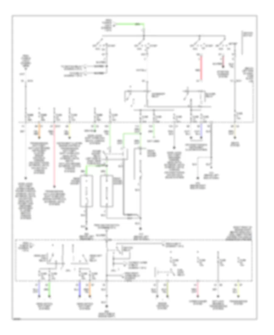
POWER DISTRIBUTION
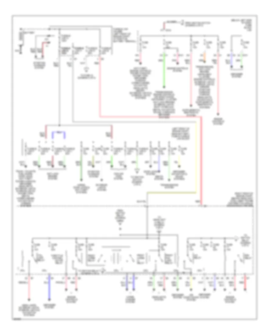
Power Distribution Wiring Diagram (1 of 2) for Nissan Murano S 2007
List of elements for Power Distribution Wiring Diagram (1 of 2) for Nissan Murano S 2007:
- (below left side of dash) fuse block (j/b)
- (left front of engine compt, near battery) fuse & fusible link block
- (right front of engine compt, behind headlight) intelligent power distribution module engine room (ipdm e/r)
- 15a
- 1c e101
- 2a m1
- 2c e101
- 5b m2
- 9a m1
- A/c relay
- Air conditioning system
- Anti-lock brakes system
- Anti-theft, engine controls, power windows, power tops, defogger, warning, wiper/washer, navigation, headlights, memory, exterior lights & interior lights systems
- Battery
- Cooling fans system
- Cpu
- Defogger system
- Defogger, navigation & sound systems
- Door locks system
- E104
- Ecm relay
- Engine controls system
- Exterior lights system
- F37
- From ignition relay (diagram 2 of 2)
- From ignition switch (diagram 2 of 2)
- Front fog lamp relay
- Front wiper hi relay
- Front wiper relay
- Fuse 10a
- Fuse 15a
- Fuse 20a
- Fuse 30a
- Fusible fusible link c 80a
- Fusible fusible link e link b 100a 100a
- Fusible link a 120a
- Fusible link d 60a
- Fusible link e 80a
- Fusible link f 50a
- Fusible link g 30a
- Fusible link h 30a
- Fusible link holder (left front of engine compt, at positive battery terminal)
- Fusible link j 50a
- Fusible link k 40a
- Fusible link l 40a
- Fusible link m 40a
- Head lamps, exterior lights, interior lights & navigation systems
- Headlights system
- Horns, door locks & anti-theft systems
- Nca
- Pnk
- Red
- Seats system
- Starting/ charging system
- Tail lamp relay
- Throttle control motor relay
- To fuse 18 (diagram 2 of 2)
- To headlight hi relay (diagram 2 of 2)
- To ignition relay (diagram 2 of 2)
- To ignition switch (diagram 2 of 2)
- Transmissions system
- Transmissions, engine controls, air conditioning, instrument cluster, anti-lock brakes, exterior lights, shift interlock, seats, navigation, sound, warning & defogger systems
- Trunk, tailgate, fuel doors, door locks, anti-theft, power windows, defogger, headlights, exterior lights, interior lights, power tops, seats, wiper/washer, navigation & warning systems
- Wiper/ washer system
Power Distribution Wiring Diagram (2 of 2) for Nissan Murano S 2007
List of elements for Power Distribution Wiring Diagram (2 of 2) for Nissan Murano S 2007:
- (below left side of dash) fuse block (j/b)
- (not used)
- (right front of engine compt, behind headlight) intelligent power distribution module engine room (ipdm e/r)
- 10a
- 11a
- 12a
- 16a
- 8a 8a m1
- 8c e101
- Acc
- Acc on
- Accessory relay
- Air conditioning & instrument cluster systems
- Anti-lock brakes & transmissions systems
- B20 (behind left rear seat)
- Blower relay
- Cpu
- Door locks, anti-theft, defogger, mirrors, headlights, exterior lights, interior lights, warning, air conditioning, navigation & sound systems
- Door locks, anti-theft, wiper/washer, power windows, interior lights, exterior lights, navigation, headlights, power tops, defogger, instrument cluster, seats & warning systems
- Door locks, shift interlock, seats, warning systems
- E101
- E103
- E28 (right side of engine compt)
- Engine controls system
- From front wiper relay (diagram 1 of 2)
- From fuse 77 (diagram 1 of 2)
- From fuse 88 c (diagram 1 of 2)
- From fusible link d (diagram 1 of 2)
- From fusible link m b (diagram 1 of 2)
- From ignition switch (diagram 2 of 2)
- Front power socket
- Fuel pump relay
- Fuse 10a
- Fuse 15a
- Fuse fuse 10a 10a
- Headlight high relay
- Headlight low relay
- Headlights & anti-theft systems
- Ig1
- Ig2
- Ignition relay
- Ignition switch
- Instrument cluster, engine controls, transmissions, anti-theft, shift interlock, headlights, interior lights, seats, anti-lock brakes, exterior lights & warning systems
- M14 (behind left end of dash)
- M2 1b
- M78 (behind right end of dash)
- Off
- Power socket relay (left side of dash, near fuse block (j/b))
- Rear power socket
- Red
- Seats system
- Start
- Starting/ charging system
- To front wiper hi relay (diagram 1 of 2)
- To fuse 12 (diagram 1 of 2)
- To ignition relay (diagram 2 of 2)
- Transmissions system
- Transmissions, anti-lock brakes, shift interlock, engine controls & exterior lights systems
- Transmissions, anti-theft, anti-lock brakes, instrument cluster, engine controls, mirrors, air conditioning, exterior lights, navigation & warning systems
- Wiper/washer system
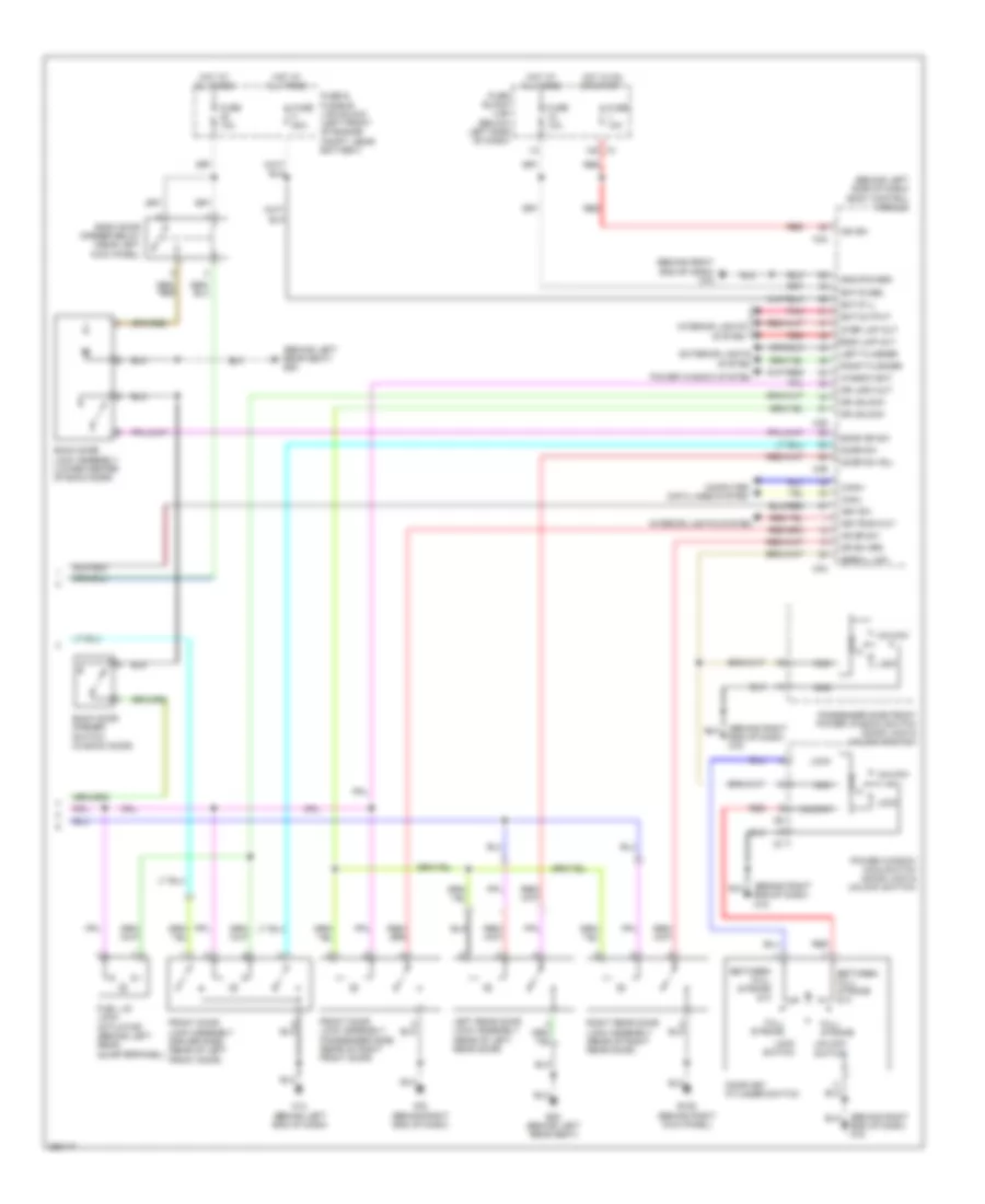
POWER DOOR LOCKS
Power Door Locks Wiring Diagram, with Intelligent Key Unit (1 of 3) for Nissan Murano S 2007
List of elements for Power Door Locks Wiring Diagram, with Intelligent Key Unit (1 of 3) for Nissan Murano S 2007:
- (behind lower center of dash) unified meter & a/c amp
- (behind right end of dash) m78
- (near steering column) steering lock unit
- 5v output
- Acc sw
- Ant +
- Ant -
- Ant1 +
- Ant1 -
- Ant2 +
- Ant2 -
- As switch
- Back dr out
- Back dr sw
- Bat
- Buzzer
- Can-h
- Can-l
- Combination meter
- Computer data lines system
- Dr ant +
- Dr ant -
- Dr ant+
- Dr lock sw
- Earth
- Front door request switch (driver side) (in driver's door)
- Front door request switch (passenger side) (in right front door)
- Fuse 10a
- Fuse block (j/b) (below left side of dash)
- Gnd
- Gnd (pwr)
- Hot at all times
- Hot in acc or on
- Hot in on or start
- Ign
- Ign sw
- Intelligent key unit (behind right side of dash)
- Key ind (green)
- Key ind (red)
- Key ind(red)
- Key sw
- Key switch & ignition knob switch
- M1 12a
- M14 (behind left end of dash)
- M25
- M49
- M50
- M78 (behind right end of dash)
- Nob ind
- Output
- Output inside
- P range sw
- P-shift ind
- Passenger side select unlock relay (behind left side of dash)
- Pnk
- Push sw
- Request sw
- Rr ant +
- Rr ant -
- Signal
- Stop lamp sw
- Strg gnd
- Strg lock sig
- Unified meter control unit
- Unlock out
Power Door Locks Wiring Diagram, with Intelligent Key Unit (2 of 3) for Nissan Murano S 2007
List of elements for Power Door Locks Wiring Diagram, with Intelligent Key Unit (2 of 3) for Nissan Murano S 2007:
- B20 (behind left rear seat)
- Back door request switch (in back door)
- Can- h
- Can- l
- Computer data lines system
- Cpu
- Cvt device (detention switch) (shift)
- Door mirror (driver side) (outside key antenna)
- Door mirror (passenger side) (outside key antenna)
- E101
- E13 (left front corner of engine compartment)
- Fuse 10a
- Fuse 15a
- Fuse block (j/b) (below left side of dash)
- Gnd (power)
- Gnd (signal)
- H/lp hi
- H/lp lo
- Head- lights system
- Horn rly
- Horns system
- Hot at all times
- Inside key antenna-1 (console) (in center console)
- Inside key antenna-2 (dashboard) (behind center of dash)
- Inside key antenna-3 (luggage room) (in cargo area)
- Intelligent key warning buzzer (engine room) (front of engine compartment)
- Intelligent key warning buzzer (inside) (behind left
- Ipdm e/r (intelligent power distribution module engine room) (right front of engine compt, behind headlight)
- Left rear door outside key antenna (in left rear door)
- M78 (behind right end of dash)
- Nca
- Outside key antenna (rear bumper) (in rear bumper)
- Pnk
- Right rear door outside key antenna (in right rear door)
- Side of dash)
- Stop lamp switch (above brake pedal, on bracket)
Power Door Locks Wiring Diagram, with Intelligent Key Unit (3 of 3) for Nissan Murano S 2007
List of elements for Power Door Locks Wiring Diagram, with Intelligent Key Unit (3 of 3) for Nissan Murano S 2007:
- (behind left rear seat) b20
- (behind left side of dash) body control module
- (behind right end of dash) m78
- As dr sw
- B105 (behind right kick panel)
- B20 (behind left rear seat)
- Back door lock assembly (lower center of back door)
- Back door opener relay (near left kick panel)
- Back door opener switch (in back door)
- Back dr sw
- Bat (f/l)
- Bat (fuse)
- Bat output
- Between full stroke & n
- Can-h
- Can-l
- Com
- Computer data lines system
- Cpu
- Door key cylinder switch
- Door sw
- Door sw (rl)
- Dr lock out
- Dr sw (rr)
- Dr unlock
- Exterior lights system
- Front door lock assembly (driver side) (rear of left front door)
- Front door lock assembly (passenger side) (rear of right front door)
- Fuel lid lock actuator (behind left rear quarterpanel)
- Full stroke
- Fuse & fusible link block (left front of engine compt, near battery)
- Fuse 10a
- Fuse block (j/b) (below left side of dash)
- Fuse f 50a
- Gnd
- Gnd (power)
- Hot at all times
- Hot in on or start
- Ign sw
- Interior lights system
- Key ring out
- Key sw
- Left flasher
- Left rear door lock assembly (rear of left rear door)
- Lock
- Lock switch
- M1 15a
- M14 (behind left end of dash)
- M34
- M35
- M36
- M78 (behind right end of dash)
- Passenger side front power window switch (door lock & unlock switch)
- Pnk
- Power window main switch (door lock & unlock switch)
- Power window system
- Red
- Right flasher
- Right rear door lock assembly (rear of right rear door)
- Room lmp out
- Serial link
- Step lmp out
- Unlock
- Unlock switch
- Window bat
Power Door Locks Wiring Diagram, without Intelligent Key Unit for Nissan Murano S 2007
List of elements for Power Door Locks Wiring Diagram, without Intelligent Key Unit for Nissan Murano S 2007:
- (behind left rear quarterpanel) fuel lid lock actuator
- (behind right end of dash) m78
- 15a
- B105 (behind right kick panel)
- B20 (behind left rear seat)
- Back door lock assembly (door switch) (lower center of back door)
- Back door sw
- Bat (fuse)
- Bat f/l
- Bat saver output
- Between full stroke & n
- Body control module (behind left side of dash)
- Can- h
- Can- l
- Can-h
- Can-l
- Closed
- Com
- Computer data lines system
- Cpu
- Door key cylinder switch
- Door lock actuator
- Door lock output
- Door sw (as)
- Door sw (rl)
- Door sw (rr)
- Door switch
- Door unlock output
- Driver side front door lock assembly (rear of left front door)
- Driver's door switch
- E13 (left front corner of engine compartment)
- Exterior lights system
- Flasher output (left)
- Flasher output (right)
- Full stroke
- Fuse & fusible link block (left front of engine compt, near battery)
- Fuse 10a
- Fuse 15a
- Fuse block (j/b) (below left side of dash)
- Fusible link f 50a
- Gnd
- Gnd (power)
- Gnd (signal)
- H/lp hi
- H/lp lo
- Head- lights system
- Horn rly
- Horns system
- Hot at all times
- Hot in on or start
- Ign sw
- Interior lights system
- Ipdm e/r (intelligent power distribution module engine room) (right front of engine compt, behind headlight)
- Key ring ill output
- Key sw
- Key switch (on right side of steering column)
- Left rear door lock assembly (rear of left rear door)
- Lock
- Lock switch
- M14 (behind left end of dash)
- M34
- M35
- M36
- Open
- Out
- Passenger side front door lock assembly (rear of right front door)
- Passenger side front power window switch (door lock & unlock switch)
- Pnk
- Power window main switch (door lock & unlock switch)
- Power windows system
- Pwr window serial link
- Red
- Right rear door lock assembly (rear of right rear door)
- Room lamp output
- Unlock
- Unlock switch
POWER MIRRORS
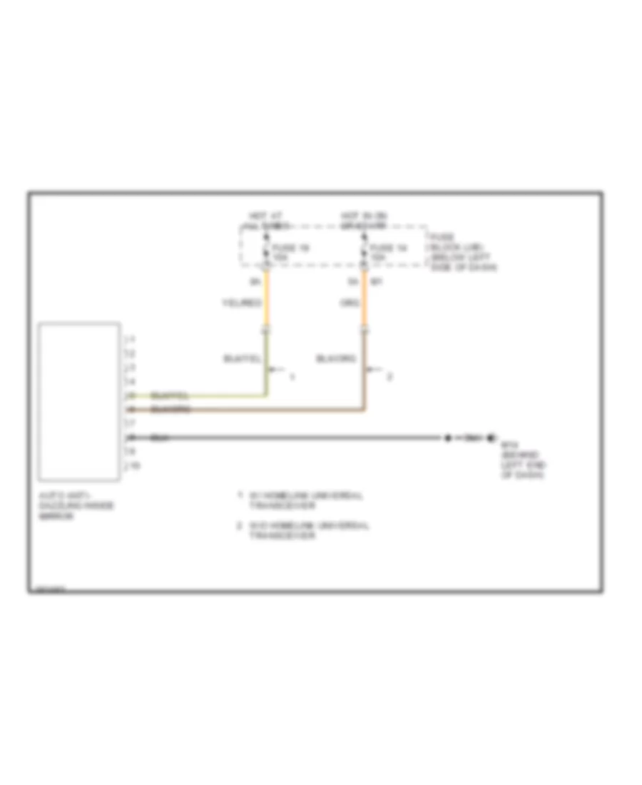
Auto Anti-dazzling Inside Mirror Wiring Diagram for Nissan Murano S 2007
List of elements for Auto Anti-dazzling Inside Mirror Wiring Diagram for Nissan Murano S 2007:
- Auto anti- dazzling inside mirror
- Fuse 14 10a
- Fuse 19 10a
- Fuse block (j/b) (below left side of dash)
- Hot at all times
- Hot in on or start
- M14 (behind left end of dash)
- Transceiver
- W/ homelink universal transceiver
- W/o homelink universal
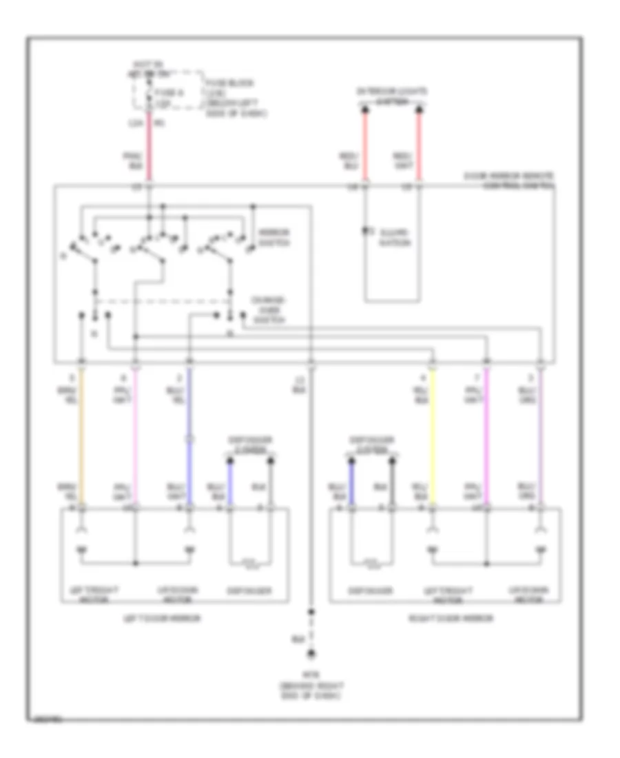
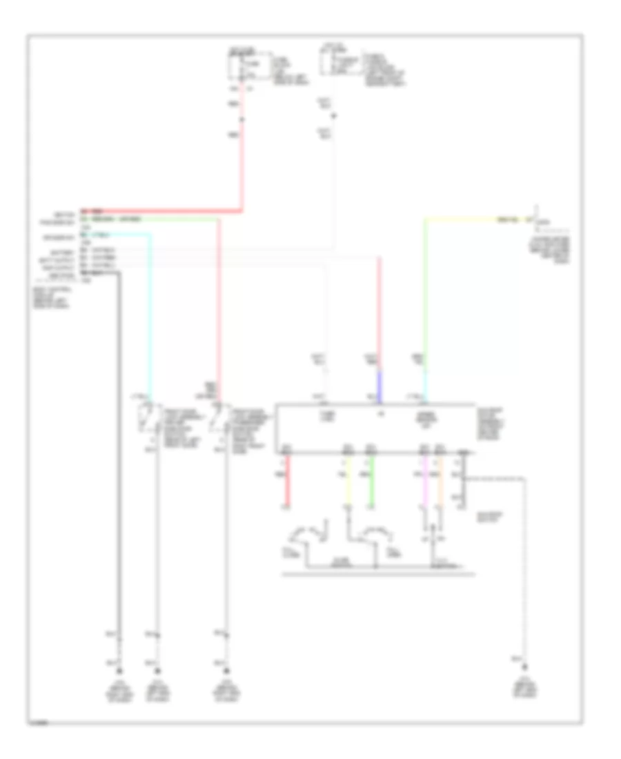
Power Mirrors Wiring Diagram for Nissan Murano S 2007
List of elements for Power Mirrors Wiring Diagram for Nissan Murano S 2007:
- 12a
- Change- over switch
- Defogger
- Defogger system
- Door mirror remote control switch
- Fuse 6 10a
- Fuse block (j/b) (below left side of dash)
- Hot in acc or on
- Illumi- nation
- Interior lights system
- Left door mirror
- Left/right motor
- M78 (behind right end of dash)
- Mirror switch
- Right door mirror
- Up/down motor
POWER SEATS
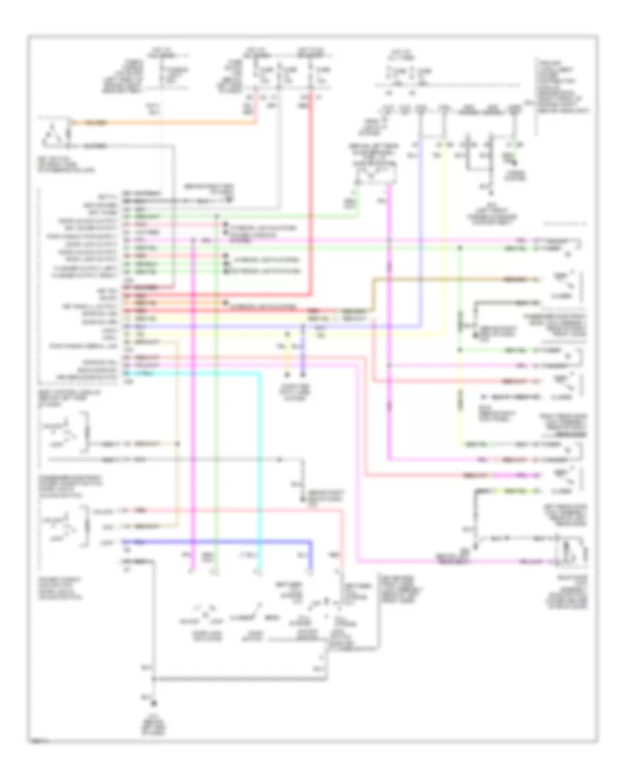
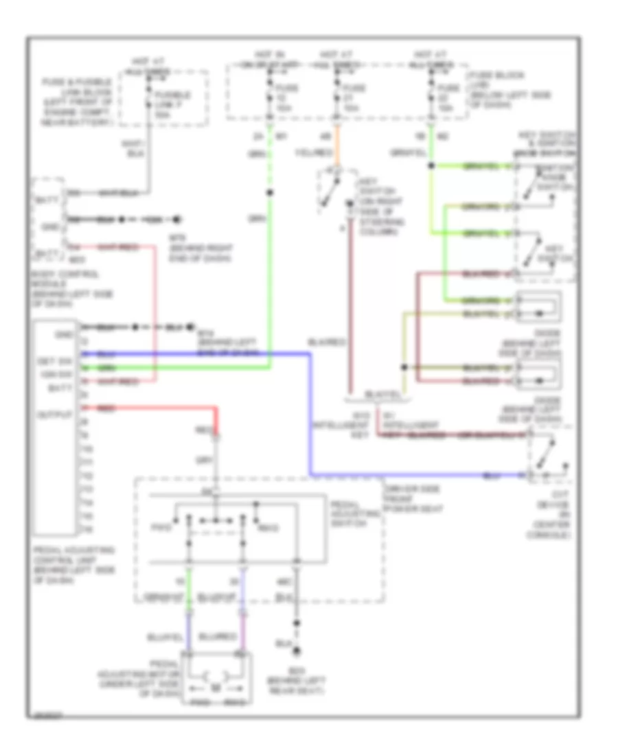
Adjustable Pedal Wiring Diagram for Nissan Murano S 2007
List of elements for Adjustable Pedal Wiring Diagram for Nissan Murano S 2007:
- 48c
- B20 (behind left rear seat)
- Batt
- Body control module (behind left side of dash)
- Cvt device (in center console)
- Det sw
- Diode (behind left side of dash)
- Driver side front power seat
- Fuse & fusible link block (left front of engine compt, near battery)
- Fuse 10a
- Fuse block (j/b) (below left side of dash)
- Fusible link f 50a
- Fwd
- Gnd
- Hot at all times
- Hot in on or start
- Ign sw
- Ignition knob switch
- Key switch
- Key switch & ignition knob switch
- Key switch (on right side of steering column)
- M14 (behind left end of dash)
- M35
- M78 (behind right end of dash)
- Output
- Pedal adjusting control unit (behind left side of dash)
- Pedal adjusting motor (under left side of dash)
- Pedal adjusting switch
- Red
- Rwd
- W/ intelligent key
- W/o intelligent key
Heated Seats Wiring Diagram for Nissan Murano S 2007
List of elements for Heated Seats Wiring Diagram for Nissan Murano S 2007:
- 48b
- 48c
- B105 (behind right kick panel)
- B116 (behind right rear seat)
- B20 (behind left rear seat)
- Driver side front power seat
- Driver side heated seat switch
- Fuse & fusible link block (left front of engine compt, near battery)
- Fuse 12 10a
- Fuse 36 15a
- Fuse block (j/b) (below left side of dash)
- Heated seat relay (right kick panel)
- Heater
- High
- Hot at all times
- Hot in on or start
- Illumination
- Indicator
- Interior lights system
- Low
- M14 (behind left end of dash)
- M78 (behind right end of dash)
- Off
- Passenger side front power seat
- Passenger side heated seat switch
- Seat back heater
- Seat cushion heater
- Thermostat
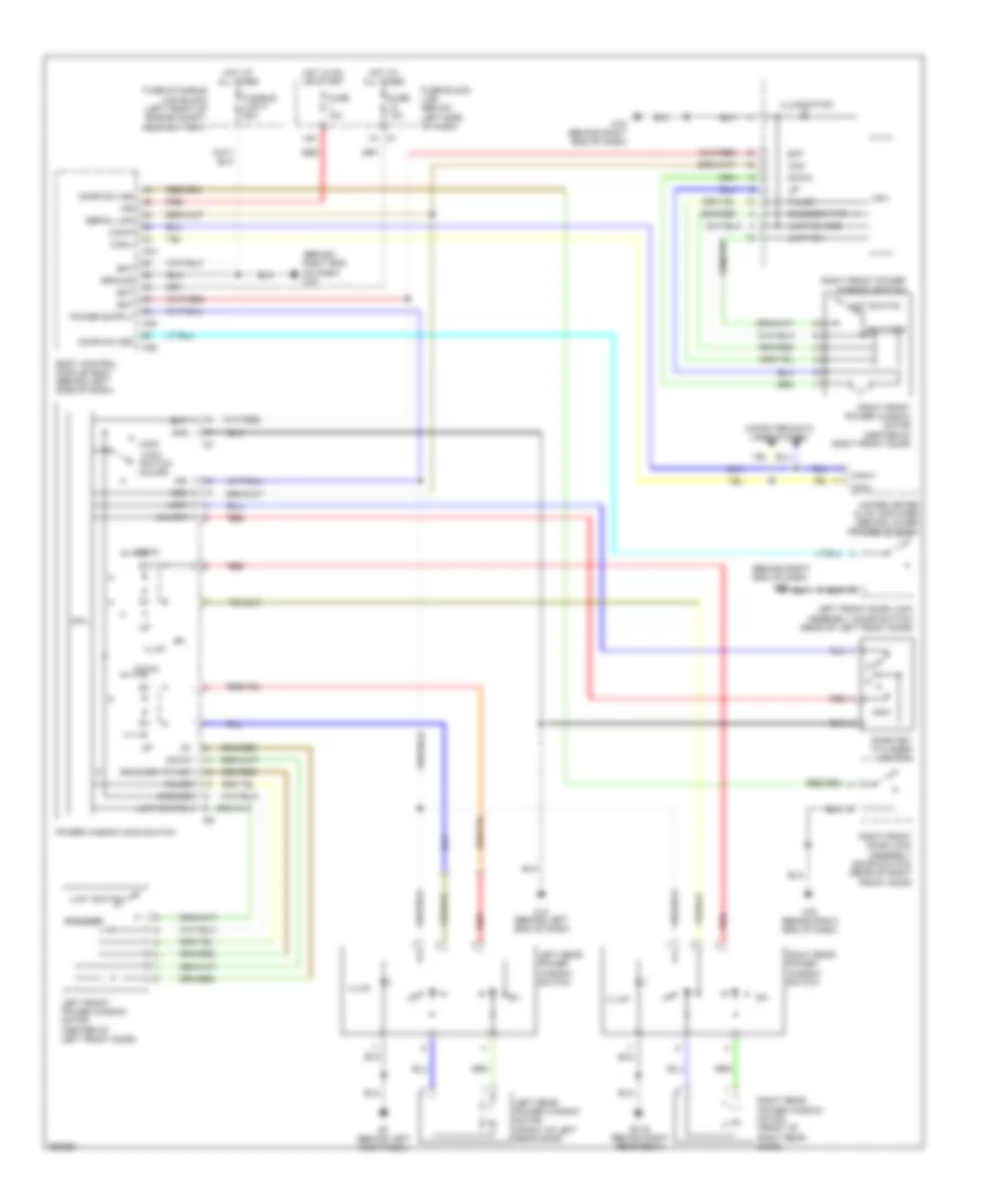
Power Seats Wiring Diagram for Nissan Murano S 2007
List of elements for Power Seats Wiring Diagram for Nissan Murano S 2007:
- 33d
- 48d
- B105 (behind right kick panel)
- B20 (behind left rear seat)
- Back- ward
- Bat (f/l)
- Bat (fuse)
- Body control module (behind left side of dash)
- Bwd
- Condenser
- Down
- Driver side front power seat
- Driver side power seat switch
- Driver side reclining motor
- Driver side sliding motor
- For- ward
- Front lifting motor
- Front lifting switch
- Fuse & fusible link block (left front of engine compt, near battery)
- Fuse 10a
- Fuse block (j/b) (below left side of dash)
- Fusible link f 50a
- Fwd
- Gnd (power)
- Hot at all times
- Lumbar support motor
- Lumbar support switch
- M35
- M78 (behind right end of dash)
- Passenger side front power seat
- Passenger side power seat switch
- Passenger side reclining motor
- Passenger side sliding motor
- Pwr sply (bat)
- Rear lifting motor
- Rear lifting switch
- Reclin- ing switch
- Red
- Sliding switch
POWER TOP/SUNROOF
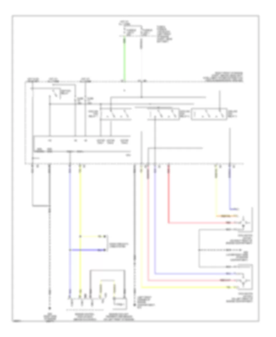
Power Top/Sunroof Wiring Diagram for Nissan Murano S 2007
List of elements for Power Top/Sunroof Wiring Diagram for Nissan Murano S 2007:
- (2p)
- (or red)
- 15a
- 2p/r
- Batt output
- Battery
- Body control module (behind left side of dash)
- Dr door sw
- Front door lock assembly (driver side door switch) (rear of left front door)
- Front door lock assembly (passenger side door switch) (rear of right front door)
- Full close
- Full open
- Fuse & fusible link block (left front of engine compt, near battery)
- Fuse 10a
- Fuse block (j/b) (below left side of dash)
- Fusible link f 50a
- Gnd
- Gnd (pwr)
- Hot at all times
- Hot in on or start
- Ignition
- M14 (behind left end of dash)
- M34
- M35
- M36
- M78 (behind right end of dash)
- Pas door sw
- Rap output
- Red
- Slide switch
- Speed sensor
- Sun roof motor assembly (on front center of roof)
- Sun roof switch
- Sw- bit0
- Sw- bit1
- Sw- bit2
- Sw- bit3
- Sw- bit4
- Tilt switch
- Timer (+ign)
- Unified meter & a/c amplifier (behind lower center of dash)
POWER WINDOWS
Power Windows Wiring Diagram, with Intelligent Key Unit for Nissan Murano S 2007
List of elements for Power Windows Wiring Diagram, with Intelligent Key Unit for Nissan Murano S 2007:
- (behind right end of dash) m78
- 15a
- 1a m1
- B116 (behind right rear seat)
- B7 (behind left kick panel)
- Bat
- Body control module (bcm) (behind left side of dash)
- Can-h
- Can-l
- Com
- Computer data lines system
- Cpu
- Door key cylinder switch
- Door sw (as)
- Door sw (dr)
- Down
- Encoder
- Encoder power
- Encoder pwr
- Fuse & fusible link block (left front of engine compt, near battery)
- Fuse 10a
- Fuse block (j/b) (below left side of dash)
- Fusible link f 50a
- Gnd
- Ground
- Hot at all times
- Hot in on or start
- Ign
- Illum
- Illumination
- Left front door lock assembly (door switch) (rear of left front door)
- Left front power window motor (center of left front door)
- Left rear power window motor (front of left rear door)
- Left rear power window switch
- Limit sw
- Limit sw gnd
- Limit switch
- Lock
- Lock switch unlock
- M14 (behind left end of dash)
- M34
- M35
- M36
- M78 (behind right end of dash)
- Power window main switch
- Pulse
- Red
- Right front door lock assembly (door switch) (rear of right front door)
- Right front power window motor (center of right front door)
- Right front power window switch
- Right rear power window motor (front of right rear door)
- Right rear power window switch
- Serial link
- Unified meter & a/c amplifier (behind lower center of dash)
- Unlk
- Unlock
Power Windows Wiring Diagram, without Intelligent Key Unit for Nissan Murano S 2007
List of elements for Power Windows Wiring Diagram, without Intelligent Key Unit for Nissan Murano S 2007:
- (behind right end of dash) m78
- (behind right rear seat)
- 15a
- 1a m1
- B116
- B7 (behind left kick panel)
- Bat
- Body control module (bcm) (behind left side of dash)
- Can-h
- Can-l
- Closed
- Com
- Computer data lines system
- Cpu
- Door sw (as)
- Door sw (dr)
- Down
- Drivers door lock assembly
- Encoder
- Encoder power
- Encoder pwr
- Fuse & fusible link block (left front of engine compt, near battery)
- Fuse 10a
- Fuse block (j/b) (below left side of dash)
- Fusible link f 50a
- Gnd
- Ground
- Hot at all times
- Hot in on or start
- Ign
- Illum
- Illumination
- Left front power window motor (center of left front door)
- Left rear power window motor (front of left rear door)
- Left rear power window switch
- Limit sw
- Limit sw gnd
- Limit switch
- Lock
- Lock switch unlock
- M14 (behind left end of dash)
- M34
- M35
- M36
- M78 (behind right end of dash)
- Open
- Power window main switch
- Pulse
- Red
- Right front door lock assembly (door switch) (rear of right front door)
- Right front power window motor (center of right front door)
- Right front power window switch
- Right rear power window motor (front of right rear door)
- Right rear power window switch
- Serial link
- Unified meter & a/c amplifier (behind lower center of dash)
- Unlk
- Unlock
RADIO
Radio Wiring Diagram, Bose (1 of 3) for Nissan Murano S 2007
List of elements for Radio Wiring Diagram, Bose (1 of 3) for Nissan Murano S 2007:
- 12a m1
- A/c & av switch
- Acc
- Amp on signal
- Ant sig
- Ant signal
- Audio unit
- B211
- B43
- Back up
- Back-up
- Bus+
- Bus-
- Combination switch (spiral cable)
- Down
- Earth
- Fr sp lh amp +
- Fr sp lh amp -
- Fr sp rh amp +
- Fr sp rh amp -
- Fuse & fusible link block (left front of engine compartment, near battery)
- Fuse 38 15a
- Fuse 6 10a
- Fuse block (j/b) (below left side of dash)
- Gnd
- Hot at all times
- Hot in on or acc
- Ill +
- Ill cont
- Illumination
- Interior lights system
- Lights system interior
- M14 (behind left end of dash)
- M203
- M31
- M44
- M45
- M46
- M78 (behind right end of dash)
- M95
- Mode switch
- Navi earth
- Navi input+
- Navi input-
- Navigation system
- Nca
- Off
- Option connector for dvd
- Pnk
- Power switch
- Red
- Req (sat combi)
- Rod antenna
- Rr sp lh (+) amp
- Rr sp lh (-) amp
- Rr sp rh (+) amp
- Rr sp rh (-) amp
- Rx (combi sat)
- Rx (dcu-aud)
- Rx (sat combi)
- Sat lch (+)
- Sat lch (-)
- Sat rch (+)
- Sat rch (-)
- Satellite radio antenna
- Satellite radio tuner (if equipped) (behind right rear seat)
- Seek switch
- Shield
- Steering switch
- Strg sw a (up)
- Strg sw b (down)
- Strg sw c (gnd)
- Tx (aud-dcu)
- Tx (combi sat)
- Tx (sat combi)
- Volume switch
Radio Wiring Diagram, Bose (2 of 3) for Nissan Murano S 2007
List of elements for Radio Wiring Diagram, Bose (2 of 3) for Nissan Murano S 2007:
- (behind right end of dash) m78
- Acc
- Bus shield
- Bus+
- Bus-
- Can-h
- Can-l
- Computer data lines system
- Dcu dsp
- Display
- Display control unit (behind center of dash)
- Dsp dcu
- Dsp gnd
- Dsp shield
- Fuse 12 10a
- Fuse block (j/b) (below left side of dash)
- Gnd
- Hot in on or start
- Ign
- Inv gnd
- Inv vcc
- M42
- M43
- M78 (behind right end of dash)
- Navigation system
- Nca
- Pnk
- Red
- Rgb gnd
- Rgb sync
- Rx (aud-dcu)
- Shield
- Sig vcc
- Sign gnd
- Sign vcc
- Sync gnd
- Tx (dcu-aud)
Radio Wiring Diagram, Bose (3 of 3) for Nissan Murano S 2007
List of elements for Radio Wiring Diagram, Bose (3 of 3) for Nissan Murano S 2007:
- (behind right kick panel) b105
- B114
- B115
- Bose speaker amplifier (behind right rear seat)
- Control (swb+)
- Fr lh spk1 out+
- Fr lh spk1 out-
- Fr rh spk2 out+
- Fr rh spk2 out-
- Ground
- Input 1+
- Input 1-
- Input 2+
- Input 2-
- Input ch1 fr lh+
- Input ch1 fr lh-
- Input ch2 fr rh+
- Input ch2 fr rh-
- L woofer +
- L woofer -
- Left front door speaker
- Left rear door speaker
- Left tweeter
- R woofer +
- R woofer -
- Red
- Right front door speaker
- Right rear door speaker
- Right tweeter
- Rr lh ch3 input+
- Rr lh ch3 input-
- Rr lh spk3 out+
- Rr lh spk3 out-
- Rr rh ch4 input+
- Rr rh ch4 input-
- Rr rh spk4 out+
- Rr rh spk4 out-
- Woofer
Radio Wiring Diagram, Except Bose (1 of 2) for Nissan Murano S 2007
List of elements for Radio Wiring Diagram, Except Bose (1 of 2) for Nissan Murano S 2007:
- 12a
- A/c & av switch
- Acc
- Ant sig
- Audio unit
- Back up
- Bus+
- Bus-
- Fuse & fusible link block (left front of engine compartment, near battery)
- Fuse 10a
- Fuse 15a
- Fuse block (j/b) (below left side of dash)
- Gnd
- Hot at all times
- Hot in on or acc
- Hot in on or start
- Ill +
- Ill cont
- Interior lights system
- Left front door speaker
- Left rear door speaker
- Left tweeter (6 speakers)
- Lh fr sp (+)
- Lh fr sp (-)
- Lh rr sp (+)
- Lh rr sp (-)
- M14 (behind left end of dash)
- M44
- M45
- M46
- M95
- Navigation system
- Nca
- Option connector for dvd
- Pnk
- Red
- Req (sat combi)
- Rh fr sp (+)
- Rh fr sp (-)
- Rh rr sp (+)
- Rh rr sp (-)
- Right front door speaker
- Right rear door speaker
- Right tweeter (6 speakers)
- Rod antenna
- Rx (dcu aud)
- Rx (sat combi)
- Sat lch (+)
- Sat lch (-)
- Sat rch (+)
- Sat rch (-)
- Shield
- Strg sw a (up)
- Strg sw b (down)
- Strg sw c (gnd)
- Tx (aud dcu)
- Tx (combi sat)
- Voice guid +
- Voice guid -
Radio Wiring Diagram, Except Bose (2 of 2) for Nissan Murano S 2007
List of elements for Radio Wiring Diagram, Except Bose (2 of 2) for Nissan Murano S 2007:
- Acc
- Ant sig
- B211
- B43
- Back-up
- Bus shield
- Bus+
- Bus-
- Can-h
- Can-l
- Combination switch (spiral cable)
- Computer data lines system
- Dcu dsp
- Display
- Display control unit (behind center of dash)
- Down
- Dsp dcu
- Dsp gnd
- Dsp shield
- Gnd
- Ign
- Illu
- Interior lights system
- Inv gnd
- Inv vcc
- M14 (behind left end of dash)
- M203
- M31
- M42
- M43
- Mode switch
- Nca
- Off
- Pnk
- Power switch
- Red
- Req (sat com)
- Rgb gnd
- Rgb syn
- Rgb sync
- Rx (aud dcu)
- Rx (combi sat)
- Sat lch (+)
- Sat lch (-)
- Sat rch (+)
- Sat rch (-)
- Satellite radio antenna
- Satellite radio tuner (if equipped) (behind right rear seat)
- Seek switch
- Shield
- Sig gnd
- Sig vcc
- Sign vcc
- Steering switch
- Syn gnd
- Sync gnd
- Tx (dcu aud)
- Tx (sat com)
- Volume switch
SHIFT INTERLOCK
Shift Interlock Wiring Diagram, with Intelligent Key Unit for Nissan Murano S 2007
List of elements for Shift Interlock Wiring Diagram, with Intelligent Key Unit for Nissan Murano S 2007:
- (behind left end of dash) m14
- Bat (+)
- Brake sw
- Cvt device (in center console)
- Detent sw (key)
- Detent sw (shift)
- Detent switch (key)
- Detent switch (shift)
- Diode (behind left side of dash)
- E101
- Fuse 10a
- Fuse block (j/b) (below left side of dash)
- Gnd
- Hot at all times
- Hot in on or start
- Ign knob switch
- Ign sw
- Key lock sol
- Key lock sol output (lock)
- Key lock sol output (unlock)
- Key switch
- Key switch & ignition knob switch
- P/r
- Shift lock control unit (behind left side of dash)
- Shift lock sol output
- Shift lock solenoid
- Stop lamp switch (above bake pedal, on bracket)
- Unified meter & a/c amplifier (behind lower center of dash)
- Vsp signal
Shift Interlock Wiring Diagram, without Intelligent Key Unit for Nissan Murano S 2007
List of elements for Shift Interlock Wiring Diagram, without Intelligent Key Unit for Nissan Murano S 2007:
- (behind left end of dash) m14
- Bat (+)
- Brake sw
- Cvt device
- Detent sw (key)
- Detent sw (shift)
- Detent switch (key)
- Detent switch (shift)
- E101
- Fuse 10a
- Fuse block (j/b) (below left side of dash)
- Gnd
- Hot at all times
- Hot in on or start
- Ign sw
- Key lock sol
- Key lock sol output (lock)
- Key lock sol output (unlock)
- Key switch & key lock solenoid (on right side of steering column)
- P/r
- Shift lock control unit (behind left side of dash)
- Shift lock sol output
- Shift lock solenoid
- Stop lamp switch (above bake pedal, on bracket)
- Unified meter & a/c amplifier (behind lower center of dash)
- Vsp signal
STARTING/CHARGING
Charging Wiring Diagram for Nissan Murano S 2007
List of elements for Charging Wiring Diagram for Nissan Murano S 2007:
- Alternator
- Battery
- Charge ind
- Combination meter
- E29 (right side of engine compt)
- Fuse & fusible link block (left front of engine compt, near battery)
- Fuse 10a
- Fuse 33 10a
- Fuse block (j/b) (below left side of dash)
- Fusible link holder (left front of engine compt, at positive battery terminal)
- Hot at all times
- Hot in on or start
- M25
- Nca
Starting Wiring Diagram for Nissan Murano S 2007
List of elements for Starting Wiring Diagram for Nissan Murano S 2007:
- Acc
- Battery
- Can- h rly
- Can- l rly
- Computer data lines system
- Cpu
- Cvt unit (bottom left of transmission)
- E13 (left front corner of engine compt)
- E28 (right side of engine compt)
- F103
- F104
- Fuse & fusible link block (left front of of engine compt, near battery)
- Fuse 10a
- Fuse 15a
- Fusible link m 40a
- Hot at all times
- Ignition switch
- Inh sw1
- Inh sw2
- Inh sw3
- Inh sw3 mon
- Inh sw3m
- Inh sw4
- Intelligent power distribution module engine room (ipdm/er) (right front of engine compt, behind headlight)
- Nca
- Off
- Off off off on on
- Off off on on on
- Off on off on off
- Off on on on off
- P r n d l
- Park/ neutral position switch
- Shift position
- Start
- Starter motor
- Starter relay
- Starter rly
- Transmission control module (tcm) (behind right side of dash)
SUPPLEMENTAL RESTRAINTS
Supplemental Restraints Wiring Diagram (1 of 2) for Nissan Murano S 2007
List of elements for Supplemental Restraints Wiring Diagram (1 of 2) for Nissan Murano S 2007:
- (behind left end of dash) m14
- (behind right end of dash) m78
- (partial) (below left side of dash)
- Air bag
- Air bag diagnosis sensor unit (below center console, between seats)
- Air bag w/l
- As1 (+)
- As1 (-)
- As2 (+)
- As2 (-)
- B109
- B11
- Belt
- C-lh (+)
- C-lh (-)
- C-rh (+)
- C-rh (-)
- Can h
- Can l
- Combination meter
- Computer data lines system
- Data link connector
- Dr1 (+)
- Dr1 (-), dr2 -)
- Dr2 (+)
- Eczs (+)
- Eczs (-)
- Front passenger air bag off indicator
- Fuse 10a
- Fuse block (j/b) (behind left side of dash)
- Gnd
- Ground
- Hot in on or start
- Ignition
- K-line
- Left front seat belt pre- tensioner (base of left "b" pillar)
- Left front side air bag module (driver seat)
- Left side air bag (satellite) sensor (beneath left front seat)
- Left side curtain air bag module (rear center of roof)
- Lh buckle sw
- M14 (behind left end of dash)
- M25
- M64
- Nca
- Ods input
- P-lh (+)
- P-lh (-)
- P-rh (+)
- P-rh (-)
- Red
- Rh buckle sw
- Right front seat belt pre- tensioner (base of right "b" pillar)
- Right front side air bag module (front passenger seat)
- Right side air bag (satellite) sensor (beneath right front seat)
- Right side curtain air bag module (rear center of roof)
- S-lh (+)
- S-lh (-)
- S-rh (+)
- S-rh (-)
- Sat lh (+)
- Sat lh (-)
- Sat rh (+)
- Sat rh (-)
- Seat belt reminder
- Telltale cut off
- To warning system
Supplemental Restraints Wiring Diagram (2 of 2) for Nissan Murano S 2007
List of elements for Supplemental Restraints Wiring Diagram (2 of 2) for Nissan Murano S 2007:
- (behind front center of grille, near hood latch) crash zone sensor
- B116 (behind right rear seat)
- B20 (behind left rear seat)
- Belt tension sensor (near right "b" pillar)
- Bts 5v
- Bts gnd
- Bts signal
- Combination switch (spiral cable)
- Commu- nication
- Driver air bag module
- Driver side front power seat
- Fast- ened
- Fastened
- Front passenger air bag module
- Gnd
- Ign
- M201
- M202
- Nca
- Occupant classification system control unit
- Occupant classification system sensor
- Passenger side front power seat
- Ps 5v
- Ps gnd
- Ps signal
- Red
- Seat belt buckle switch
- Un- fastened
TRANSMISSION
A/T Wiring Diagram for Nissan Murano S 2007
List of elements for A/T Wiring Diagram for Nissan Murano S 2007:
- (behind right end of dash)
- 2nd pos
- 2nd pos sw
- Atf temp sens
- Auto
- Auto mod
- Batt
- Brake sw
- Can-h
- Can-l
- Chip select
- Clock
- Combination meter
- Computer data lines system
- Cvt device
- Cvt fluid temp sensor
- Cvt ind
- Cvt unit (bottom left of transmission)
- Data i/o
- Data link connector (below left side of dash)
- Dwn
- Engine control module (behind glove box)
- Exterior lights system
- Fuse 10a
- Fuse block (j/b) (below left side of dash)
- Gnd
- Hot at all times
- Hot in on or start
- Ign
- Inh sw1
- Inh sw2
- Inh sw3
- Inh sw3 mon
- Inh sw4
- Ipdm e/r (intelligent power distribution module engine room) (right front of engine compt, behind headlight)
- Line press sol valve
- Lock- up select sol valve
- Lp sol
- Lu select sol
- M14 (behind left end of dash)
- M78
- M78 (behind right end of dash)
- Man
- Man mode
- Mod sel sw
- Off
- Park/neutral position switch
- Pnk
- Pos sel sw
- Pri pres sens
- Pri spd sens
- Primary pressure sensor
- Primary speed sensor
- Red
- Rev lamp rly
- Rom-assy
- S/m-a
- S/m-b
- S/m-c
- S/m-d
- Sec pres sens
- Sec pres sol
- Sec spd sens
- Secon- dary press sol valve
- Secondary pressure sensor
- Secondary speed sensor (integral to cvt unit)
- Sel1
- Sel2
- Sel3
- Sens
- Sens +5v
- Sens gnd
- Shft dwn
- Shft up
- Starter rly
- Starting system
- Step motor
- Stop lamp switch (above brake pedal, on bracket)
- Tcc sol
- Tcc sol valve
- Transmission control module (tcm) (behind right side of dash)
- Unified meter & a/c amp (behind lower center of dash)
- Unified meter control unit
- Vign
AWD Wiring Diagram for Nissan Murano S 2007
List of elements for AWD Wiring Diagram for Nissan Murano S 2007:
- (behind left end of dash) m14
- Awd
- Awd control unit (behind left side of dash)
- Awd lock
- Awd lock switch
- Awd solenoid valve (under center rear of vehicle, near differential)
- Awdsol+
- Awdsol-
- Batt
- Can-h
- Can-l
- Combination meter
- Computer data lines system
- Data link connector (below
- E28 (right side of engine compt)
- Fuse & fusible link block (left front of engine compt)
- Fuse 10a
- Fuse block (j/b) (below left side of dash)
- Gnd
- Hot at all times
- Hot in on or start
- Ign
- Intelligent power distribution module (ipdm e/r) (right front of engine compt)
- Interior lights system
- K-line
- Left side of dash)
- M78 (behind
- M78 (behind right end of dash)
- Right end of dash)
- Unified meter & a/c amp (behind lower center of dash)
- Unified meter control unit
TRUNK, TAILGATE, FUEL DOOR
Trunk & Fuel Door Release Wiring Diagram, with Intelligent Key Unit for Nissan Murano S 2007
List of elements for Trunk & Fuel Door Release Wiring Diagram, with Intelligent Key Unit for Nissan Murano S 2007:
- (in back
- B20 (behind left rear seat)
- Back door lock assembly (back door opener actuator) (at lower center of back door)
- Back door opener relay (near left kick panel)
- Back door opener switch
- Back door request switch (in back door)
- Back open out
- Back open sw
- Back req sw
- Bat
- Bat (f/l)
- Bat (fuse)
- Body control module (bcm) (behind left side of dash)
- Can-h
- Can-l
- Computer data lines
- Door locks system
- Door)
- Fuse & fusible link block (left front of engine compt, near battery)
- Fuse 10a
- Fuse block (j/b) (below left side of dash)
- Fusible link f 50a
- Gnd
- Gnd (power)
- Hot at all times
- Intelligent key unit (behind right side of dash)
- Lock out (all)
- M34
- M35
- M78 (behind right end of dash)
- System
- Unlock out (dr)
- Unlock out (oth)
Trunk & Fuel Door Release Wiring Diagram, without Intelligent Key Unit for Nissan Murano S 2007
List of elements for Trunk & Fuel Door Release Wiring Diagram, without Intelligent Key Unit for Nissan Murano S 2007:
- (behind right end of dash) m78
- (in back
- B20 (behind left rear seat)
- Back door lock assembly (back door opener actuator) (lower center of back door)
- Back door opener relay (near left kick panel)
- Back door opener switch
- Back open out
- Back open sw
- Bat (f/l)
- Bat (fuse)
- Body control module (bcm) (behind left side of dash)
- Can-h
- Can-l
- Computer data lines
- Door)
- Front door lock assembly passenger side (unlock sensor) (rear of right front door)
- Fuse & fusible link block (left front of engine compt,
- Fuse 10a
- Fuse block (j/b) (below left side of dash)
- Fusible link f 50a
- Gnd (power)
- Hot at all times
- M34
- M35
- M36
- Near battery)
- System
WARNING SYSTEMS
Warning Systems Wiring Diagram for Nissan Murano S 2007
List of elements for Warning Systems Wiring Diagram for Nissan Murano S 2007:
- 15a
- Air bag diagnosis sensor unit (below center console, between seats)
- B7 (behind left kick panel)
- Bat
- Batt
- Belt ind
- Body control module (behind left side of dash)
- Buzzer
- Can-h
- Can-l
- Comb sw in 1
- Comb sw in 2
- Comb sw in 3
- Comb sw in 4
- Comb sw in 5
- Comb sw out 1
- Comb sw out 2
- Comb sw out 3
- Comb sw out 4
- Comb sw out 5
- Combination meter
- Combination switch
- Computer data lines system
- Door ind
- Door sw (dr)
- Driver side front door lock assembly (door switch) (rear of left front door)
- Driver side front power seat
- Fuse & fusible link block (left front of engine compt, near battery)
- Fuse 10a
- Fuse block (j/b) (below left side of dash)
- Fusible link f 50a
- Gnd
- Gnd (power)
- Hot at all times
- Hot in on or start
- Ign
- Input 1
- Input 2
- Input 3
- Input 4
- Input 5
- Key sw
- Key switch & ignition knob switch (w/ intelligent key)
- Key switch (w/o intelligent key) (on right side of steering column)
- M14 (behind left end of dash)
- M34
- M35
- M36
- M49
- M50
- M64
- M78 (behind right end of dash)
- Output 1
- Output 2
- Output 3
- Output 4
- Output 5
- Red
- Rx (comb meter)
- Seat belt buckle switch
- Tx (comb meter)
- Unified meter & a/c amplifier (behind lower center of dash)
- Unified meter control unit
WIPER/WASHER
Front Wiper/Washer Wiring Diagram for Nissan Murano S 2007
List of elements for Front Wiper/Washer Wiring Diagram for Nissan Murano S 2007:
- 15a
- Bat
- Body control module (bcm) (behind left side of dash)
- Combination meter
- Combination switch (lighting switch)
- Cpu
- E13 (at left front corner of engine compartment)
- E28 (at right side of engine compartment)
- E28 (at right side of engine compt)
- Fr+
- Fr-
- Front washer motor (on washer fluid reservoir)
- Front wiper high relay
- Front wiper motor (on left side of firewall)
- Front wiper relay
- Fuse & fusible link box (left front of engine compartment, near battery)
- Fuse 10a
- Fuse 15a
- Fuse 30a
- Fuse block (j/b) (below left side of dash)
- Fusible link f 50a
- Gnd
- High
- Hot at all times
- Hot in on or start
- Ign
- Ignition relay
- Input 1
- Input 2
- Input 3
- Input 4
- Input 5
- Intelligent power distribution module engine room (right front of engine compartment, behind headlight)
- Low
- M14 (behind left end of dash)
- M29
- M34
- M35
- Move
- Output 1
- Output 2
- Output 3
- Output 4
- Output 5
- Red
- Stop
- Washer ind
- Washer level sensor (on washer fluid reservoir)
Rear Wiper/Washer Wiring Diagram for Nissan Murano S 2007
List of elements for Rear Wiper/Washer Wiring Diagram for Nissan Murano S 2007:
- 15a red
- Auto stop
- B20 (behind left rear seat)
- Bat
- Body control module (bcm) (behind left side of dash)
- Combination switch (lighting switch)
- Fuse & fusible link box (left front of engine compt, near battery)
- Fuse 10a
- Fuse block (j/b) (below left side of dash)
- Fusible link f 50a
- Gnd
- Hot at all times
- Hot in on or start
- Ign
- Input 1
- Input 2
- Input 3
- Input 4
- Input 5
- Intelligent power distribution module engine room (right front of engine compt, behind headlight)
- M14 (behind left end of dash)
- M29
- M34
- M35
- M36
- M78 (behind right end of dash)
- Move
- Output
- Output 1
- Output 2
- Output 3
- Output 4
- Output 5
- Rear washer motor (on washer fluid reservoir)
- Rear wiper motor (center of back door)
- Red
- Rr+
- Rr-
- Stop

 Čeština
 Dansk
Dansk Deutsch
 Ελληνικά
 English
 English
 Español
 Suomi
Suomi Français
 Français
 עברית
עברית Hrvatski
 Magyar
 日本語
日本語 한국어
한국어 Nederlands
 Polski
 Português
 Português
 Română
 Русский
 Slovenčina
 Slovenščina
 Svenska
 Türkçe
 中文 (中国)