DEFOGGERS
Defogger Wiring Diagram for Toyota 4Runner SR5 1993
 https://portal-diagnostov.com/license.html
Automotive Electricians Portal FZCO
Automotive Electricians Portal FZCO
https://portal-diagnostov.com/license.html
https://portal-diagnostov.com/license.html
Automotive Electricians Portal FZCO
Automotive Electricians Portal FZCO
List of elements for Defogger Wiring Diagram for Toyota 4Runner SR5 1993:
- (1990-91)
- (1990-91) (1992-94)
- (1992-94)
- Am1 fuse 40a
- Cassette r/b (left side of i/p)
- Defog fuse 20a
- Defogger relay
- Defogger switch
- Diode (left rear corner of vehicle)
- Fuse block (left side of i/p)
- Fuse box (r/b 2) (right side of engine compartment)
- G904 (under left rear pillar)
- Gauge fuse 10a
- Hot at all times
- Hot in on or start
- Integration relay
- J/b 1 (left side of i/p)
- Rear power window limit switch (in center of tailgate)
- Rear window defogger
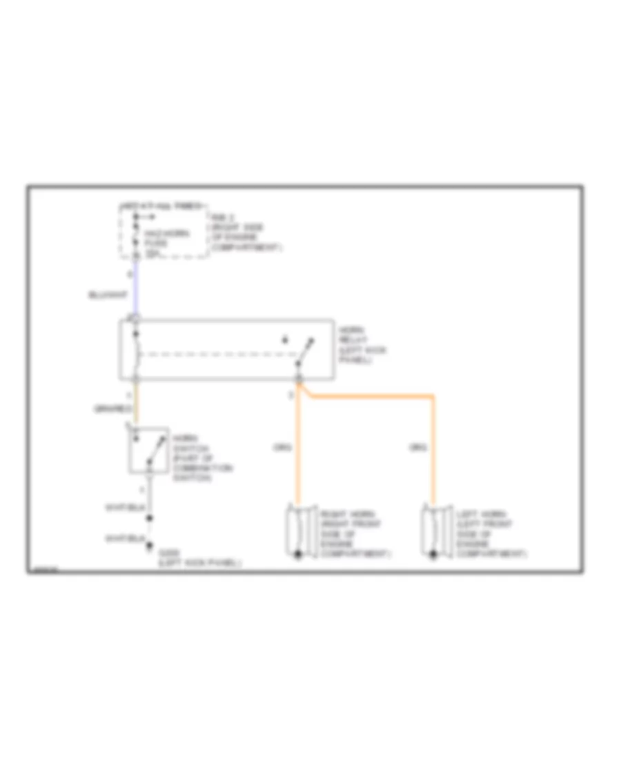
HORN
Horn Wiring Diagram for Toyota 4Runner SR5 1993
List of elements for Horn Wiring Diagram for Toyota 4Runner SR5 1993:
- G200 (left kick panel)
- Haz-horn fuse 15a
- Horn relay (left kick panel)
- Horn switch (part of combination switch)
- Hot at all times
- Left horn (left front side of engine compartment)
- R/b 2 (right side of engine compartment)
- Right horn (right front side of engine compartment)
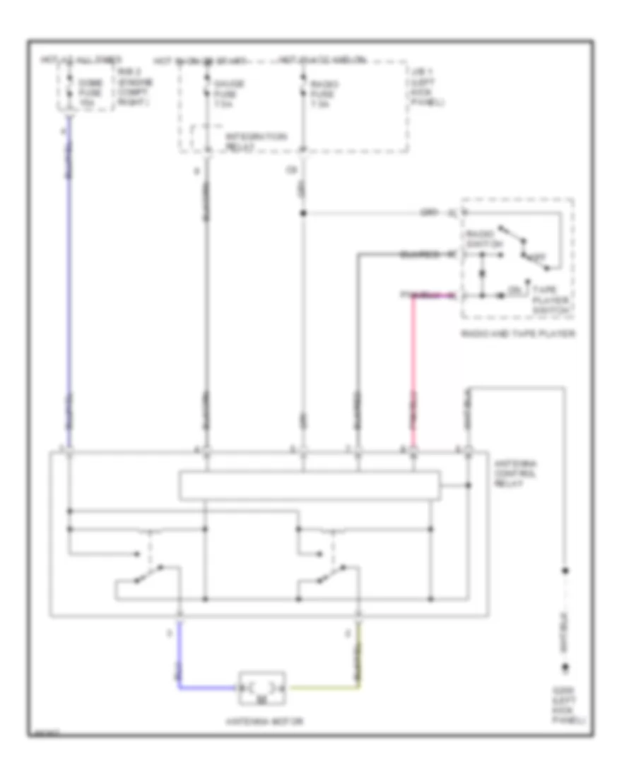
POWER ANTENNA
Power Antenna Wiring Diagram for Toyota 4Runner SR5 1993
List of elements for Power Antenna Wiring Diagram for Toyota 4Runner SR5 1993:
- Antenna control relay
- Antenna motor
- Dome fuse 15a
- G200 (left kick panel)
- Gauge fuse 7.5a
- Hot at all times
- Hot in acc and on
- Hot in on or start
- Integration relay
- J/b 1 (left kick panel)
- Off
- R/b 2 (engine compt. right)
- Radio and tape player
- Radio fuse 7.5a
- Radio switch
- Tape player switch
POWER DOOR LOCKS
Power Door Lock Wiring Diagram for Toyota 4Runner SR5 1993
List of elements for Power Door Lock Wiring Diagram for Toyota 4Runner SR5 1993:
- (2 door)
- (4 door)
- Cassette r/b (left kick panel)
- Dome fuse 15a
- Door control relay (left side of dash)
- G200 (left kick panel)
- Hot at all times
- Left door courtesy switch
- Left door key lock and unlock detection switch
- Left door lock control switch
- Left door lock motor motor and unlock detection switch
- Left rear door lock motor
- Lock
- Power fuse 30a
- R/b 2 (right side of engine compartment)
- Red
- Right door courtesy switch
- Right door key lock and unlock detection switch
- Right door lock control switch
- Right door lock motor motor and unlock detection switch
- Right rear door lock motor
- Unlock
- Unlock warning switch (ignition switch)
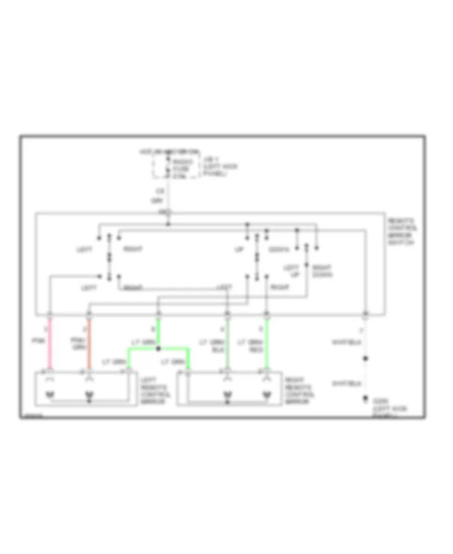
POWER MIRRORS
Power Mirror Wiring Diagram for Toyota 4Runner SR5 1993
List of elements for Power Mirror Wiring Diagram for Toyota 4Runner SR5 1993:
- Down
- G200 (left kick panel)
- Hot in acc or on
- J/b 1 (left kick panel)
- Left
- Left remote control mirror
- Left up
- Pnk
- Radio fuse 7.5a
- Remote control mirror switch
- Right
- Right down
- Right remote control mirror
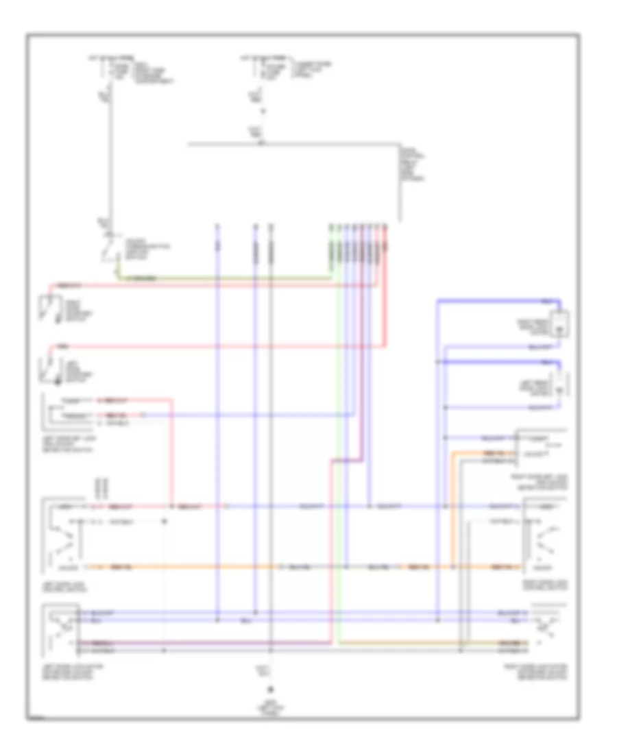
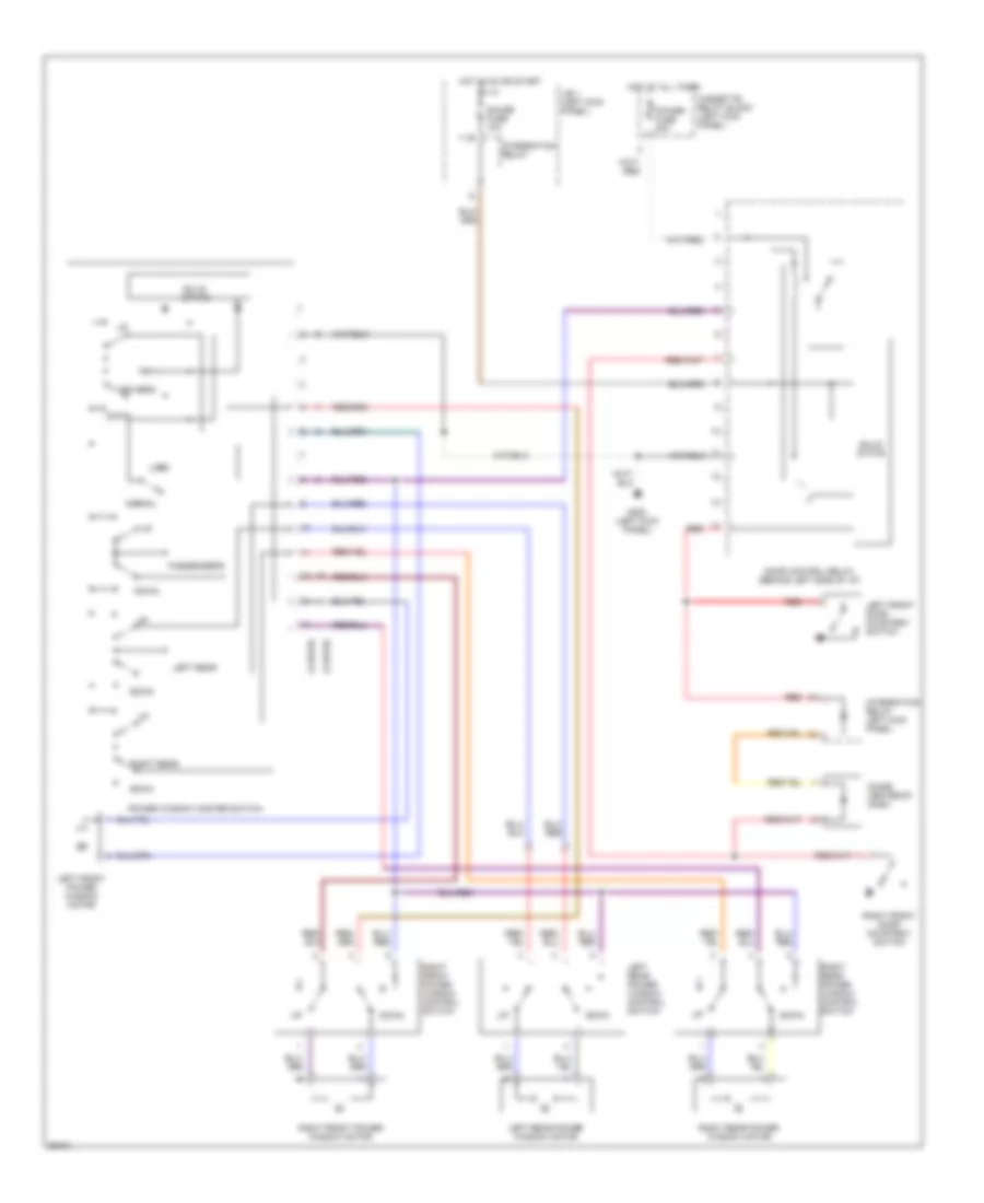
POWER WINDOWS
Front Windows Wiring Diagram for Toyota 4Runner SR5 1993
List of elements for Front Windows Wiring Diagram for Toyota 4Runner SR5 1993:
- (2 door)
- (4 door)
- Cassette relay block (left kick panel)
- Diode center of dash
- Door control relay (behind left side of i/p)
- Down
- Driver's
- G200 (left kick panel)
- Gauge fuse 10a
- Hot at all times
- Hot in on or start
- Integration relay
- Integration relay left kick panel
- J/b 1 (left kick panel)
- Left front door courtesy switch
- Left front power window motor
- Left rear
- Left rear power window control switch
- Left rear power window motor
- Lock
- Normal
- Passenger's
- Power fuse 30a
- Power window master switch
- Red
- Right front door courtesy switch
- Right front power window control switch
- Right front power window motor
- Right rear
- Right rear power window control switch
- Right rear power window motor
- Solid state
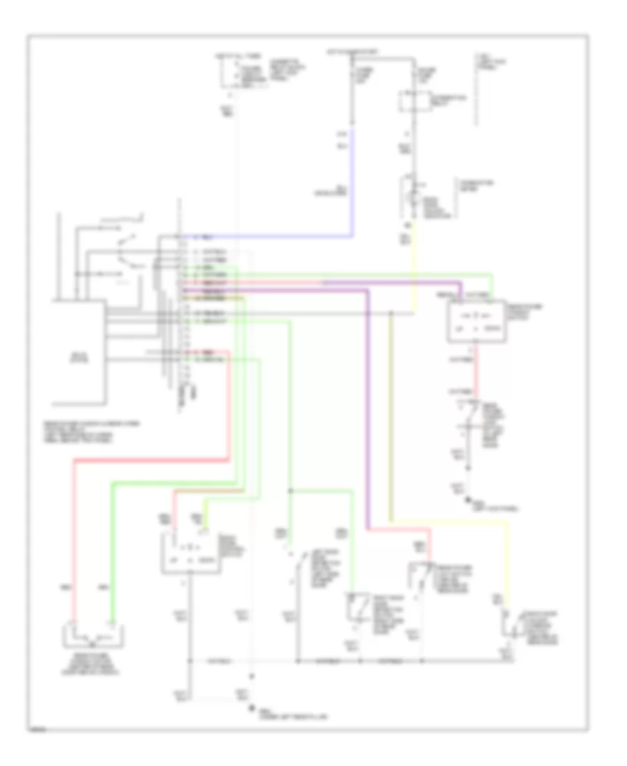
Rear Window Wiring Diagram for Toyota 4Runner SR5 1993
List of elements for Rear Window Wiring Diagram for Toyota 4Runner SR5 1993:
- (1990)
- (1991-93)
- Back door control switch
- Back door unlock warning switch (center of rear door)
- Back door unlock indicator
- C16
- Cassette relay block (left kick panel)
- Combination meter
- Down
- G200 (left kick panel)
- G904 (under left rear pillar)
- Gauge fuse 10a
- Hot at all times
- Hot in on or start
- Integration relay
- J/b 1 (left kick panel)
- Left back door detection switch (left side of rear door)
- Power circuit breaker 30a
- Rear power limit switch (1991-93) (center of rear door)
- Rear power window & rear wiper control relay (left rear side of cargo area, behind trim panel)
- Rear power window lock switch (in left rear door)
- Rear power window motor (center of rear door above window)
- Rear power window switch
- Red
- Right back door detection switch (right side of rear door)
- Solid state
- Wiper fuse 20a
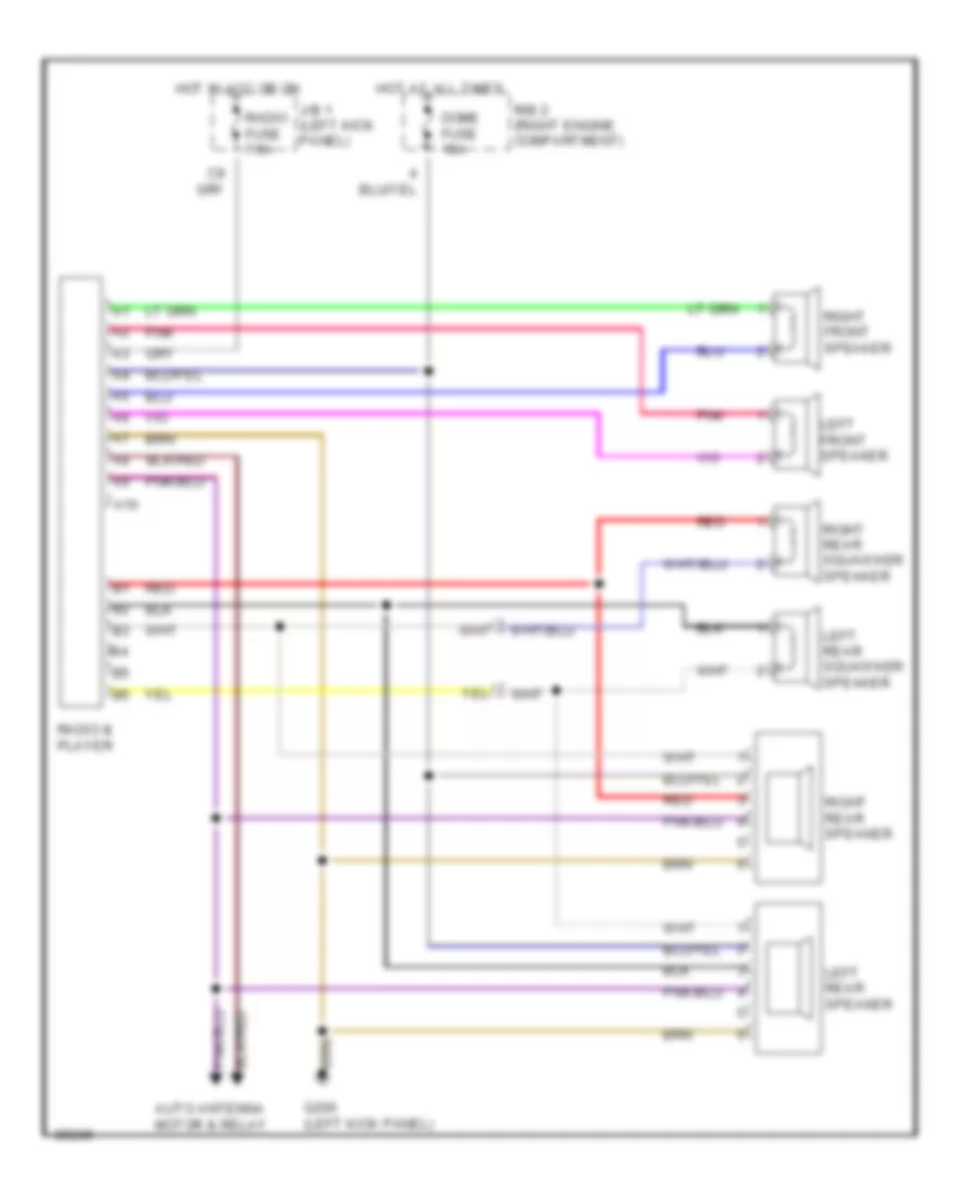
RADIO
Radio Wiring Diagrams for Toyota 4Runner SR5 1993
List of elements for Radio Wiring Diagrams for Toyota 4Runner SR5 1993:
- A10
- Auto antenna motor & relay
- Dome fuse 15a
- G200 (left kick panel)
- Hot at all times
- Hot in acc or on
- J/b 1 (left kick panel)
- Left front speaker
- Left rear speaker
- Left rear squawker speaker
- Pnk
- R/b 2 (right engine compartment)
- Radio & player
- Radio fuse 7.5a
- Red
- Red
- Right front speaker
- Right rear speaker
- Right rear squawker speaker
STARTING/CHARGING
Charging Wiring Diagram for Toyota 4Runner SR5 1993
List of elements for Charging Wiring Diagram for Toyota 4Runner SR5 1993:
- (2.4l a/t) (2.4l m/t, 3.0l)
- Alt fuse 100a 80a
- Am1 fuse 40a
- Battery
- Canadian models
- Charge warning indicator
- Combination meter
- Engine fuse 10a
- Generator
- Headlights system (daytime running light relay)
- Hot in on or start
- Ign fuse 7.5a
- J/b 1 (left kick panel)
- Nca
- R/b 2 (right side of engine compartment)
- Red
Starting Wiring Diagram, A/T for Toyota 4Runner SR5 1993
List of elements for Starting Wiring Diagram, A/T for Toyota 4Runner SR5 1993:
- (2.4l) (3.0l)
- Acc
- Alt fuse 100a 80a
- Am1
- Am1 fuse 40a
- Battery
- Engine controls system
- G200 (left kick panel)
- Ignition switch
- Lock
- Nca
- Park & neutral
- Park/neutral position switch (right side of engine compt 2.4l) (rear of engine compt 3.0l)
- R/b 2 (right side of engine compartment)
- St1
- Start
- Starter
- Starter relay (in r/b 2, right side of engine compartment)
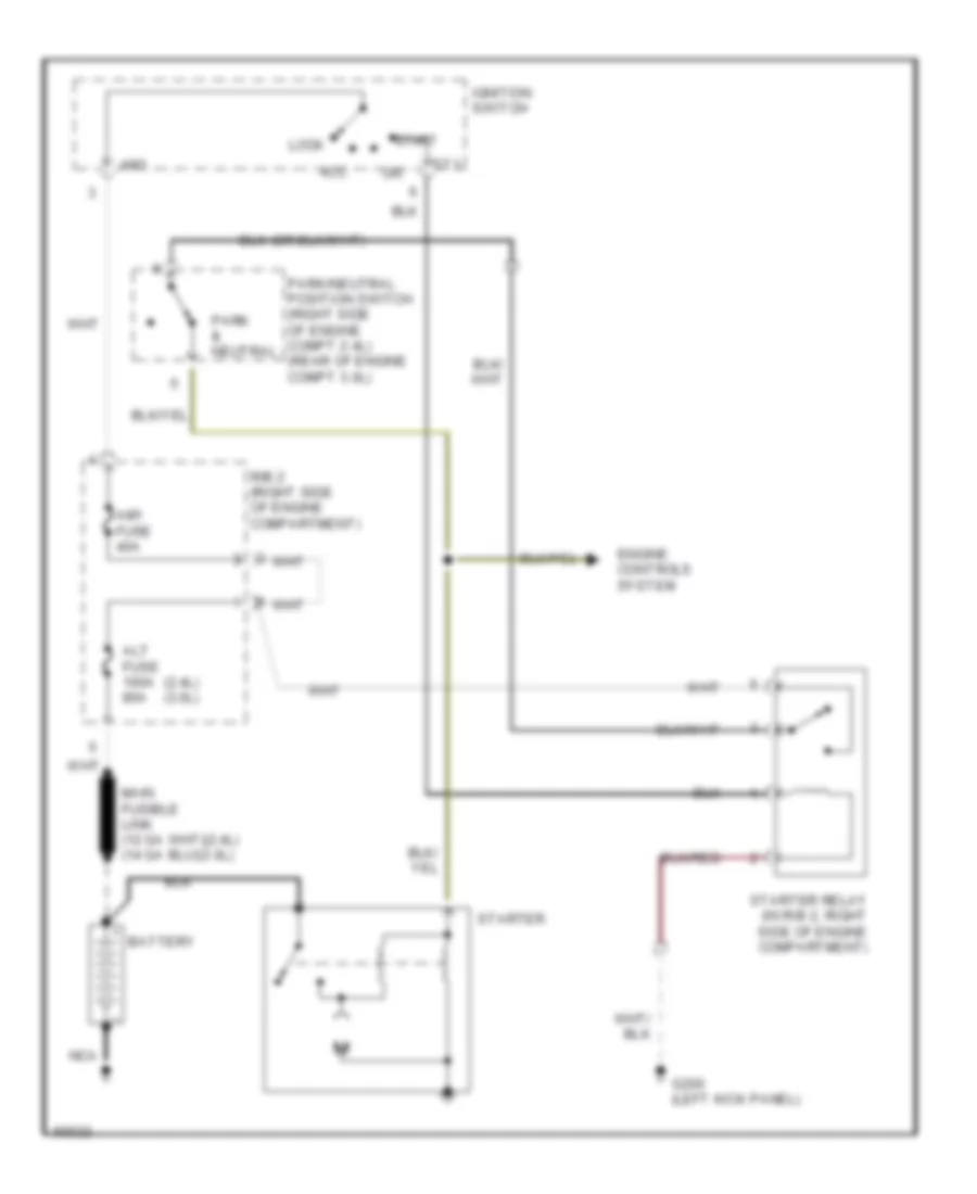
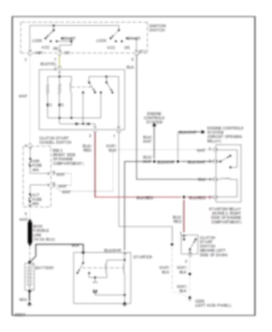
Starting Wiring Diagram, M/T for Toyota 4Runner SR5 1993
List of elements for Starting Wiring Diagram, M/T for Toyota 4Runner SR5 1993:
- Acc
- Alt fuse 80a
- Am1
- Am1 fuse 40a
- Battery
- Clutch start cancel switch
- Clutch start switch (behind left side of dash)
- Engine controls system
- Engine controls system (circuit opening relay)
- G200 (left kick panel)
- Ig1
- Ignition switch
- Lock
- Nca
- R/b 2 (right side of engine compartment)
- St1
- Start
- Starter
- Starter relay (in r/b 2, right side of engine compartment)
TRANSMISSION
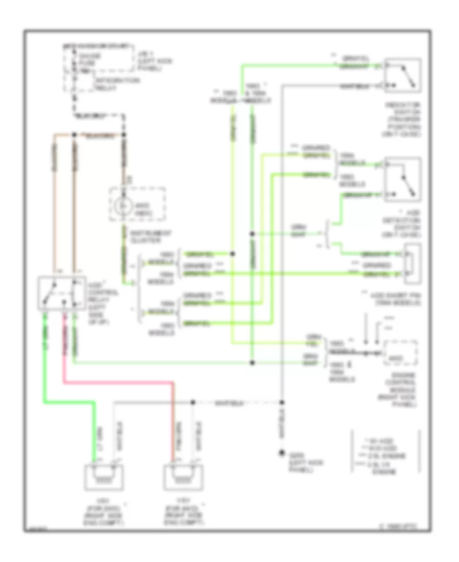
Transfer Case Wiring Diagram, A/T for Toyota 4Runner SR5 1993
List of elements for Transfer Case Wiring Diagram, A/T for Toyota 4Runner SR5 1993:
- * **
- * 2.4l eng.
- ** *
- ** 3.0l v6 engine
- 1995 vftc c
- 4wd
- 4wd indic.
- A/t parking indic.
- A10
- A12
- Add
- Add control relay (behind left i/p)
- Add detection switch (on add actuator, on front of differential)
- Diode (w/ add) (above right kick panel)
- E21
- Engine and electronic controlled transmission ecu (right kick panel)
- G200 (left kick panel)
- Gauge fuse 10a
- Hot in on or start
- Indicator switch (transfer position)
- Instrument cluster
- Integration relay
- J/b 1 (left kick panel)
- Models
- Park/neutral position switch (right side of transmission)
- Red
- Short pin
- Tho2
- Transfer case
- Transfer fluid temperature sensor
- Transfer neutral position switch (on t-case)
- Transfer oil pressure switch (for add)
- Vsv (2wd w/ add) (right eng compt)
- Vsv (4wd w/ add) (right eng compt)
- W/ add
- W/o
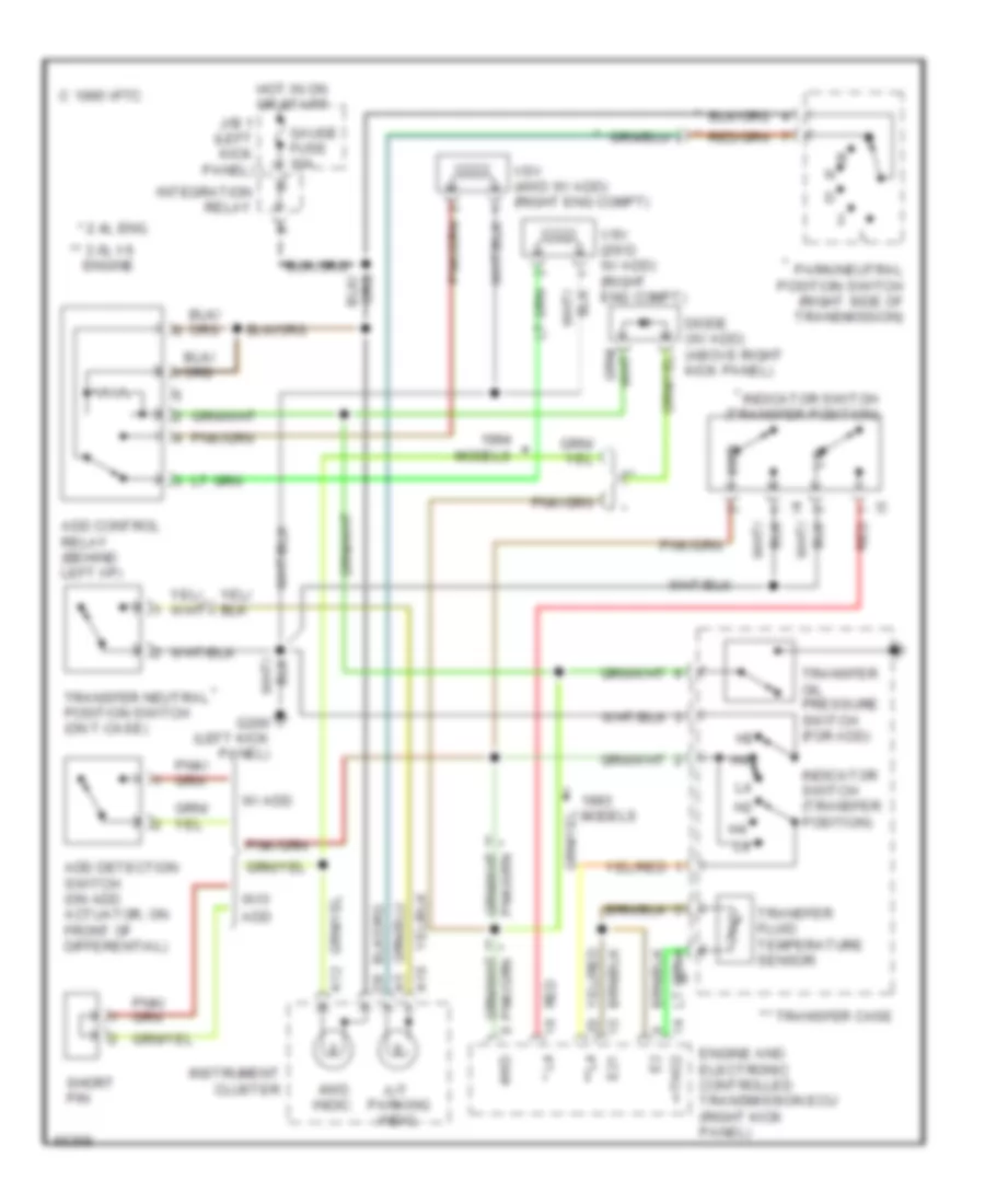
Transfer Case Wiring Diagram, M/T for Toyota 4Runner SR5 1993
List of elements for Transfer Case Wiring Diagram, M/T for Toyota 4Runner SR5 1993:
- & 1994 models
- (for 4wd) (right side eng compt)
- (left side of i/p)
- * w/ add
- ** w/o add
- ***
- *** ****
- *** 2.5l engine
- ****
- **** 3.0l v6
- 1993 & models
- 4wd
- 4wd indic.
- A12
- Add control relay
- Add detection switch (on t-case)
- Add short pin (1994 models)
- C 1995 vftc
- Engine
- Engine control module (right kick panel)
- G200 (left kick panel)
- Gauge fuse 10a
- Hot in on or start
- Indicator switch (tranfer position) (on t-case)
- Instrument cluster
- Integration relay
- J/b 1 (left kick panel)
- Models
- Vsv
- Vsv (for 2wd) (right side eng compt)
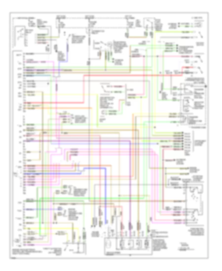
Transmission Wiring Diagram for Toyota 4Runner SR5 1993
List of elements for Transmission Wiring Diagram for Toyota 4Runner SR5 1993:
- (1994) **
- (4wd)
- (starter
- * **
- * w/ 2.4l
- ** *
- ** w/ 3.0l v6 engine
- +b1
- 1995 vftc c
- 2wd
- 4wd
- Add
- Add detection switch (on add actuator, on front of differential)
- Batt
- C17
- Cruise control system
- Data link connector 1 (right side eng compt)
- Dg te2 t e1
- E21
- Efi fuse 15a
- Efi main
- Electronic controlled transmission pattern select switch
- Electronic controlled transmission solenoid and vehicle speed sensor
- Engine
- Engine and electronic controlled transmission ecu (right kick panel)
- Engine controls system
- Engine coolant temperature sensor (on intake manifold)
- Exterior lights system
- G100 (front of left front fender)
- G117 (cam bearing cap)
- G120 (intake manifold)
- Gauge fuse 10a
- Hot at all times
- Hot in on or start
- Idl
- Ign fuse 7.5a
- Indicator switch (transfer position)
- Indicator switch (transfer position) (on t-case)
- Instrument cluster system
- Integration relay
- Interior lights system
- J/b 1 (left kick panel)
- Models
- N **
- No. 1
- No. 2
- No. 3
- No. 4
- Norm
- O/d main switch
- Od1
- Od2
- Oil
- Oil temperature sensor (right front trans pan)
- Oil temperature switch (right side eng compt)
- Park/neutral position switch (right side of transmission)
- Pin a12
- Pin a5
- Pin b6
- Pin c2 (not used)
- Pin c7
- Pin d2
- Pin d4
- Pwr
- R/b 2 (right eng compt)
- Red
- Relay
- Relay)
- Short pin
- Sp1
- Sp2
- Sta
- Starting/ charging system
- Stop fuse 15a
- Stop light switch (above brake pedal)
- Stp
- Te2
- Te2 th02
- Th01
- Throttle position sensor (on throttle body)
- Thw
- Transfer case
- Transfer fluid temperature sensor
- Transfer oil pressure switch (for add)
- Transmissions systems (a/t transfer case circuit)
- Vcc
- Vehicle speed sensor
- Vta
- W/ add
- W/o
WIPER/WASHER
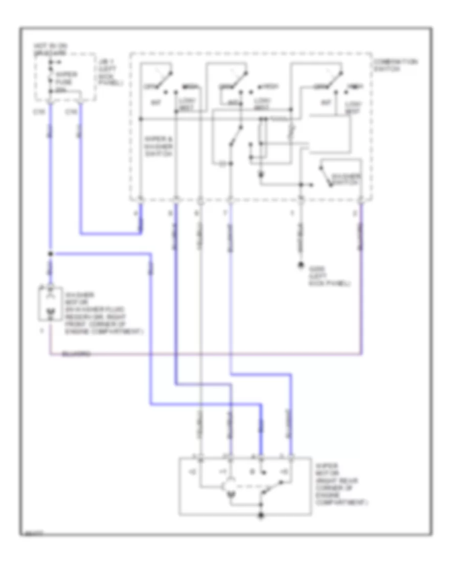
Front Wiper/Washer Wiring Diagram for Toyota 4Runner SR5 1993
List of elements for Front Wiper/Washer Wiring Diagram for Toyota 4Runner SR5 1993:
- C15
- C16
- Combination switch
- G200 (left kick panel)
- High
- Hot in on or start
- Int
- J/b 1 (left kick panel)
- Low/ mist
- Off
- Washer motor (in washer fluid reservoir, right front corner of engine compartment)
- Washer switch
- Wiper & washer switch
- Wiper fuse 20a
- Wiper motor (right rear corner of engine compartment)
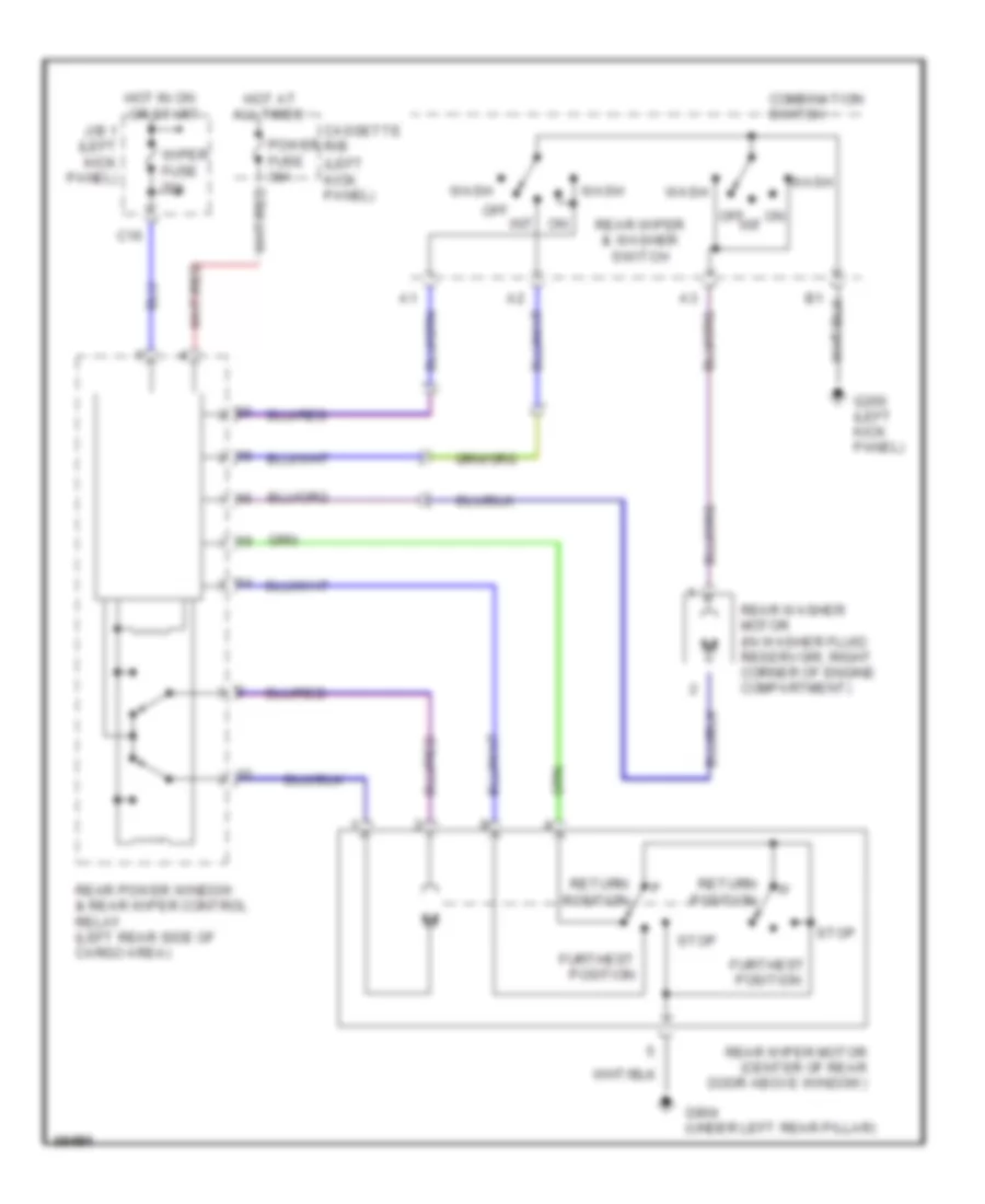
Rear Wiper/Washer Wiring Diagram for Toyota 4Runner SR5 1993
List of elements for Rear Wiper/Washer Wiring Diagram for Toyota 4Runner SR5 1993:
- (left kick panel)
- All times
- C16
- Cassette r/b
- Combination switch
- Furthest position
- G200 (left kick panel)
- G904 (under left rear pillar)
- Hot at
- Hot in on or start
- J/b 1 (left kick panel)
- Off
- On int
- Power fuse 30a
- Rear power window & rear wiper control relay (left rear side of cargo area)
- Rear washer motor (in washer fluid reservoir, right corner of engine compartment)
- Rear wiper & washer switch
- Rear wiper motor (center of rear door above window)
- Return position
- Stop
- Wash
- Wiper fuse 20a

 Čeština
 Dansk
Dansk Deutsch
 Ελληνικά
 English
 English
 Español
 Suomi
Suomi Français
 Français
 עברית
עברית Hrvatski
 Magyar
 日本語
日本語 한국어
한국어 Nederlands
 Polski
 Português
 Português
 Română
 Русский
 Slovenčina
 Slovenščina
 Svenska
 Türkçe
 中文 (中国)