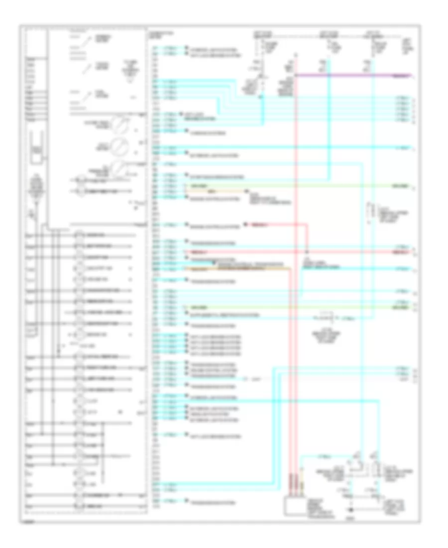
AIR CONDITIONING
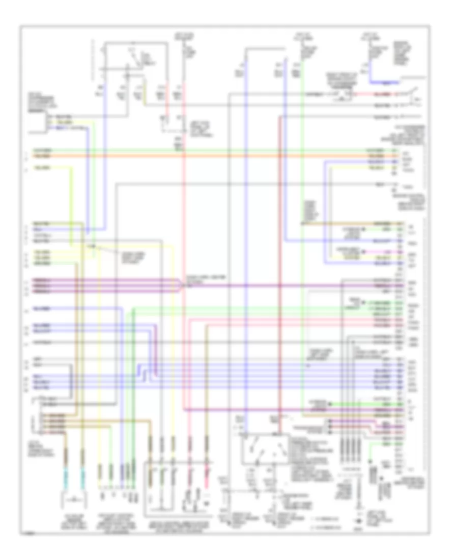
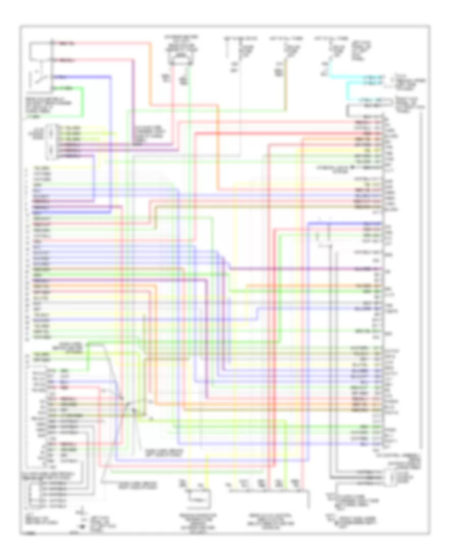
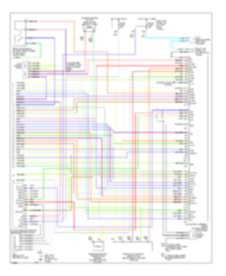
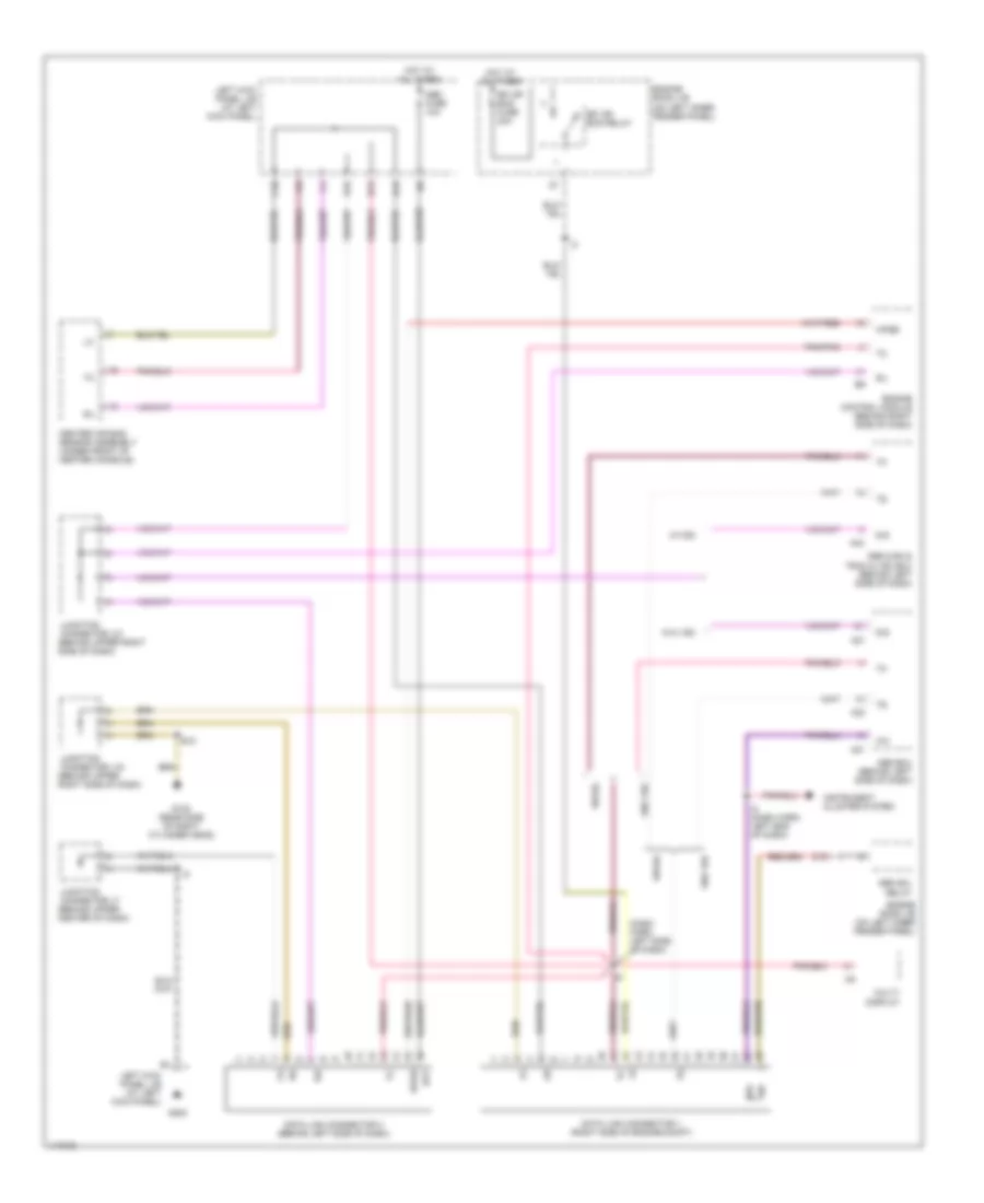
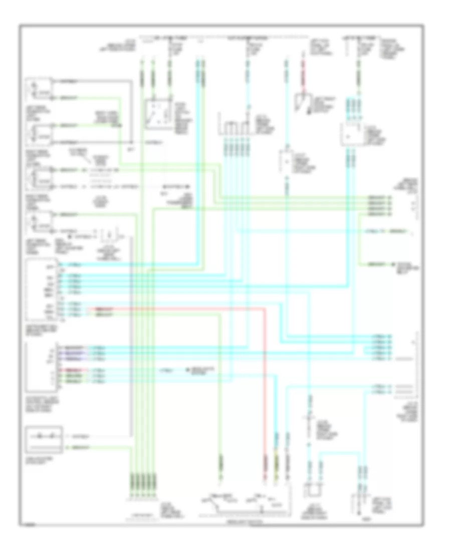
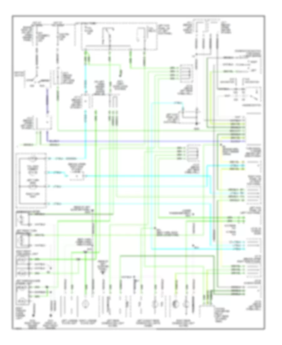
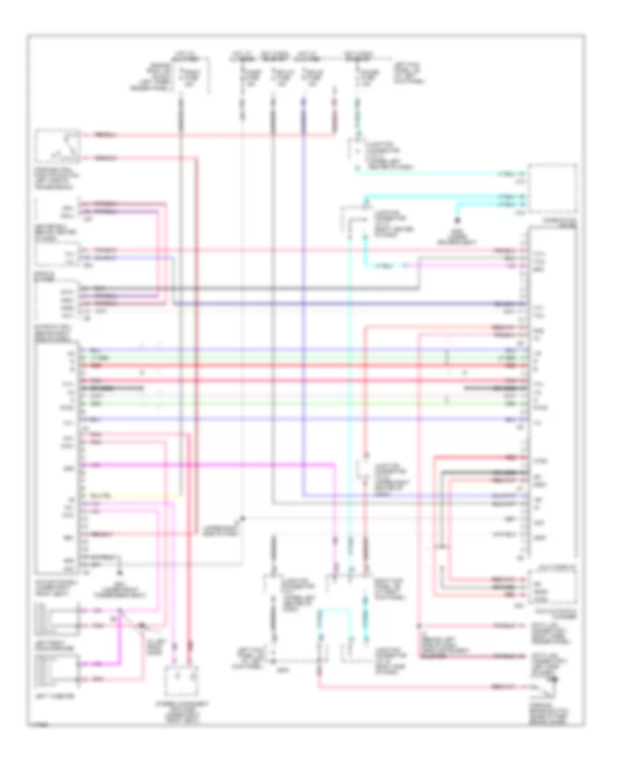
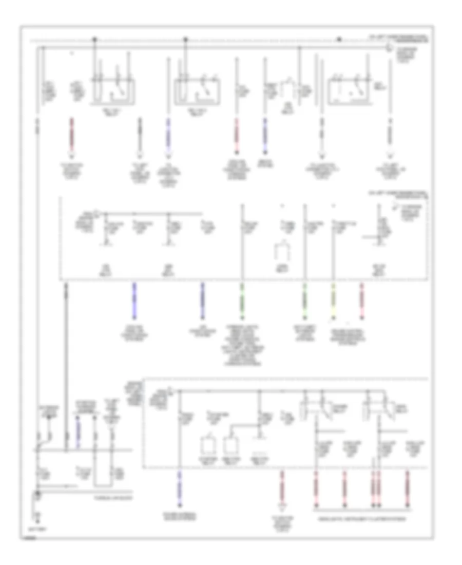
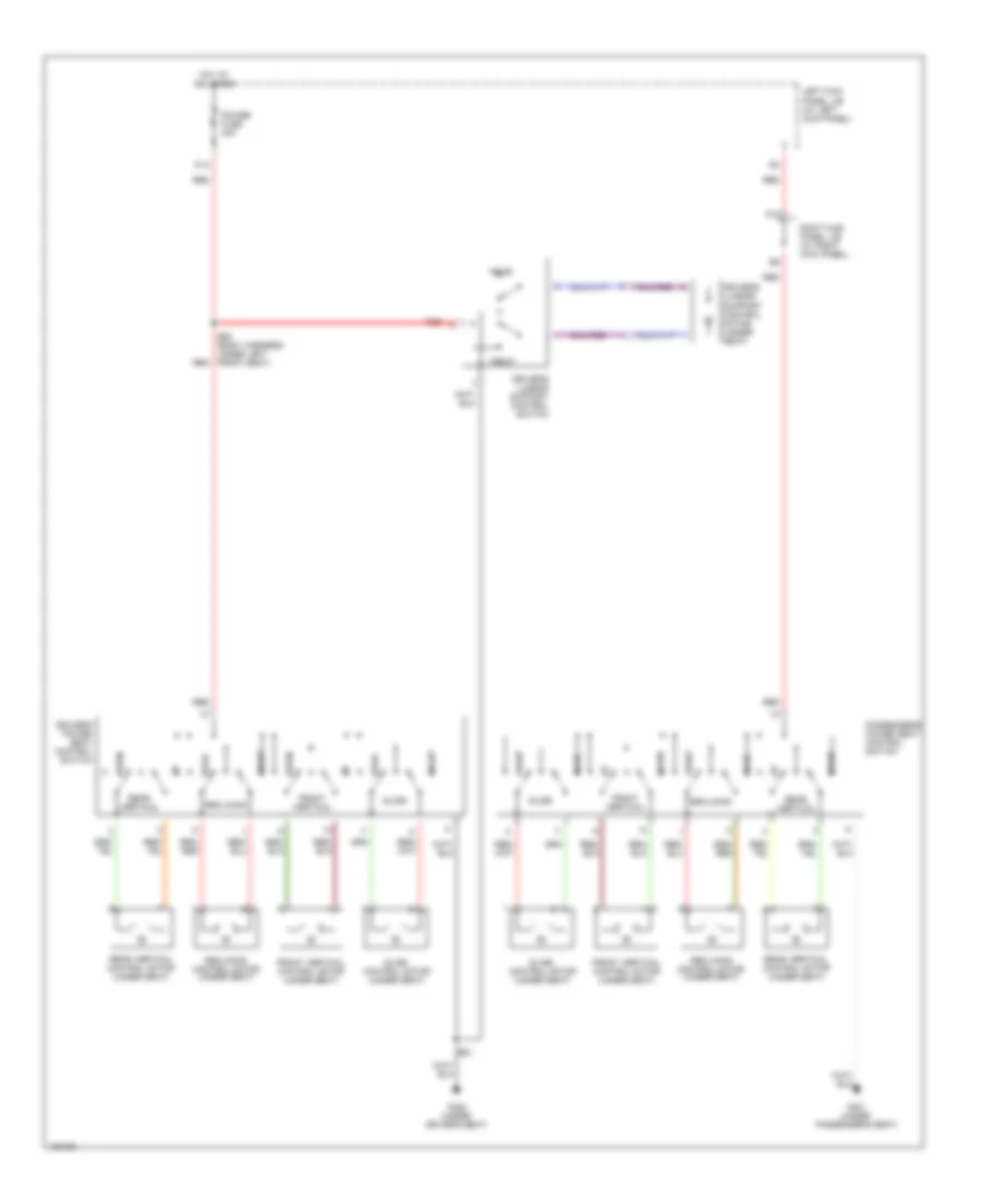
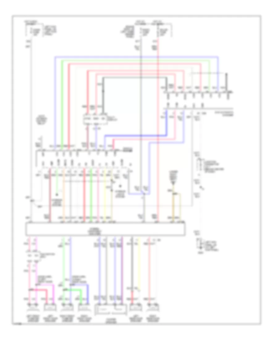
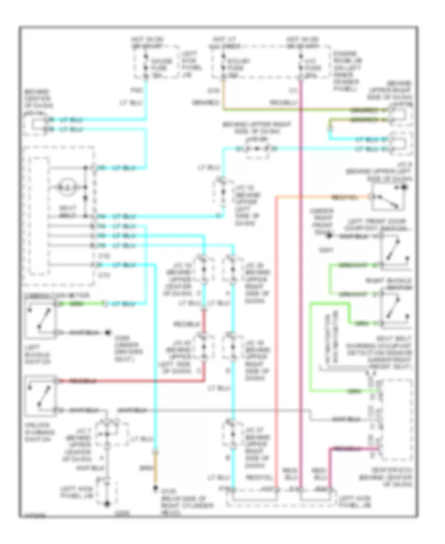
Front A/C Wiring Diagram, with Navigation (1 of 2) for Toyota Land Cruiser 2001
 https://portal-diagnostov.com/license.html
Automotive Electricians Portal FZCO
Automotive Electricians Portal FZCO
https://portal-diagnostov.com/license.html
https://portal-diagnostov.com/license.html
Automotive Electricians Portal FZCO
Automotive Electricians Portal FZCO
List of elements for Front A/C Wiring Diagram, with Navigation (1 of 2) for Toyota Land Cruiser 2001:
- (at right kick panel) right kick panel j/b
- (dash harn, right side of dash)
- (near right headlight) a/c ambient temperature sensor
- (under passenger's seat) g301
- A/c amplifier (rear) (on right side of cargo area)
- A/c thermistor (behind right side of dash)
- Ac1
- Air vent mode control servo motor (behind left center of dash, on heater-a/c housing)
- B/l
- Blower motor controller (behind lower right side of dash)
- C21
- C23
- C24
- Center ecu (behind center of dash)
- Cid
- Cigar fuse 15a
- Clk
- Control circuit
- Csd
- D22
- Def
- Dpd
- E12
- E21
- Ecu-b fuse 15a
- Engine room j/b (on left inner fender panel)
- F/d
- F10
- F11
- F12
- F13
- F14
- F15
- F16
- Face
- Foot
- Foot/def
- Frblw
- Frcid
- Frclk
- Frcsd
- Frhr
- Frlat
- Frs5
- Frte
- Frtp
- Frtr
- G200
- G203
- Gateway ecu (behind right side of dash)
- Gnd
- Gtx+
- Gtx-
- H10
- H11
- H12
- H13
- H14
- H15
- H16
- H17
- H18
- Hot at all times
- Hot in on or start
- Htr fuse 60a
- I10
- I11
- I12
- I13
- I14
- I5 (dash harn, behind combination meter)
- I54
- Ig1
- Ign
- J/c 22 (behind right side of dash)
- J/c 38 (in back door)
- J/c 39 (in back door)
- J/c 9 (behind upper left side of dash)
- L10
- Lat
- Left kick panel j/b (at left kick panel)
- Lock
- Mgc
- Mpd1
- Mpd2
- Mpx+
- Mpx-
- Mtr relay
- Multi- display
- Nca
- P26
- Position switches
- Rear a/c circuit
- Red
- Rhr
- Room temperature sensor (front) (behind left center of dash)
- Stx
- Swd
- Tam
- Tpi
- Tx3+
- Tx3-
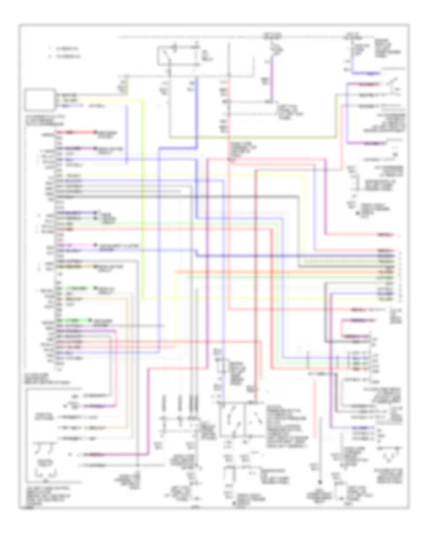
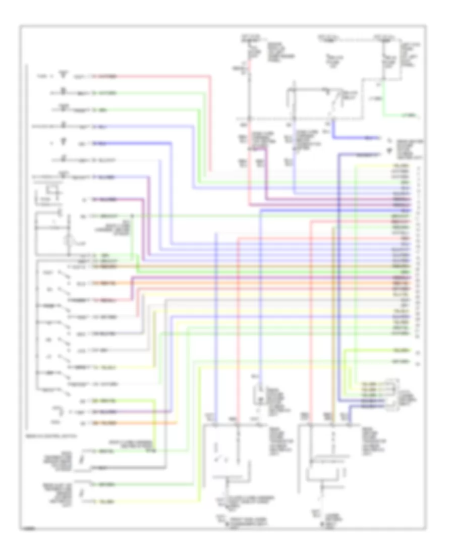
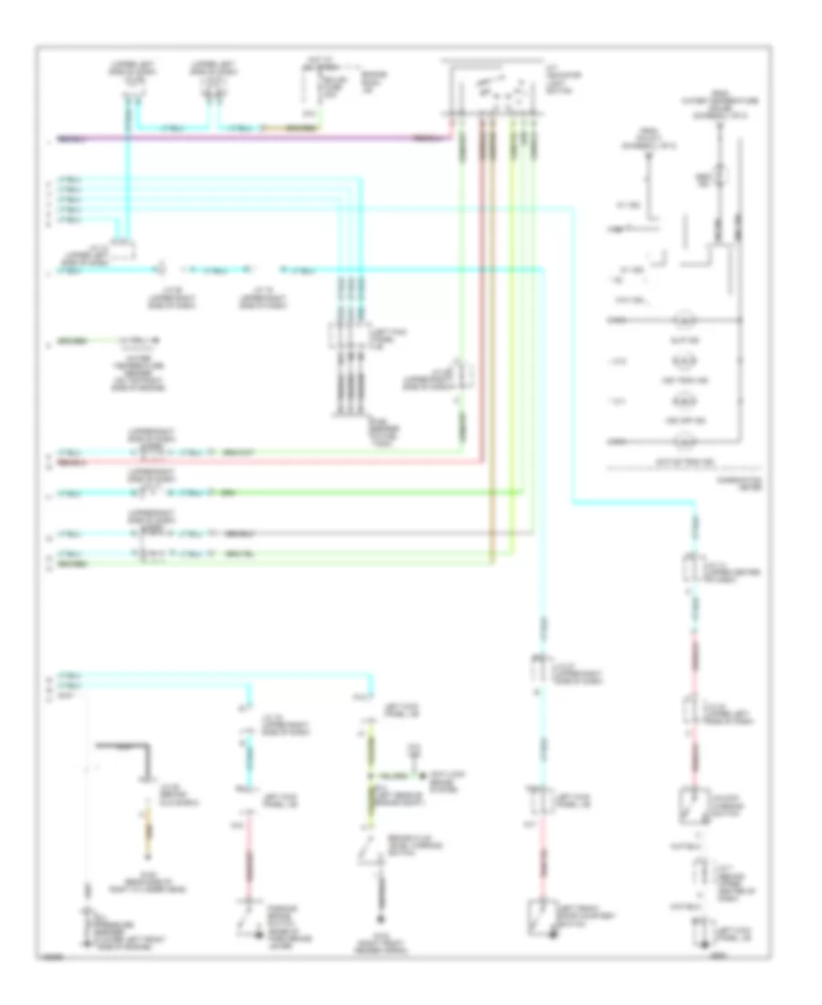
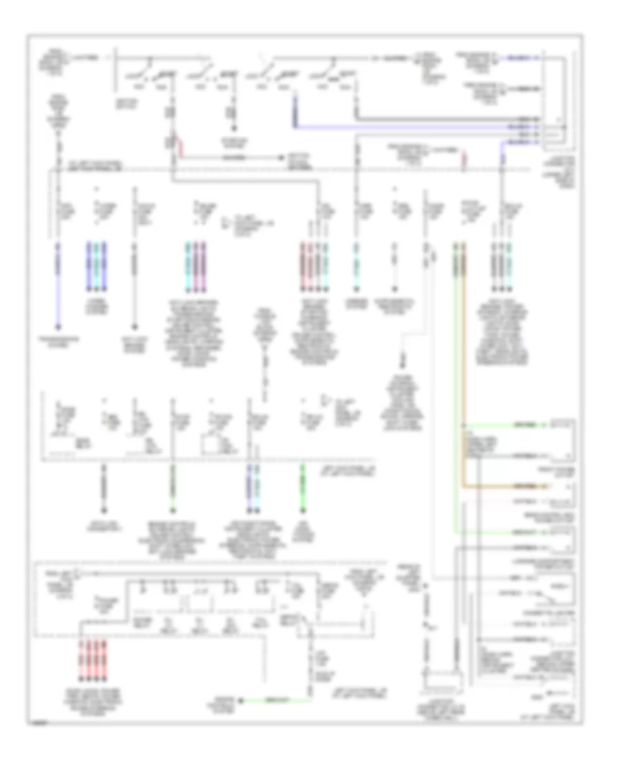
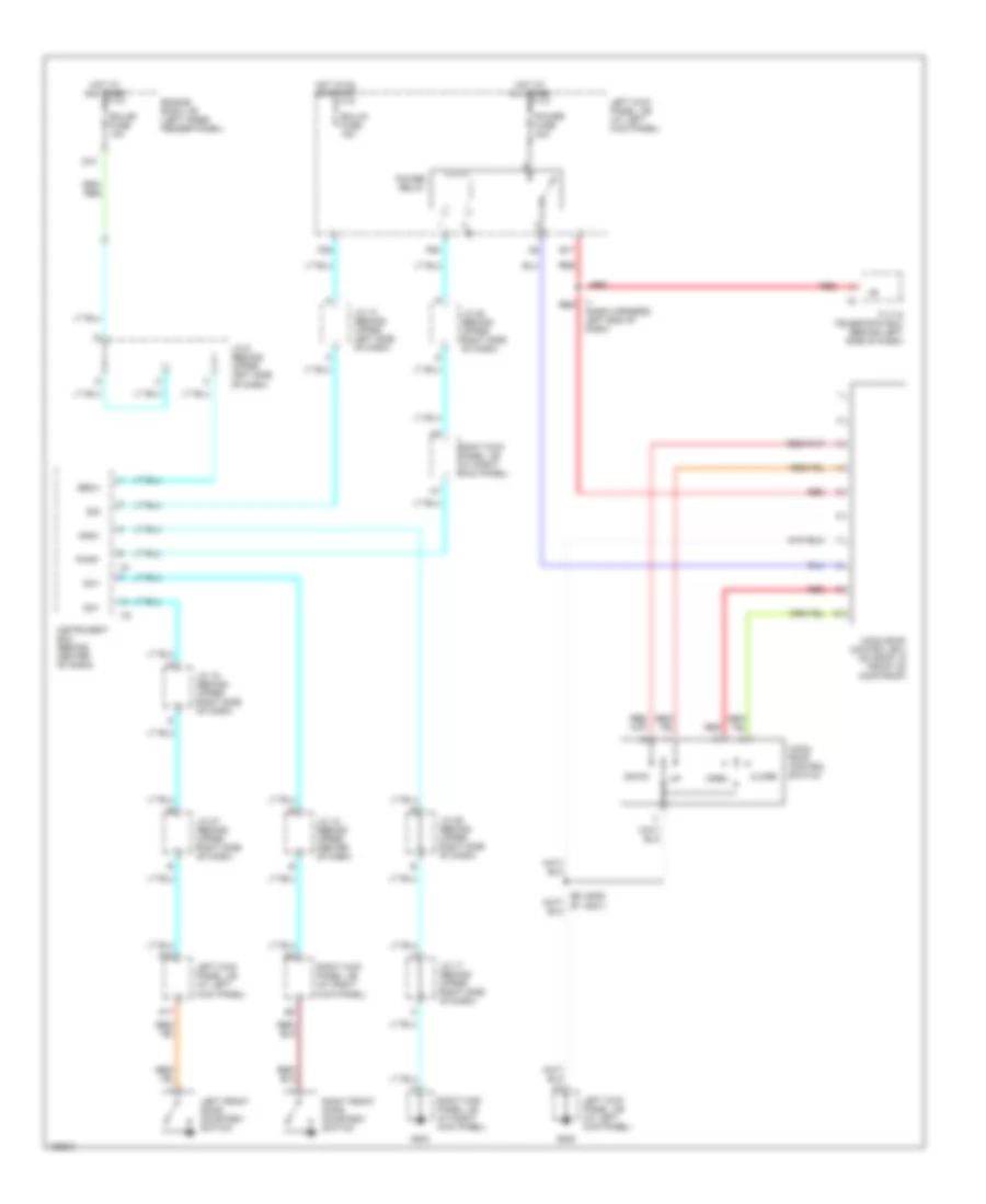
Front A/C Wiring Diagram, with Navigation (2 of 2) for Toyota Land Cruiser 2001
List of elements for Front A/C Wiring Diagram, with Navigation (2 of 2) for Toyota Land Cruiser 2001:
- (dash harn, center of dash) i10
- (dash harn, left side of dash)
- (dash harn, right side of dash)
- (dash harn, right side of dash) i11
- (front of right fender apron) g101
- (front of right fender apron) g103
- (on a/c compressor) a/c magnetic clutch & lock sensor
- (right front of engine compt) a/c condenser fan motor
- A/c
- A/c condenser fan relay (on left front of engine compartment, near headlight)
- A/c dual pressure switch (w/o rear a/c) a/c triple pressure switch (a/c dual & single pressure switch) (w/rear a/c) (left front of eng compartment, near headlight assembly)
- A/c fuse 20a
- A/c solar sensor (on top left side of dash)
- Acc
- Act
- Aif
- Air
- Air inlet control servo motor (behind right side of dash, on heater- a/c housing)
- Air mix control servo motor (behind right center of dash, on heater-a/c housing)
- B20
- C pnk
- C14
- C20
- C22
- Cds fan fuse 20a
- Center ecu (behind center of dash)
- Clk
- Cool
- D10
- Dpd
- E10
- E11
- E12
- E13
- E14
- E15
- E16
- E17
- E18
- E19
- E20
- Ecu-b1 fuse 20a
- Els2
- Engine control module (behind right side of dash)
- Engine room j/b (on left inner fender panel)
- Framc
- Framh
- G10
- G11
- G12
- G13
- G14
- G15
- G16
- G17
- G18
- G19
- G20
- G200
- G21
- G22
- Gnd
- Hot at all times
- Hot in on or start
- I10 (dash harn, left side of dash)
- I14
- Ig+
- Ill+
- Ill-
- Instrument cluster system
- Interior lights system
- J/c 44 (behind upper right side of dash)
- J/c 7 (behind upper center of dash)
- L13
- L14
- L15
- L17
- L19
- Left kick panel j/b (at left kick panel)
- Mfrs
- Mg clt relay
- Mrec
- Psw
- Rear a/c circuit
- Rrmgv
- Spd
- Stx
- Swd
- Tach
- Thwo
- Transmissions system
- Ver2
- Ver3
- W/ rear a/c
- W/o rear a/c
- Warm
- Warning systems
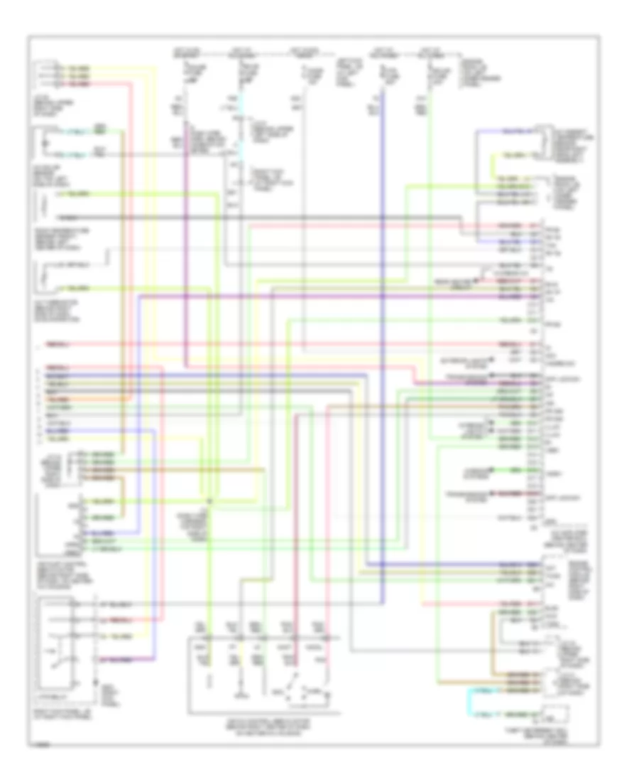
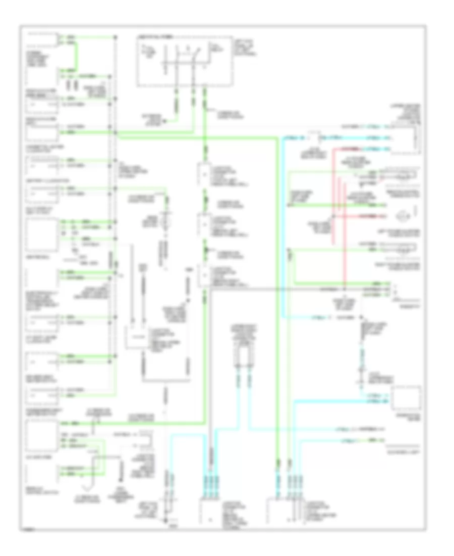
Front A/C Wiring Diagram, without Navigation (1 of 2) for Toyota Land Cruiser 2001
List of elements for Front A/C Wiring Diagram, without Navigation (1 of 2) for Toyota Land Cruiser 2001:
- (dash wire harn, behind combination meter)
- (dash wire harness, behind combination meter) i5
- (dash wire harness, top center of dash) i10
- (front right side of fender apron) g101
- (front right side of fender apron) g103
- A/c amplifier (center ecu) (behind center of dash)
- A/c amplifier (rear) (w/ rear a/c) (on right side of cargo area)
- A/c condenser fan motor (w/ rear a/c)
- A/c condenser fan relay (w/ rear a/c) (on left front of engine compartment)
- A/c dual pressure switch (w/o rear a/c) a/c triple pressure switch (a/c dual & single pressure switch) (w/rear a/c) (left front of engine compartment, near headlight assembly)
- A/c fuse 20a
- A/c magnetic clutch & lock sensor (on a/c compressor)
- A10
- A11
- A12
- A13
- A14
- A15
- A16
- A17
- A18
- A19
- A20
- A21
- A22
- A23
- A24
- A25
- A26
- Ac1
- Act
- Air vent mode control servo motor (behind left center of dash, on heater-a/c housing)
- B/l
- B10
- B11
- B12
- B13
- B14
- B15
- B16
- B20
- Blower motor controller (behind right side of dash)
- C14
- Cds fan fuse 20a
- Cid
- Clk
- Control circuit
- Csd
- Def
- Defogger system
- E11
- E19
- Engine room j/b (on left inner fender panel)
- F/d
- Face
- Foot
- Foot/ def
- Fr blw
- Fr cid
- Fr clk
- Fr csd
- Fr hr
- Fr lat
- G200
- G301 (under front passenger's seat)
- Gnd
- Hot at all times
- Hot in on or start
- I10 (dash wire harness, top center of dash)
- Ig1
- Ign
- Instrument cluster system
- J/c 38 (in back door)
- J/c 39 (in back door)
- J/c 7 (behind upper center of dash)
- L13
- L14
- L15
- L17
- L19
- Lat
- Left kick panel j/b (at left kick panel)
- Lock
- Mg clt relay
- Mgc
- Mrrhr
- Nca
- Position switches
- Psw
- Rdfgr
- Rear a/c circuit
- Rear heater circuit
- Red
- Rhfr
- Rhi-i
- Rhr
- Rlo-i
- Rr mgv
- Spd
- Ver1
- Ver2
- Ver3
- Ver4
- W/ rear a/c
- W/o rear a/c
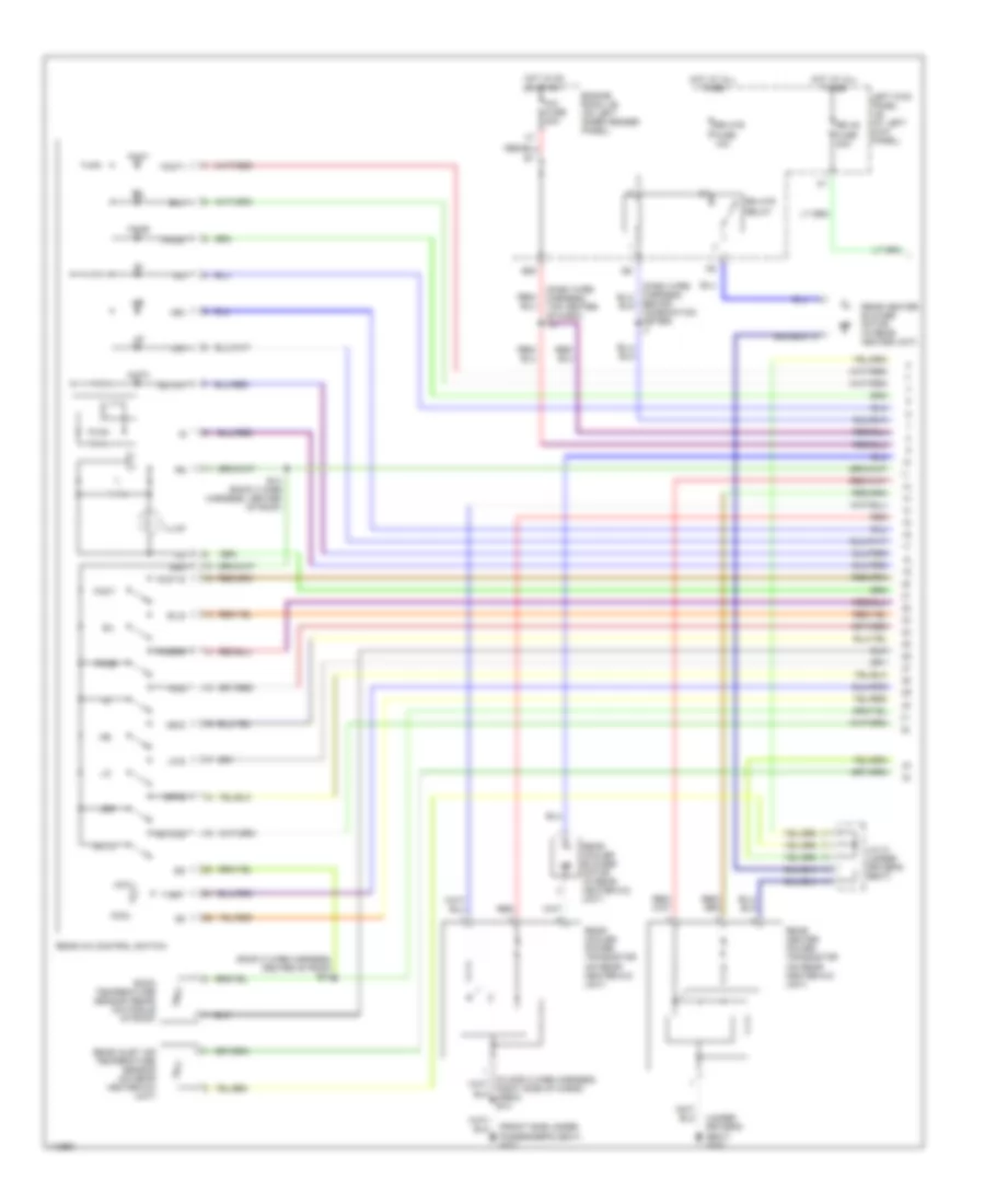
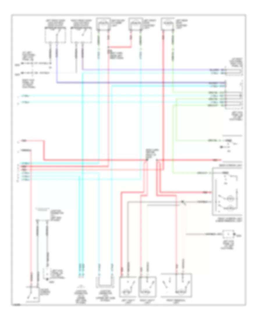
Front A/C Wiring Diagram, without Navigation (2 of 2) for Toyota Land Cruiser 2001
List of elements for Front A/C Wiring Diagram, without Navigation (2 of 2) for Toyota Land Cruiser 2001:
- A/c
- A/c ambient temperature sensor (near right headlight assembly)
- A/c amplifier (center ecu) (behind center of dash)
- A/c solar sensor (on top left side of dash)
- A/c thermistor (behind right side of dash, on evaporator)
- Acc
- Act
- Aif
- Air
- Air inlet control servo motor (behind right side of dash, on heater- a/c housing)
- Air mix control servo motor (behind right center of dash, on heater-a/c housing)
- C10
- C11
- C12
- Cigar fuse 15a
- Cool
- D10
- D11
- D12
- D13
- D14
- D15
- D16
- D17
- D18
- D19
- D20
- D21
- D22
- D25
- Diff lock sw
- E12
- E20
- E21
- E22
- Ecu-b fuse 15a
- Ecu-b1 fuse 20a
- Els2
- Engine control module (behind right side of dash)
- Engine room j/b (on left inner fender panel)
- Exterior lights system
- Fr amc
- Fr amh
- Fr s5
- Fr sg
- Fr te
- Fr tp
- Fr tr
- G203 (right kick panel)
- Gauge fuse 15a
- Gnd
- Hazard sw
- Hot at all times
- Hot in acc or on
- Hot in on or start
- Htr fuse 60a
- I-s/bw
- I-sec
- I14 (dash wire harness, top right side of dash)
- I5 (dash wire harn, behind combination meter)
- I54
- Illum
- Imld
- Ind
- Interior lights system
- J/c 21 (behind right side of dash)
- J/c 22 (behind upper right side of dash)
- J/c 44 (behind upper right side of dash)
- J/c 9 (behind upper left side of dash)
- L10
- Left kick panel j/b (at left kick panel)
- Mcool
- Mfrs
- Mhot
- Mrec
- Mtr relay
- P26
- Pnk
- Rear heater circuit
- Rh-s
- Right kick panel j/b (at right kick panel)
- Room temperature sensor (front) (behind left center of dash)
- Tach
- Tam
- Theft deterrent ecu (behind center of dash)
- Thwo
- Tpi
- Transmissions system
- W/o rear a/c
- Warm
- Warning systems
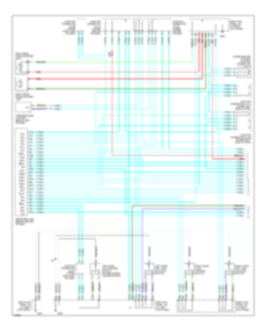
Rear A/C Wiring Diagram, with Navigation (1 of 2) for Toyota Land Cruiser 2001
List of elements for Rear A/C Wiring Diagram, with Navigation (1 of 2) for Toyota Land Cruiser 2001:
- (dash wire harness, top center of dash) i10
- (front side under passenger's seat) g301
- (roof 2 wire harness, center of roof) b13
- (under driver's seat) g300
- A/c fuse 20a
- Auto
- Auto-1
- Auto-s
- B/l
- B/l-i
- B/ls
- B13 (roof 2 wire harness, center of roof)
- B20
- Behind combination meter) i7
- Cool
- Engine room j/b (on left inner fender panel)
- Face
- Face-i
- Face-s
- Foot
- Foot-i
- Foot-s
- Hi-i
- Hi-s
- Hot
- Hot at all times
- Hot in on or start
- Ill
- Illum
- J/c 31 (under driver's seat)
- Left kick panel j/b (at left kick panel)
- Lo-i
- Lo-s
- Me-i
- Me-s
- Off
- Off-s
- Rear a/c control switch
- Rear cooler blower motor (in rear heater-a/c unit)
- Rear cooler power transistor (on rear heater-a/c unit)
- Rear heater blower motor (in rear heater unit)
- Rear heater power transistor (on rear heater-a/c unit)
- Rear inlet air temperature sensor (on rear heater-a/c unit)
- Red
- Room temperature sensor (rear) (on middle of roof)
- Rr ac fuse 30a
- Rr htr fuse 10a
- Rr htr relay
- Srg
- T-set
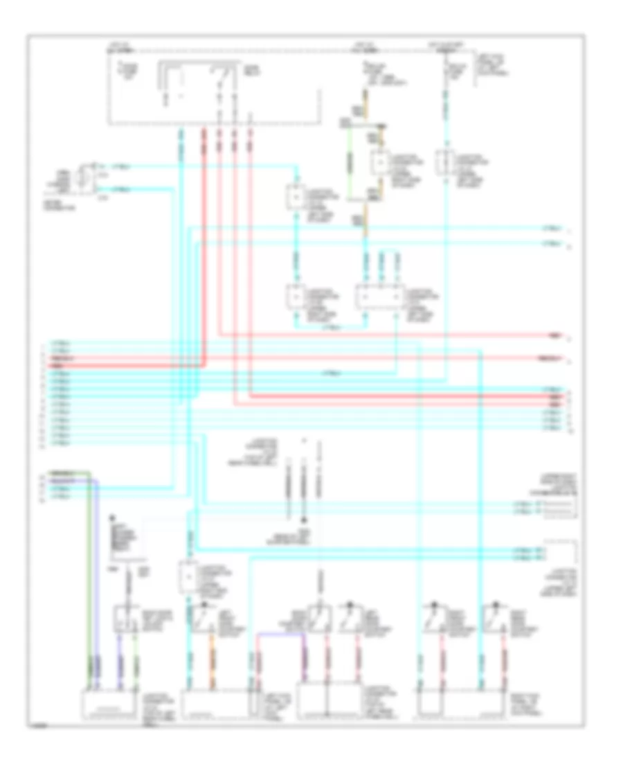
Rear A/C Wiring Diagram, with Navigation (2 of 2) for Toyota Land Cruiser 2001
List of elements for Rear A/C Wiring Diagram, with Navigation (2 of 2) for Toyota Land Cruiser 2001:
- (a/c sub wire harness, right side of cargo area) b19
- (dash harn, behind center of dash)
- (dash harn, behind left side of dash)
- (dash harn, behind right side of dash)
- (front side under passengers seat) g301
- (on rear heater- a/c unit) rear cooler magnetic valve
- A/c amplifier (center ecu) (behind center of dash)
- A/c control assembly (rear) (on right side of cargo area)
- A10
- A11
- A12
- A13
- A14
- A15
- A16
- A17
- A18
- A19
- A20
- A21
- A22
- A32
- A33
- A34
- Acc
- Auto-1
- Auto-s
- B/l-1
- B/l-s
- B10
- B11
- B12
- Blwrc
- Blwrh
- C10
- C11
- C12
- C13
- C14
- C15
- C16
- C17
- C18
- C20
- C21
- C22
- Cid
- Cigar fuse 15a
- Clk
- Csd
- D10
- D22
- E10
- E11
- E21
- Ecu-b fuse 15a
- Ecu-b1 fuse 20a
- F15
- F16
- Face-i
- Face-s
- Foot-1
- Foot-s
- Fr cid
- Fr clk
- Fr csd
- Fr lat
- G11
- G12
- G13
- G15
- G200
- G21
- G22
- Gnd
- Hi-i
- Hi-s
- Hot at all times
- Hot in acc or on
- Hrrc
- Hrrh
- I10
- I15
- I54
- Ig+
- Ig1
- Ig2
- Ill+1
- Ill+2
- Interior lights system
- J/c 38 (in back door)
- J/c 39 (in back door)
- J/c 7 (behind top center of dash)
- J/c 9 (behind upper left side of dash)
- Lat
- Left kick panel j/b (at left kick panel)
- Lo-1
- Lo-s
- Mcr
- Me-1
- Me-s
- Mhr
- Nca
- Off-s
- P26
- Rear a/c mix control servo motor (below rear of center console)
- Rear cooler relay (on right rear corner of vehicle, in cargo area)
- Rear evaporator temperature sensor (on rear heater- a/c unit)
- Red
- Right kick panel j/b (at right kick panel)
- Rr mgv
- S51
- S52
- Sg1
- Sg2
- Ter
- Tinr
- Tpr
- Trr
- Tsetr
- Ver2
- Ver3
- Vmrc
- Vmrh
Rear A/C Wiring Diagram, without Navigation (1 of 2) for Toyota Land Cruiser 2001
List of elements for Rear A/C Wiring Diagram, without Navigation (1 of 2) for Toyota Land Cruiser 2001:
- (dash wire harness, top center of dash) i10
- (front side under passenger's seat) g301
- (roof 2 wire harness, center of roof) b13
- (under driver's seat) g300
- A/c fuse 20a
- Auto
- Auto-1
- Auto-s
- B/l
- B/l-i
- B/ls
- B13 (roof 2 wire harness, center of roof)
- B20
- Behind combination meter) i7
- Cool
- Engine room j/b (on left inner fender panel)
- Face
- Face-i
- Face-s
- Foot
- Foot-i
- Foot-s
- Hi-i
- Hi-s
- Hot
- Hot at all times
- Hot in on or start
- Ill
- Illum
- J/c 31 (under driver's seat)
- Left kick panel j/b (at left kick panel)
- Lo-i
- Lo-s
- Me-i
- Me-s
- Off
- Off-s
- Rear a/c control switch
- Rear cooler blower motor (in rear heater-a/c unit)
- Rear cooler power transistor (on rear heater-a/c unit)
- Rear heater blower motor (in rear heater unit)
- Rear heater power transistor (on rear heater-a/c unit)
- Rear inlet air temperature sensor (on rear heater-a/c unit)
- Red
- Room temperature sensor (rear) (on middle of roof)
- Rr ac fuse 30a
- Rr htr fuse 10a
- Rr htr relay
- Srg
- T-set
Rear A/C Wiring Diagram, without Navigation (2 of 2) for Toyota Land Cruiser 2001
List of elements for Rear A/C Wiring Diagram, without Navigation (2 of 2) for Toyota Land Cruiser 2001:
- (a/c sub wire harness, right side of cargo area) b19
- (front side under passengers seat) g301
- (on rear heater- a/c unit) rear cooler magnetic valve
- A/c amplifier (center ecu) (behind center of dash)
- A/c control assembly (rear) (on right side of cargo area)
- A10
- A11
- A12
- A13
- A14
- A15
- A16
- A17
- A18
- A19
- A20
- A21
- A22
- A25
- A32
- A33
- A34
- Acc
- Auto-1
- Auto-s
- B/l-1
- B/l-s
- B10
- B11
- B12
- Blwrc
- Blwrh
- C10
- C11
- C12
- C13
- C14
- C15
- C16
- C17
- C18
- Cid
- Cigar fuse 15a
- Clk
- Csd
- D12
- D22
- E21
- Ecu-b fuse 15a
- Face-i
- Face-s
- Foot-1
- Foot-s
- Fr cid
- Fr clk
- Fr csd
- Fr lat
- G200
- Gnd
- Hi-i
- Hi-s
- Hot at all times
- Hot in acc or on
- Hrrc
- Hrrh
- I54
- Ig1
- Ig2
- Ill+1
- Ill+2
- Interior lights system
- J/c 38 (in back door)
- J/c 39 (in back door)
- J/c 7 (behind top center of dash)
- J/c 9 (behind upper left side of dash)
- Lat
- Left kick panel j/b (at left kick panel)
- Lo-1
- Lo-s
- Mcr
- Me-1
- Me-s
- Mhr
- Nca
- Off-s
- P26
- Rear a/c mix control servo motor (below rear of center console)
- Rear cooler relay (on right rear corner of vehicle, in cargo area)
- Rear evaporator temperature sensor (on rear heater- a/c unit)
- Red
- Right kick panel j/b (at right kick panel)
- Rr mgv
- S51
- S52
- Sg1
- Sg2
- Ter
- Tinr
- Tpr
- Trr
- Tsetr
- Ver1
- Ver2
- Ver3
- Ver4
- Vmrc
- Vmrh
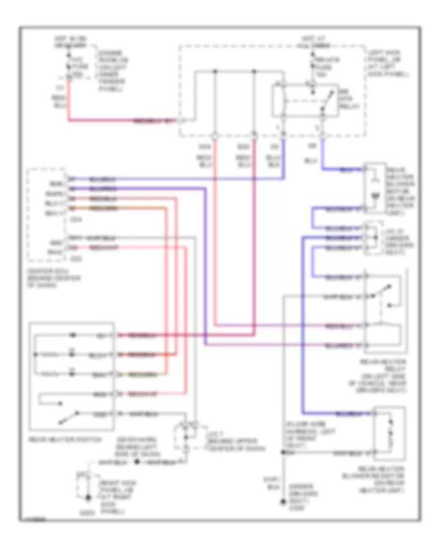
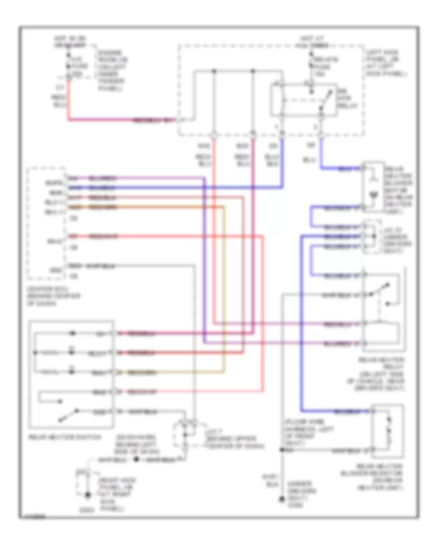
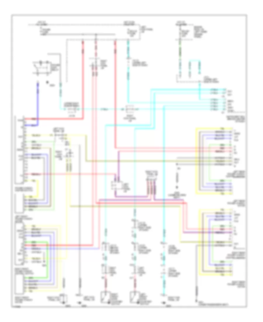
Rear Heater Wiring Diagram, with Navigation for Toyota Land Cruiser 2001
List of elements for Rear Heater Wiring Diagram, with Navigation for Toyota Land Cruiser 2001:
- (dash harn, behind left side of dash) i5
- (floor wire harness, left of front seat) b4
- (under driver's seat) g300
- A/c fuse 20a
- B20
- C22
- C24
- Center ecu (behind center of dash)
- Engine room j/b (on left inner fender panel)
- G11
- G203
- Gnd
- Hot at all times
- Hot in on or start
- Ig+
- J/c 31 (under driver's seat)
- J/c 7 (behind upper center of dash)
- Left kick panel j/b (at left kick panel)
- N18
- Rear heater blower motor (in rear heater unit)
- Rear heater blower resistor (on rear heater unit)
- Rear heater relay (on left side of vehicle, near driver's seat)
- Rear heater switch
- Rh-s
- Rh1-1
- Rhfr
- Rhi-i
- Rhr
- Rhs
- Right kick panel j/b (at right kick panel)
- Rlo-1
- Rr htr fuse 10a
- Rr htr relay
Rear Heater Wiring Diagram, without Navigation for Toyota Land Cruiser 2001
List of elements for Rear Heater Wiring Diagram, without Navigation for Toyota Land Cruiser 2001:
- (dash harn, behind left side of dash) i5
- (floor wire harness, left of front seat) b4
- (under driver's seat) g300
- A/c fuse 20a
- A16
- A17
- A26
- B20
- Center ecu (behind center of dash)
- D22
- Engine room j/b (on left inner fender panel)
- G203
- Gnd
- Hot at all times
- Hot in on or start
- Ig+
- J/c 31 (under driver's seat)
- J/c 7 (behind upper center of dash)
- Left kick panel j/b (at left kick panel)
- N18
- Rear heater blower motor (in rear heater unit)
- Rear heater blower resistor (on rear heater unit)
- Rear heater relay (on left side of vehicle, near driver's seat)
- Rear heater switch
- Rh-s
- Rh1-1
- Rhfr
- Rhi-i
- Rhr
- Rhs
- Right kick panel j/b (at right kick panel)
- Rlo-1
- Rr htr fuse 10a
- Rr htr relay
ANTI-LOCK BRAKES
Anti-lock Brake Wiring Diagrams, with VSC (1 of 3) for Toyota Land Cruiser 2001
List of elements for Anti-lock Brake Wiring Diagrams, with VSC (1 of 3) for Toyota Land Cruiser 2001:
- (engine harn, left rear corner of engine compt) e14
- A37
- A38
- A39
- A40
- A41
- A44
- Abs & ba & trac & vsc actuator
- Abs & ba & trac & vsc ecu (behind left side of dash)
- Abs 1 fuse 50a
- Abs 2 fuse 40a
- Abs mtr 1 relay
- Abs mtr 2 relay
- Abs sol relay
- Ast
- B10
- B11
- B12
- B14
- Braided
- E13
- E13 (engine harn, left fender apron)
- Engine controls system
- Engine room j/b (on left inner fender panel)
- Fl+
- Fl-
- Fr+
- Fr-
- Fss
- G103 (right front fender apron)
- Gnd1
- Gnd2
- Hot at all times
- Hot in run or start
- I2 (dash harn, left end of dash)
- Ig2
- Ign fuse 10a
- Left kick panel j/b (at left kick panel)
- Mr1
- Mr2
- Mss
- Mt+
- Mt-
- Mtt
- P10
- Pmc
- Pnk
- R1+
- R2+
- Red
- Sa1
- Sa2
- Sa3
- Sflh
- Sflr
- Sfrh
- Sfrr
- Srlh
- Srlr
- Srrh
- Srrr
- Str
- Vcm
Anti-lock Brake Wiring Diagrams, with VSC (2 of 3) for Toyota Land Cruiser 2001
List of elements for Anti-lock Brake Wiring Diagrams, with VSC (2 of 3) for Toyota Land Cruiser 2001:
- Ahc-ig fuse 20a
- B10
- Braided
- Ecu-ig fuse 15a
- G200
- Gauge fuse 15a
- Hot at all times
- Hot in run or start
- I34
- J/c 14 (behind upper center of dash)
- J/c 19 (behind upper right side of dash)
- J/c 23 (behind glove box)
- J/c 42 (behind left side of dash)
- J/c 44 (behind upper right side of dash)
- Left front abs speed sensor
- Left kick panel j/b (at left kick panel)
- Left rear abs speed sensor
- Master cylinder pressure sensor (on brake master cylinder)
- N15
- O12
- P83
- Park/ neutral position switch (on left side of trans- mission)
- Parking brake switch (on base of park brake lever)
- Pmc
- Pnk
- Red
- Right front abs speed sensor
- Right kick panel j/b (at right kick panel)
- Right rear abs speed sensor
- Rss
- Ss1+
- Ss1-
- Steering angle sensor (behind left side of dash)
- Stop fuse 15a
- Stoplight switch (on bracket, above brake pedal)
- Vcm
- Vsc warning buzzer (behind left side of dash)
Anti-lock Brake Wiring Diagrams, with VSC (3 of 3) for Toyota Land Cruiser 2001
List of elements for Anti-lock Brake Wiring Diagrams, with VSC (3 of 3) for Toyota Land Cruiser 2001:
- A42
- A43
- Abs & ba & trac & vsc ecu (behind left side of dash)
- Abs deceleration sensor (below rear of center console)
- Abs ind
- Active trac ind
- Braided
- Brake ind
- Brl
- C12
- C14
- C15
- Combination meter
- Computer data lines system
- D/g
- Data link connector 3 (behind left side of dash)
- E14
- Eng+
- Eng-
- Engine control module (behind right side of dash)
- Exi
- Exi3
- G103 (right front fender apron)
- G120 (rear side of right cyl head)
- Ggnd
- Gl1
- Gl2
- Gnd3
- Gnd4
- Gss
- Gyaw
- I5 (behind left side of dash)
- Ig1
- Ind
- Infr
- J/c 21 (behind upper right side of dash)
- J/c 28 (behind upper right side of dash)
- J/c 42 (behind left side of dash)
- Left kick panel j/b (at left kick panel)
- Neo
- P12
- P41
- P46
- Pkb
- Pnk
- Red
- Rl+
- Rl-
- Rr+
- Rr-
- Rss
- Sil
- Slip ind
- Ss1+
- Ss1-
- Stp
- Tfn
- Transfer neutral position detection switch (on left side of trans- mission)
- Transmissions system (center diff lock detection sw)
- Transmissions system (transfer l position detection sw)
- Trc+
- Trc-
- Vgs
- Vsc off ind
- Vsc trac ind
- Vscw
- Vys
- Yaw
- Yaw rate sensor (under center of dash, on transmission tunnel)
- Yaw2
- Yss
Anti-lock Brake Wiring Diagrams, without VSC (1 of 2) for Toyota Land Cruiser 2001
List of elements for Anti-lock Brake Wiring Diagrams, without VSC (1 of 2) for Toyota Land Cruiser 2001:
- (1998-99) (2000-01)
- A10
- A11
- A21
- A23
- Abs 1 fuse 40a 50a
- Abs 2 fuse 40a
- Abs actuator (on left rear corner of engine compt)
- Abs ecu (behind left side of dash)
- Abs mtr 1 relay
- Abs mtr 2 relay
- Abs sol relay
- B10
- B11
- B12
- B14
- Brake fluid level warning switch
- D/g
- D16
- E14
- Ecu-ig fuse 15a
- Engine controls system
- Engine room j/b (on left inner fender panel)
- Fl+
- Fl-
- Fr+
- Fr-
- G102
- G103 (right front fender apron)
- Grd1
- Grd2
- Grd3
- Grd4
- Hot at all times
- Hot in start or run
- I2 (dash harn, left end of dash)
- Ig1
- Ig2
- Ign fuse 10a
- J/c 2 (left end of dash)
- J/c 21 (behind glove box)
- Left kick panel j/b (at left kick panel)
- Mr1
- Mr2
- Mt+
- Mt-
- Pnk
- R1+
- R2+
- Red
- Sa1
- Sa2
- Sflh
- Sflr
- Sfrh
- Sfrr
- Srh
- Srr
- Stp
Anti-lock Brake Wiring Diagrams, without VSC (2 of 2) for Toyota Land Cruiser 2001
List of elements for Anti-lock Brake Wiring Diagrams, without VSC (2 of 2) for Toyota Land Cruiser 2001:
- (on bracket, above brake pedal) stoplight switch
- (right side of engine compt) data link connector 1
- A22
- Abs deceleration sensor (below front of center console)
- Abs ecu (behind left side of dash)
- Abs indic
- B10
- Braided
- Brake indic
- Brl
- C12
- C13
- C15
- Center differential lock control relay (behind right side of dash)
- Combi- nation meter
- Data link connector 3 (behind left side of dash, right of steering column)
- Detection switch (l position) (left side of transmission)
- E14 (engine harn, left fender apron)
- Engine control module (behind right side of dash)
- Exi
- Exi2
- Exi3
- G103 (right front fender apron)
- G120 (rear side of right cylinder head)
- Gauge fuse 15a
- Ggrd
- Gl1
- Hot at all times
- Hot in start or run
- I15 (dash harn, right end of dash)
- I2 (dash harn, left end of dash)
- I5 (behind left side of dash)
- J/c 14 (behind left side of dash)
- J/c 2 (left end of dash)
- J/c 28 (behind glove box)
- J/c 35 (left rear wheelwell)
- J/c 43 (behind upper left side of dash)
- J10
- Left front abs speed sensor (on inside of left front wheel)
- Left kick panel j/b (at left kick panel)
- Left rear abs speed sensor (on inside of left rear wheel)
- O12
- P10
- P11
- P12
- P83
- Pnk
- Rear differential lock control ecu (right kick panel)
- Red
- Right front abs speed sensor (on inside of right front wheel)
- Right kick panel j/b (at right kick panel)
- Right rear abs speed sensor (on inside of right rear wheel)
- Rl+
- Rl-
- Rr+
- Rr-
- Stop fuse 15a
- Transmssions system
- Vgs
ANTI-THEFT
Forced Entry Wiring Diagram (1 of 3) for Toyota Land Cruiser 2001
List of elements for Forced Entry Wiring Diagram (1 of 3) for Toyota Land Cruiser 2001:
- (behind left of dash) (w/ keyless entry system) wireless door lock ecu
- (behind left side of dash) j/c 1
- (behind upper right side of dash) j/c 28
- A - i19 b - i20 c - i21
- A10
- A11
- A14
- A20
- Acy
- B12
- B13
- B14
- B18
- Becu
- C11
- Cty
- Dcy
- Ddry
- Disw
- Dkl
- Dku
- Dlry
- Dml
- Dmu
- Dury
- Exterior lights system
- G16
- G17
- G18
- G19
- G200
- G203
- Gnd
- Gnd1
- I39
- I46
- I66
- I67
- I68
- I69
- Instrument ecu (behind center of dash)
- J/c 10 (behind upper left side of dash)
- J/c 14 (behind upper center of dash)
- J/c 15 (behind upper center of dash)
- J/c 17 (behind upper right side of dash)
- J/c 26 (behind upper right side of dash) d
- J/c 27 (behind upper right side of dash) c
- J/c 29 (behind upper right side of dash)
- J/c 3 (behind upper left side of dash)
- J/c 4 (behind upper left side of dash)
- J/c 43 (behind upper left side of dash)
- J/c 9 (behind upper left side of dash)
- Ksw
- L11
- L12
- Left door key lock & unlock switch
- Left door lock control switch (power window master switch)
- Left kick panel j/b (at left kick panel)
- Lswd
- Lswp
- Lswr
- P59
- P74
- P75
- Pcy
- Pisw
- Pkl
- Pku
- Pml
- Pmu
- Right door key lock & unlock switch
- Right door lock control switch
- Right kick panel j/b (at right kick panel)
- Rlcy
- Rrcy
- Sig
- Trly
- Try
- Ul3
Forced Entry Wiring Diagram (2 of 3) for Toyota Land Cruiser 2001
List of elements for Forced Entry Wiring Diagram (2 of 3) for Toyota Land Cruiser 2001:
- (behind upper right side of dash) j/c 19
- (dash harn, left side of dash)
- (rear of left quarter panel) g404
- (w/ navigation)
- (w/o navigation)
- B15
- B17
- Back door courtesy switch
- Back door key lock & unlock switch
- C20
- Center ecu (behind center of dash)
- D/l (du) relay
- D/l (l) relay
- D/l (u) relay
- D10
- E12
- E20
- Ecu-b fuse 15a
- Ecu-b1 fuse 20a
- Ecu-ig fuse 15a
- Engine controls system
- Engine room j/b (on left inner fender panel)
- G200
- G404 (rear of left quarter panel)
- Gauge fuse 15a
- Hot at all times
- Hot in run or start
- I42
- I43
- I53
- I65
- J/c 10 (behind upper left side of dash)
- J/c 21 (behind upper right side of dash)
- J/c 27 (behind upper right side of dash)
- J/c 33 (above left rear wheelwell)
- J/c 34 (above left rear wheelwell)
- J/c 9 (behind upper left side of dash)
- Left front door courtesy switch
- Left kick panel j/b (at left kick panel)
- Left rear door courtesy switch
- N17
- P20
- P22
- P23
- P25
- P26
- P78
- P81
- Power fuse 40a
- Right front door courtesy switch
- Right kick panel j/b (at right kick panel)
- Right rear door court- esy switch
Forced Entry Wiring Diagram (3 of 3) for Toyota Land Cruiser 2001
List of elements for Forced Entry Wiring Diagram (3 of 3) for Toyota Land Cruiser 2001:
- (at left kick panel) left kick panel j/b
- (at right kick panel) right kick panel j/b
- (body harn, left rear door sill)
- (rear
- (under driver's seat) g300
- +b1
- +b2
- A11
- A12
- B14
- B15
- Back door lock motor & door unlock detection switch
- Cty
- Dswd
- Dswh
- Dswp
- Engine hood courtesy switch (on top center of radiator support)
- Engine room j/b (on left inner fender panel)
- Exterior lights
- F10
- G101 (front of right front fender)
- G12
- G13
- G200
- G203
- G301 (under passenger's seat)
- G404
- Haz-trn fuse 15a
- Head
- Headlights
- Horn
- Horns
- Hot at all times
- I56
- Ind
- J/c 10 (behind upper left side of dash)
- J/c 19 (behind upper right side of dash)
- J/c 3 (behind upper left side of dash)
- J/c 35 (above left rear wheelwell)
- J/c 7 (behind upper center of dash)
- J/c 9 (behind upper left side of dash)
- Ksw
- L13
- Left front door lock motor & door unlock detection switch
- Left kick panel j/b (at left kick panel)
- Left rear door lock motor & door unlock detection switch
- Lswd
- Lswp
- Lswr
- Lug
- Of left quarter panel)
- P18
- Right front door lock motor & door unlock detection switch
- Right kick panel j/b (at right kick panel)
- Right rear door lock motor & door unlock detection switch
- Sh-
- Tail
- Theft deterrent ecu (w/ anti- theft) (behind center of dash)
- Theft deterrent horn (on right side inner fender panel)
- Ul2
- Ul3
- Unlock warning switch
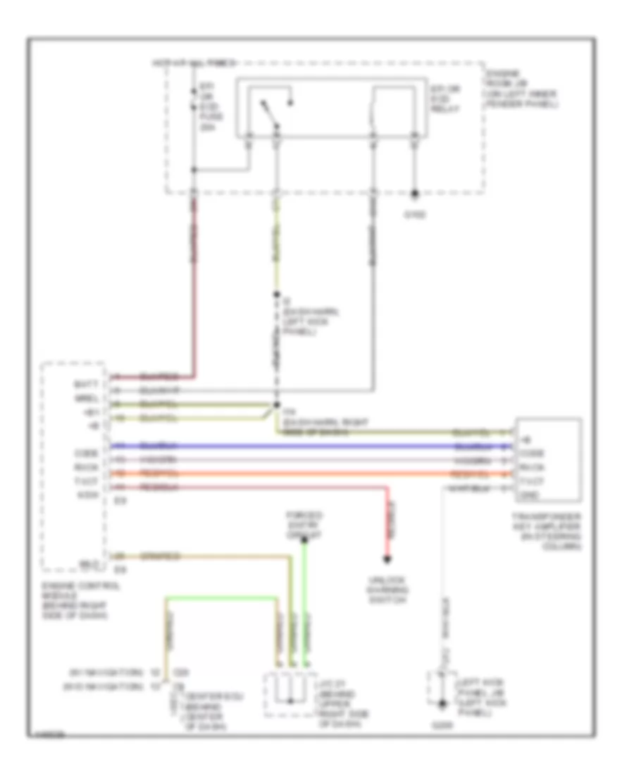
Immobilizer Wiring Diagram for Toyota Land Cruiser 2001
List of elements for Immobilizer Wiring Diagram for Toyota Land Cruiser 2001:
- (w/ navigation)
- (w/o navigation)
- +b1
- Batt
- C13
- C20
- Center ecu (behind center of dash)
- Code
- D12
- Efi or ecd fuse 20a
- Efi or ecd relay
- Engine control module (behind right side of dash)
- Engine room j/b (on left inner fender panel)
- Forced entry circuit
- G102
- G200
- Gnd
- Hot at all times
- I-sec
- I14 (dash harn, right side of dash)
- I2 (dash harn, left kick panel)
- Imld
- J/c 21 (behind upper right side of dash)
- Ksw
- Left kick panel j/b (left kick panel)
- Mrel
- Rxck
- Transponder key amplifier (in steering column)
- Txct
- Unlock warning switch
BODY COMPUTER
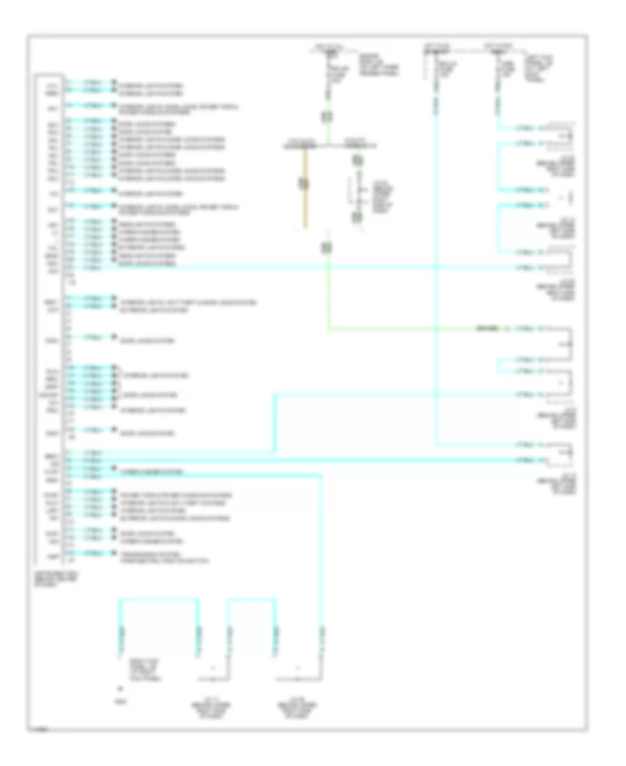
Body Computer Wiring Diagrams for Toyota Land Cruiser 2001
List of elements for Body Computer Wiring Diagrams for Toyota Land Cruiser 2001:
- A red
- Acc
- Acy
- Becu
- D(d)ury
- D10
- Dcy
- Ddry
- Disw
- Dkl
- Dku
- Dlry
- Dml
- Dmu
- Door locks system
- Door locks systems
- Ecu-b1 fuse 20a
- Ecu-ig fuse 15a
- Engine room j/b (on left inner fender panel)
- Exterior lights & door locks systems
- Exterior lights system
- Frcl
- Frrm
- G203
- Gnd1
- Head
- Headlights systems
- Hot at all times
- Hot in acc or on
- Hot in on or start
- Hry
- I19
- I20
- I21
- Indp
- Instrument ecu (behind center of dash)
- Interior lights & anti-theft systems
- Interior lights & door locks systems
- Interior lights system
- Interior lights, anti-theft & door locks system
- Interior lights, door locks, power tops & power windows systems
- J/c 10 (behind upper left side of dash)
- J/c 12 (behind upper left side of dash)
- J/c 17 (behind upper right side of dash)
- J/c 20 (behind upper right side of dash)
- J/c 28 (behind upper right side of dash)
- J/c 29 (behind upper right side of dash)
- J/c 30 (behind upper right side of dash)
- J/c 9 (behind upper left side of dash)
- Ksw
- Kyil
- Left kick panel j/b (at left kick panel)
- Lmry
- Ls/m
- Mirr fuse 15a
- P25
- P53
- Pcy
- Pisw
- Pkl
- Pku
- Pml
- Pmu
- Power tops & power windows systems
- Pwry
- Right kick panel j/b (at right kick panel)
- Rlcl
- Rlcy
- Rrcl
- Rrcy
- Sig
- Stp
- Tail
- Transmission system (park/neutral position switch)
- Try
- W/auto- headlights
- W/o auto- headlights
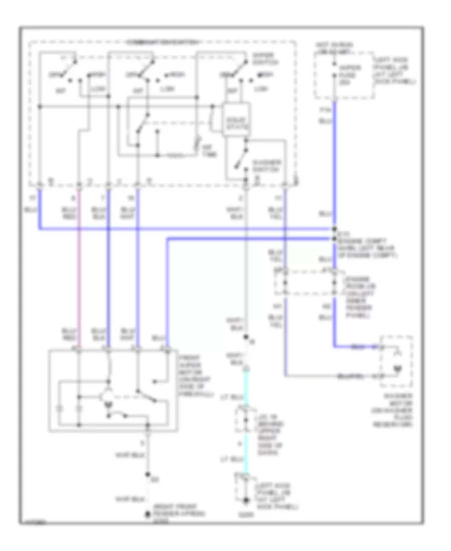
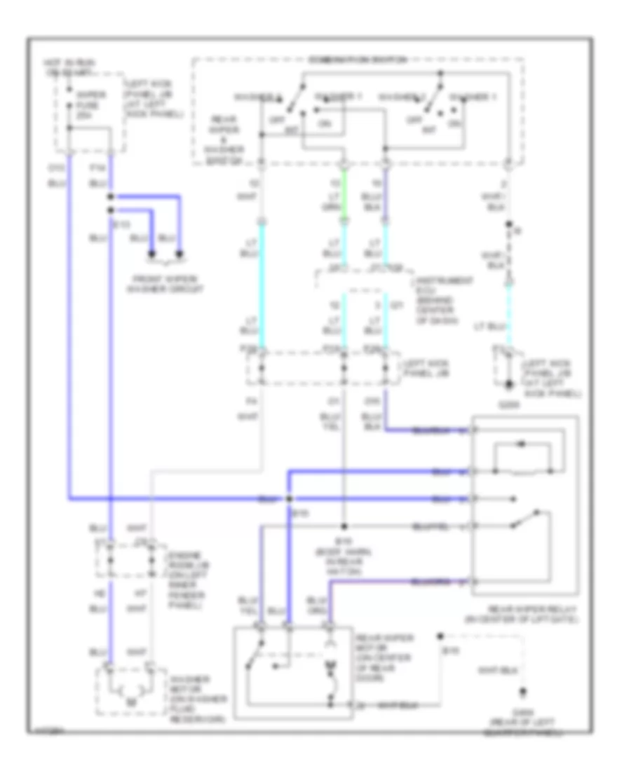
- Wiper/washer system
- Wlry
COMPUTER DATA LINES
Computer Data Lines for Toyota Land Cruiser 2001
List of elements for Computer Data Lines for Toyota Land Cruiser 2001:
- (dash harn, left side of dash)
- A21
- A23
- A42
- Abs & ba & trac & vsc ecu (behind left side of dash)
- Abs ecu (behind left side of dash)
- Abs sol relay
- B13
- B16
- Bat
- C10
- Center air bag sensor assembly (under front of center console)
- D/g
- D15
- D16
- Data link connector 1 (right side of engine compt)
- Data link connector 3 (behind left side of dash)
- E10
- Efi or ecd fuse 20a
- Efi or ecd relay
- Engine control module (behind right side of dash)
- Engine room j/b (on left inner fender panel)
- G120 (rear side of right cylinder head)
- G200
- Hot at all times
- I2 (dash harn, left end of dash)
- Instrument cluster system
- Junction connector j16 (behind upper right side of dash)
- Junction connector j21 (behind upper right side of dash)
- Junction connector j7 (behind upper center of dash)
- Left kick panel j/b (at left kick panel)
- Multi- display
- Obd fuse 10a
- Pnk/pnk
- Sil
- W/o vsc
- W/vsc
- Wfse
COOLING FAN
Cooling Fan Wiring Diagram for Toyota Land Cruiser 2001
List of elements for Cooling Fan Wiring Diagram for Toyota Land Cruiser 2001:
- (front right side of fender apron) g101
- (front right side of fender apron) g103
- A/c amplifier (center ecu) (behind center of dash)
- A/c condenser fan motor (on right front of eng compt)
- A/c condenser fan relay (on left front of engine compartment, near headlight)
- A/c fuse 20a
- A/c magnetic clutch & lock sensor (on a/c compressor)
- A/c triple pressure switch (left front of engine compartment, near headlight assembly)
- B14
- C14
- Cds fan fuse 20a
- E19
- Engine room j/b (on left inner fender panel)
- Hot at all times
- Hot in on or start
- L13
- L14
- L17
- L19
- Left kick panel j/b (at left kick panel)
- Mg clt relay
- Mgc
- Single
CRUISE CONTROL
Cruise Control Wiring Diagram for Toyota Land Cruiser 2001
List of elements for Cruise Control Wiring Diagram for Toyota Land Cruiser 2001:
- (behind left side of dash, right of steering column) data link connector 3
- (dash harn, left side of dash)
- (dash harn, right side of dash) i14
- (on right side of engine compt) data link connector 1
- (transmission) (on left side of transmission)
- +b1
- +bm
- A/t indicator light switch (park/neutral position switch)
- Accel position sensor (on top front of engine)
- B nca
- B10
- Bat
- Batt
- C12
- C13
- Cancel
- Ccs
- Cl+
- Cl-
- Combination meter
- Combination switch
- Cruise
- Cruise control switch
- Cruise ind
- D21
- E01
- E02
- E03
- E10
- E10 (engine harn, rear of engine)
- Efi or ecd fuse 20a
- Efi or ecd relay
- Engine control module (behind right side of dash)
- Engine room j/b (on left inner fender panel)
- Eom
- G102
- G120 (rear of right cyl head)
- G200
- Gauge fuse 15a
- Ge01
- Hot at all times
- Hot in run or start
- I2 (dash harn, left kick panel)
- Ign fuse 10a
- Igsw
- J/c 14 (behind upper center of dash)
- J/c 16 (behind upper right side of dash)
- J/c 17 (behind upper right side of dash)
- J/c 18 (behind upper right side of dash)
- J/c 20 (behind upper right side of dash)
- J/c 21 (behind upper right side of dash)
- J/c 25 (behind glove box)
- J/c 43
- J/c 43 (behind upper left side of dash)
- J/c 7 (behind upper center of dash)
- Left kick panel j/b
- Left kick panel j/b (at left kick panel)
- Me01
- Mrel
- Obd fuse 10a
- P38
- P49
- P56
- P83
- Red
- Res/ acc
- Set/ coast
- Sil
- Sp2+
- Sp2-
- Spd
- Speedo- meter
- St-
- Stop fuse 15a
- Stoplight switch (on bracket, above brake pedal)
- Stp
- Throttle control motor (on top left front of engine)
- Throttle fuse 15a
- Throttle position sensor (on throttle body assembly)
- Vehicle speed sensor
- Vehicle speed sensor (combination meter) (on left side of transmission)
- Vpa
- Vpa2
- Vta
- Vta2
DEFOGGERS
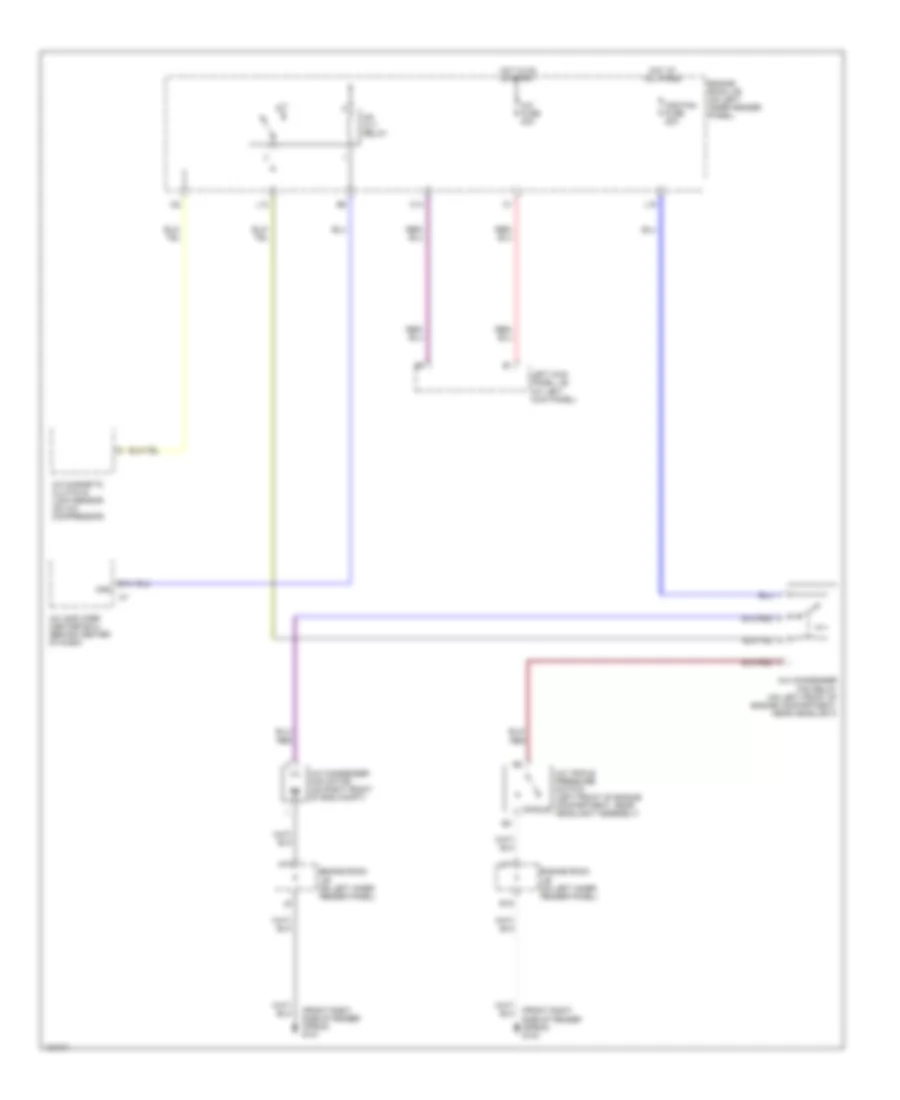
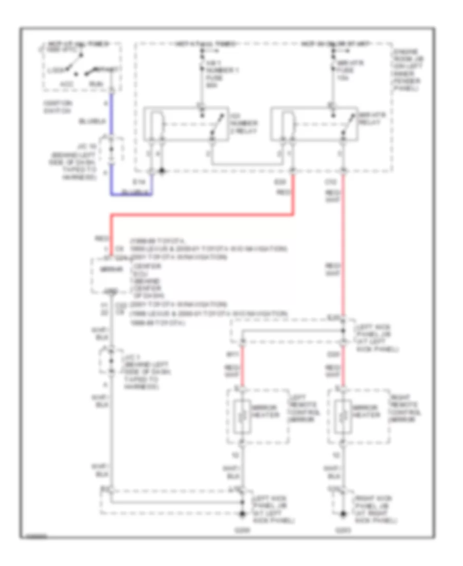
Heated Mirrors Wiring Diagram for Toyota Land Cruiser 2001
List of elements for Heated Mirrors Wiring Diagram for Toyota Land Cruiser 2001:
- (1998 lexus & 2000-01 toyota w/o navigation,
- (1998-99 toyota, 1998 lexus & 2000-01 toyota w/o navigation) (2001 toyota w/navigation)
- (2001 toyota w/navigation)
- (behind left side of dash, taped to harness)
- 1998-99 toyota)
- Acc
- Am 1 number 1 fuse 80a
- C12
- C22
- C24
- Center ecu (behind center of dash)
- D20
- E10
- E14
- E20
- Engine room j/b (on left inner fender panel)
- G10
- G200
- G203
- Grd
- Hot at all times
- Hot at all times 1995 vftc
- Hot in on or start
- Ig1 number 2 relay
- Ignition switch
- J/c 1 (behind left side of dash, taped to harness)
- J/c 10
- L10
- Left kick panel j/b (at left kick panel)
- Left remote control mirror
- Lock
- M11
- Mir htr fuse 15a
- Mir htr relay
- Mirror heater
- Mrrhr
- Red
- Right kick panel j/b (at right kick panel)
- Right remote control mirror
- Run
- Start
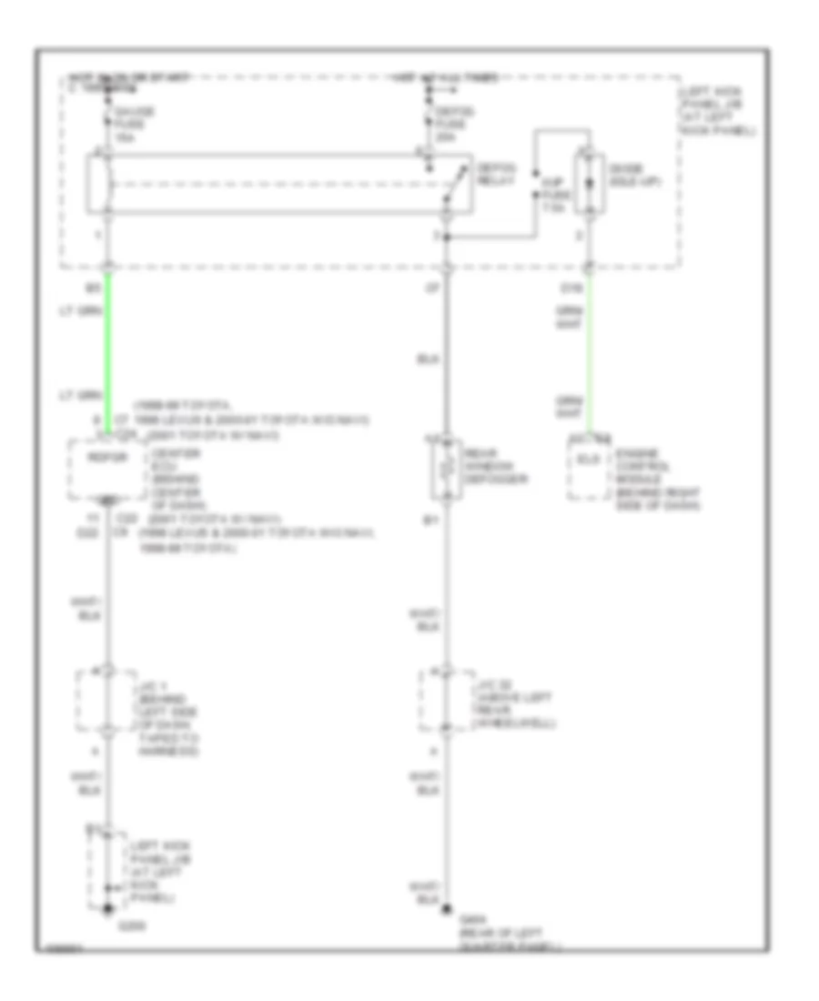
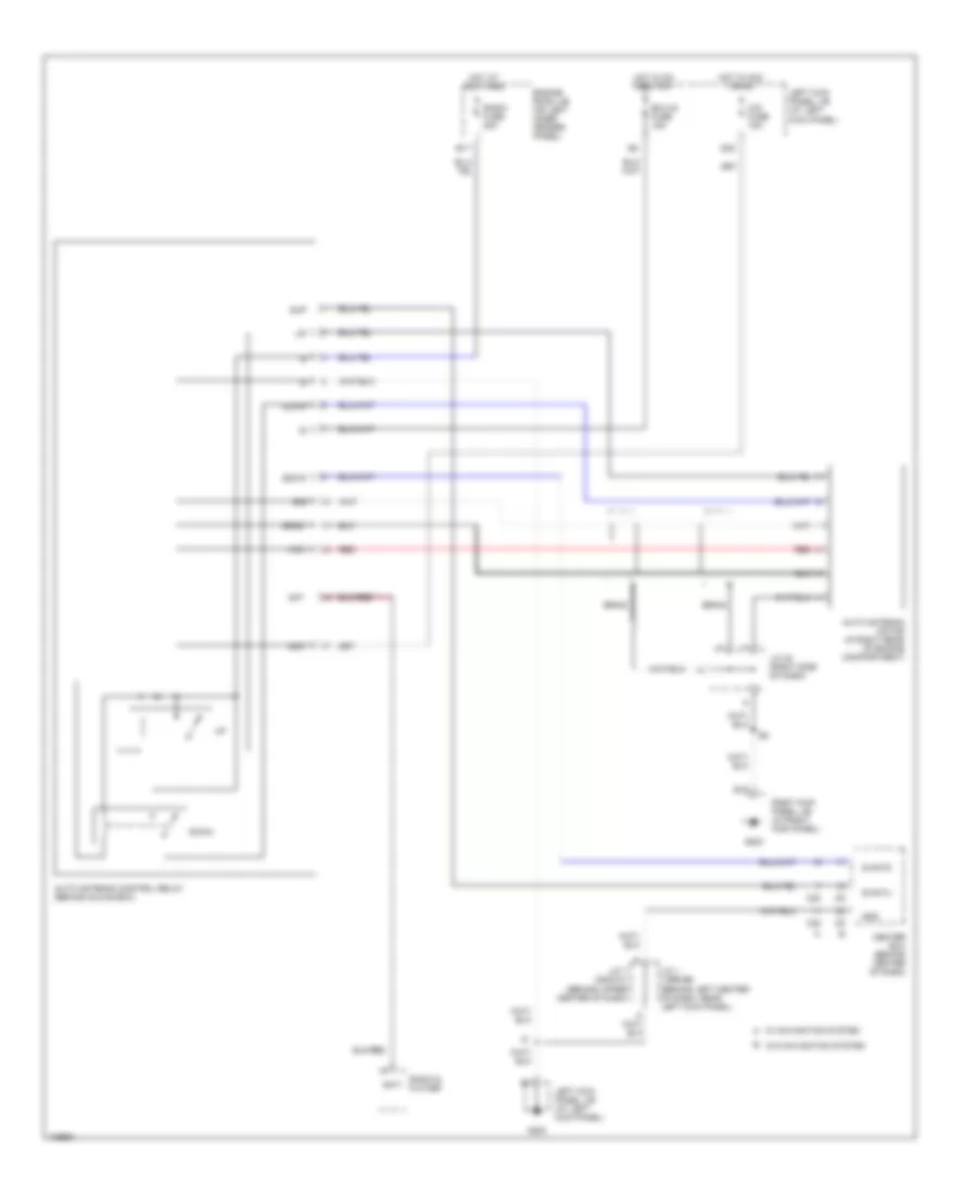
Rear Defogger Wiring Diagram for Toyota Land Cruiser 2001
List of elements for Rear Defogger Wiring Diagram for Toyota Land Cruiser 2001:
- (1998 lexus & 2000-01 toyota w/o navi,
- (1998-99 toyota,
- (2001 toyota w/ navi)
- (rear of left quarter panel)
- 1998 lexus & 2000-01 toyota w/o navi)
- 1998-99 toyota)
- C 1995 vftc
- C22
- C24
- Center ecu (behind center of dash)
- D18
- D22
- Defog fuse 20a
- Defog relay
- Diode (idle-up)
- Els
- Engine control module (behind right side of dash)
- G200
- G404
- Gauge fuse 15a
- Grd
- Hot at all times
- Hot in on or start
- I/up fuse 7.5a
- J/c 1 (behind left side of dash, taped to harness)
- J/c 32 (above left rear wheelwell)
- Left kick panel j/b (at left kick panel)
- Rdfgr
- Rear window defogger
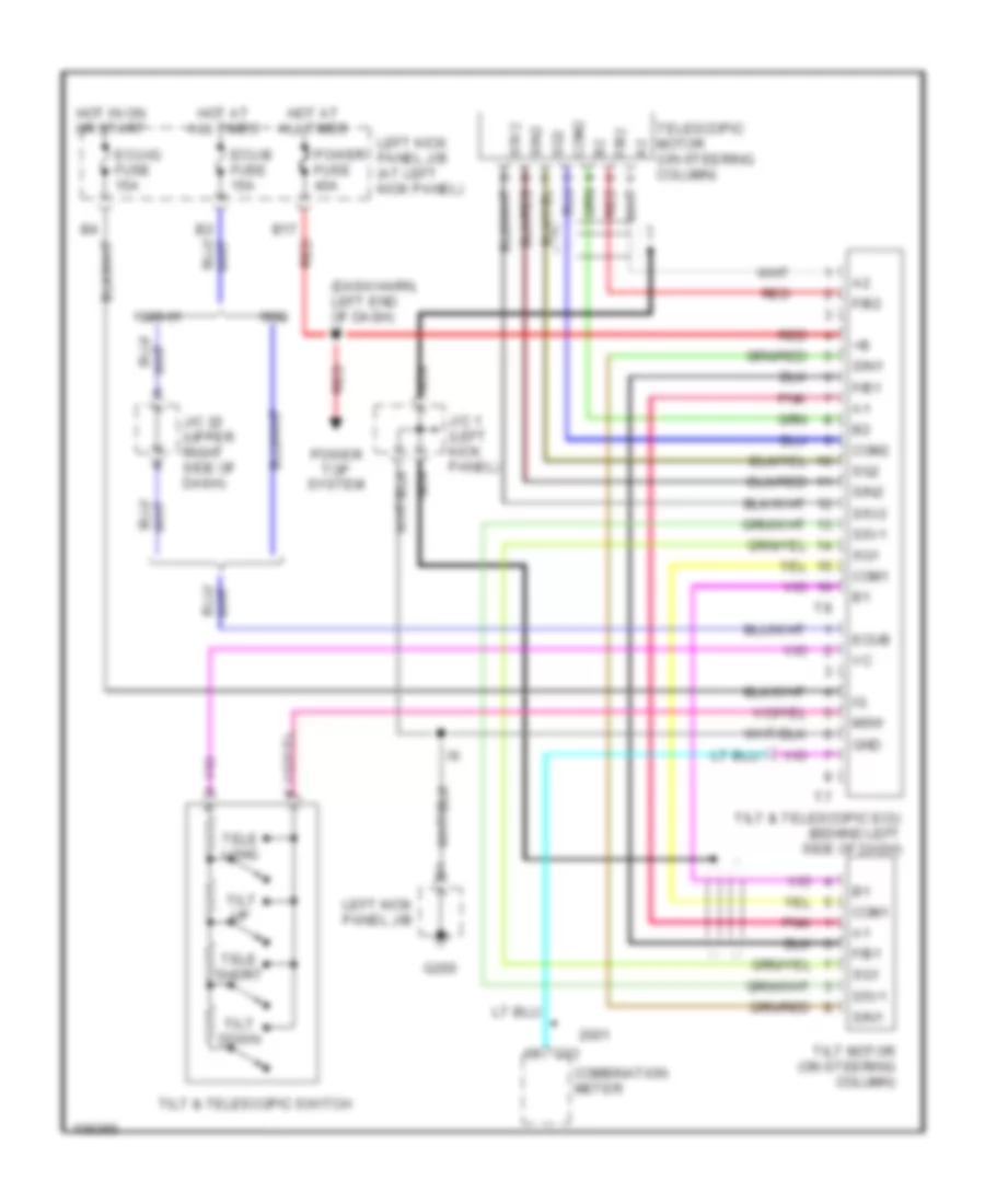
ELECTRONIC POWER STEERING
Power Steering Column Wiring Diagram for Toyota Land Cruiser 2001
List of elements for Power Steering Column Wiring Diagram for Toyota Land Cruiser 2001:
- (dash harn, left end of dash) i1
- 1999-01
- B17 red
- C13
- Com1
- Com2
- Combination meter
- Ecu-b fuse 15a
- Ecu-ig fuse 15a
- Ecub
- F/b1
- F/b2
- G200
- Gnd
- Hot at all times
- Hot in on or start
- J/c 1 (left kick panel)
- J/c 22 (upper right side of dash)
- Left kick panel j/b
- Left kick panel j/b (at left kick panel)
- Msw
- Nca
- Pnk
- Power fuse 40a
- Power top system
- Red
- S5v1
- S5v2
- Sg1
- Sg2
- Sin1
- Sin2
- Tele long
- Tele short
- Telescopic motor (on steering column)
- Tilt & telescopic ecu (behind left side of dash)
- Tilt & telescopic switch
- Tilt down
- Tilt motor (on steering column)
- Tilt up
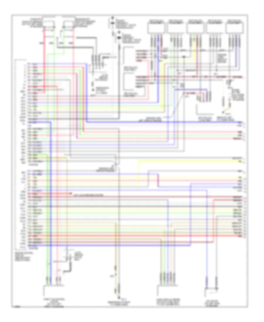
ENGINE PERFORMANCE
4.7L
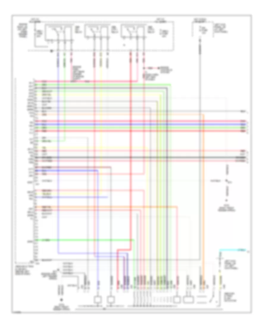
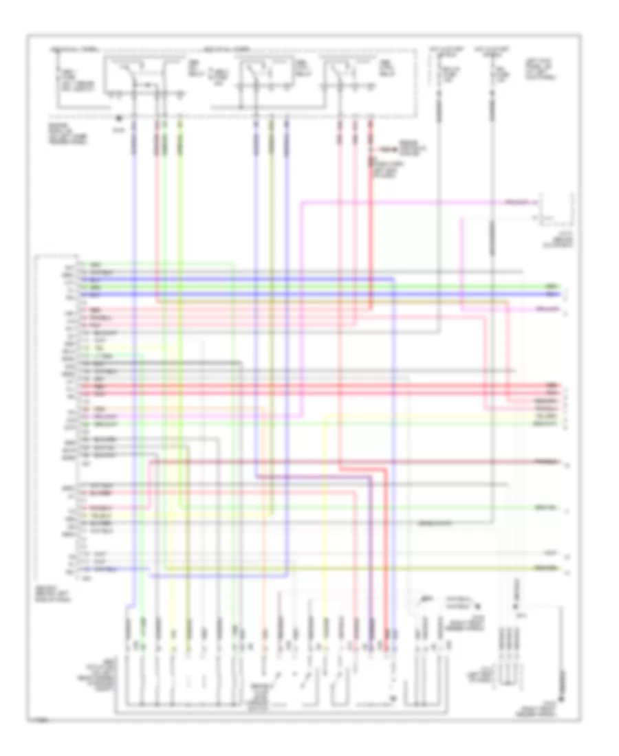
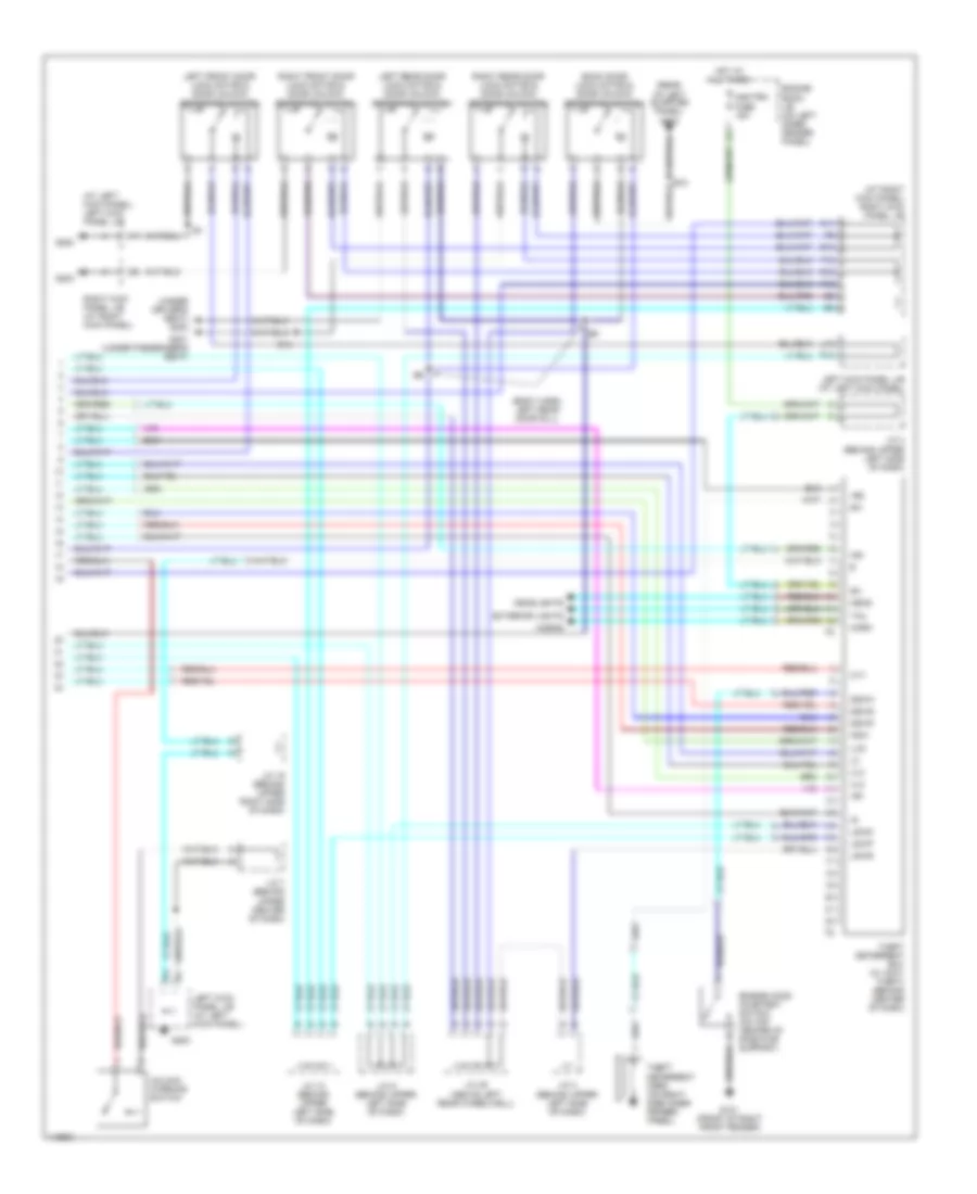
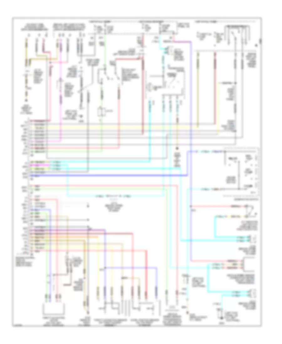
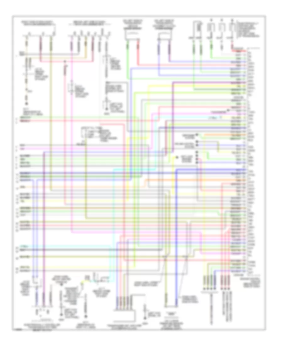
4.7L, Engine Performance Wiring Diagrams (1 of 4) for Toyota Land Cruiser 2001
List of elements for 4.7L, Engine Performance Wiring Diagrams (1 of 4) for Toyota Land Cruiser 2001:
- (engine harn, left side of engine)
- (engine harn, rear of engine)
- (rear bank of right cyl head)
- (rear bank of right cylinder head)
- (rear of left cylinder head)
- Anti-lock brakes system
- B braided
- Braid
- Braid a
- Camshaft position sensor (on top left side of engine)
- Cl+
- Cl-
- Conn e5
- Conn e6
- Crankshaft position sensor (on left front of engine)
- E01
- E02
- E03
- E10
- E11
- E7 (engine harn, rear of engine)
- Els4
- Engine control module (behind right side of dash)
- Evg
- G114
- G117
- Ge01
- Htl
- Htl2
- Htr
- Htr2
- Igf1
- Igf2
- Ignition coil & igniter 1
- Ignition coil & igniter 2
- Ignition coil & igniter 3
- Ignition coil & igniter 4
- Ignition coil & igniter 5
- Ignition coil & igniter 6
- Ignition coil & igniter 7
- Ignition coil & igniter 8
- Igt1
- Igt2
- Igt3
- Igt4
- Igt5
- Igt6
- Igt7
- Igt8
- J/c 25 (behind glove box)
- Knkl
- Knkr
- Knock sensor 1 (on left top of engine block)
- Knock sensor 2 (on right top of engine block)
- Mass airflow meter (on air intake, next to air cleaner box)
- Me01
- Ne+
- Ne-
- Noise filter (on upper left side of engine)
- Oxl1
- Oxl2
- Oxr1
- Oxr2
- Prg
- Red
- Tha
- Throttle control motor (on top left front of engine)
- Thw
- Vpa
- Vpa2
- Vsv (evap) (on left side of engine)
- Vta
- Vta2
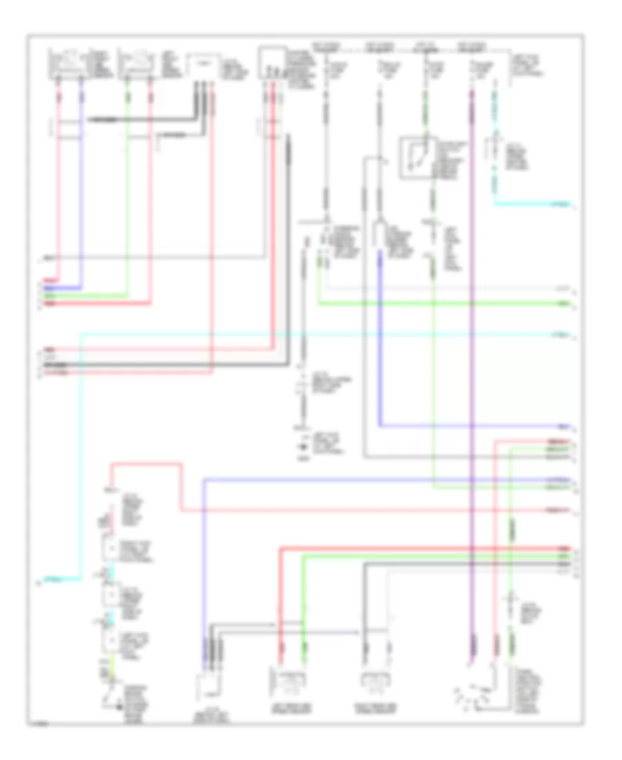
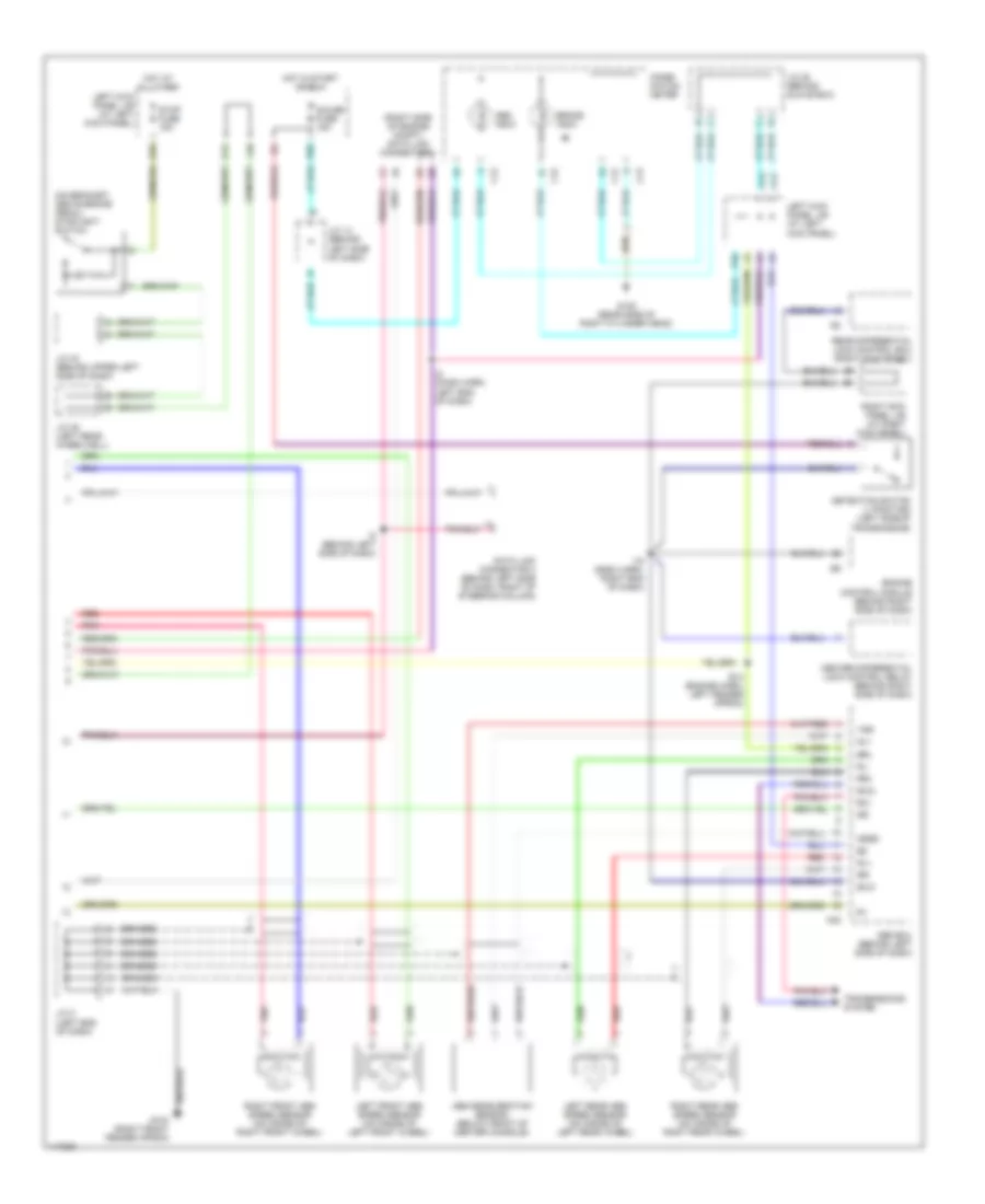
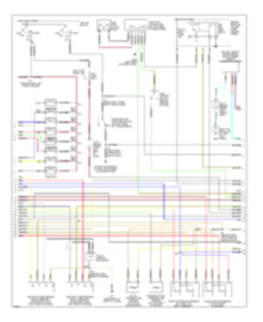
4.7L, Engine Performance Wiring Diagrams (2 of 4) for Toyota Land Cruiser 2001
List of elements for 4.7L, Engine Performance Wiring Diagrams (2 of 4) for Toyota Land Cruiser 2001:
- (dash harn, upper right end of dash)
- (engine harn, left side of engine)
- (on left side of transmission) vehicle speed sensor (combination meter)
- A/t oil temperature sensor (on top of transmission)
- Acc
- Accel position sensor (on top front of engine)
- Am2
- B12
- Braid
- C13
- D13
- D21
- E10
- E10 (engine harn, rear of engine)
- E11
- E4 (engine harn, right rear of engine compt)
- Efi or ecd fuse 20a
- Efi or ecd relay
- Engine coolant temperature sensor (on top front of engine)
- Engine room j/b (on left inner fender panel)
- Fp+
- Fp-
- Fpc
- Fuel control switch (behind center of dash)
- Fuel pump (in fuel tank)
- Fuel pump control ecu (on left rear of cargo area)
- G117 (rear bank of right cyl head)
- G200
- G404 (left rear quarter panel)
- Heated oxygen sensor (bank 1 sensor 1) (on exhaust pipe, left rear of engine)
- Heated oxygen sensor (bank 2 sensor 1) (on exhaust pipe, right side of engine)
- Hot at all times
- Ig2
- Ign fuse 10a
- Ignition switch
- Injector 1
- Injector 2
- Injector 3
- Injector 4
- Injector 5
- Injector 6
- Injector 7
- Injector 8
- J/c 17 (behind upper right side of dash)
- J/c 24 (behind glove box)
- J/c 43 (behind upper left side of dash)
- Left kick panel j/b
- Left kick panel j/b (at left kick panel)
- Lock
- P/n
- P56
- Park/neutral position switch (on left side of transmission)
- Red
- Right side of dash)
- Start
- Starting/charging system, instrument cluster system
- Throttle position sensor (on throttle body assembly)
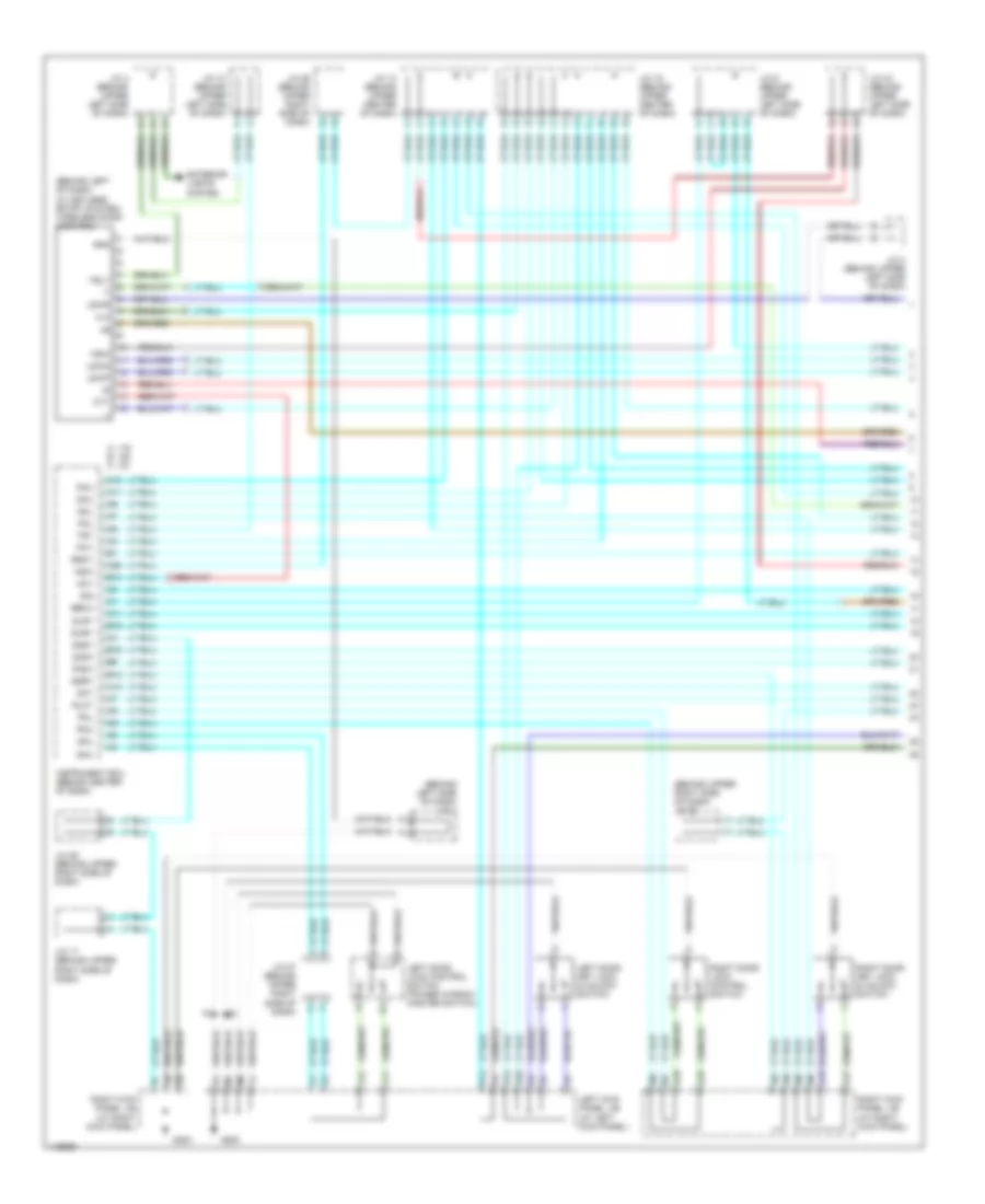
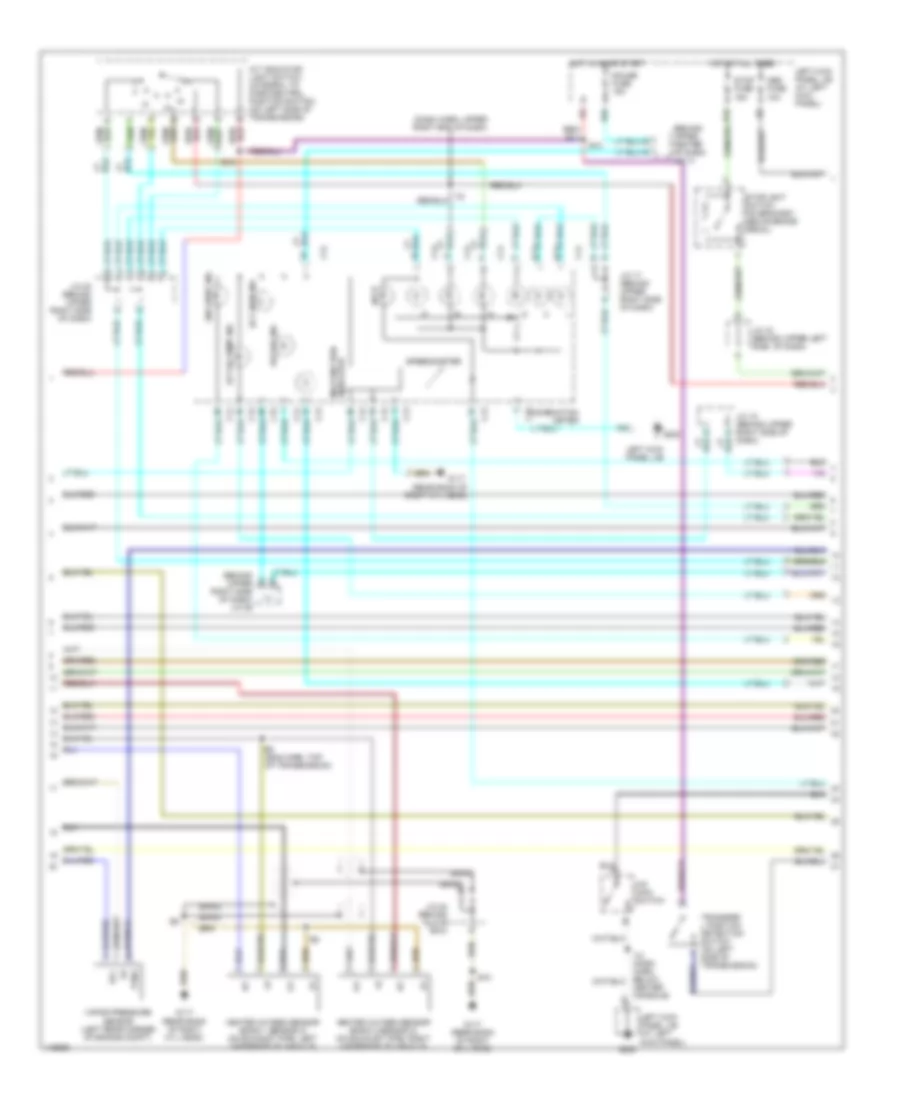
4.7L, Engine Performance Wiring Diagrams (3 of 4) for Toyota Land Cruiser 2001
List of elements for 4.7L, Engine Performance Wiring Diagrams (3 of 4) for Toyota Land Cruiser 2001:
- (behind upper center of dash) j/c 14
- (behind upper g
- (dash harn, upper right end of dash)
- (eng harn, top of transmission)
- (rear bank of right cyl head)
- 2nd strt ind
- A/t indicator light switch (integral to park/neutral position switch) (on left side of transmission)
- A/t oil temp ind
- A/t p
- B10
- Braid
- C12
- C13
- C14
- C15
- Center console)
- Combination meter
- E10
- Ect pwr ind
- G117
- G117 (rear bank of right cyl head)
- G200
- Gauge fuse 15a
- Heated oxygen sensor (bank 1 sensor 2) (on exhaust pipe, left underside of vehicle)
- Heated oxygen sensor (bank 2 sensor 2) (on exhaust pipe, right underside of vehicle)
- Hot at all times
- Hot in on or start
- J/c 17 (behind upper right side of dash)
- J/c 18 (behind upper right side of dash)
- J/c 20 (behind upper right side of dash)
- J/c 24 (behind glove box)
- J/c 43 (behind upper left side of dash)
- Left kick panel j/b
- Left kick panel j/b (at left kick panel)
- Malfunction indicator
- O/d main switch
- O/d off ind
- Obd fuse 10a
- P83
- Ptnk
- Right side of dash) j/c 26
- Speedometer
- Stop fuse 15a
- Stoplight switch (on bracket, above brake pedal)
- Transfer l position detection switch (on left side of transmission)
- Vapor pressure sensor (left rear corner of engine compt)
- Vcc
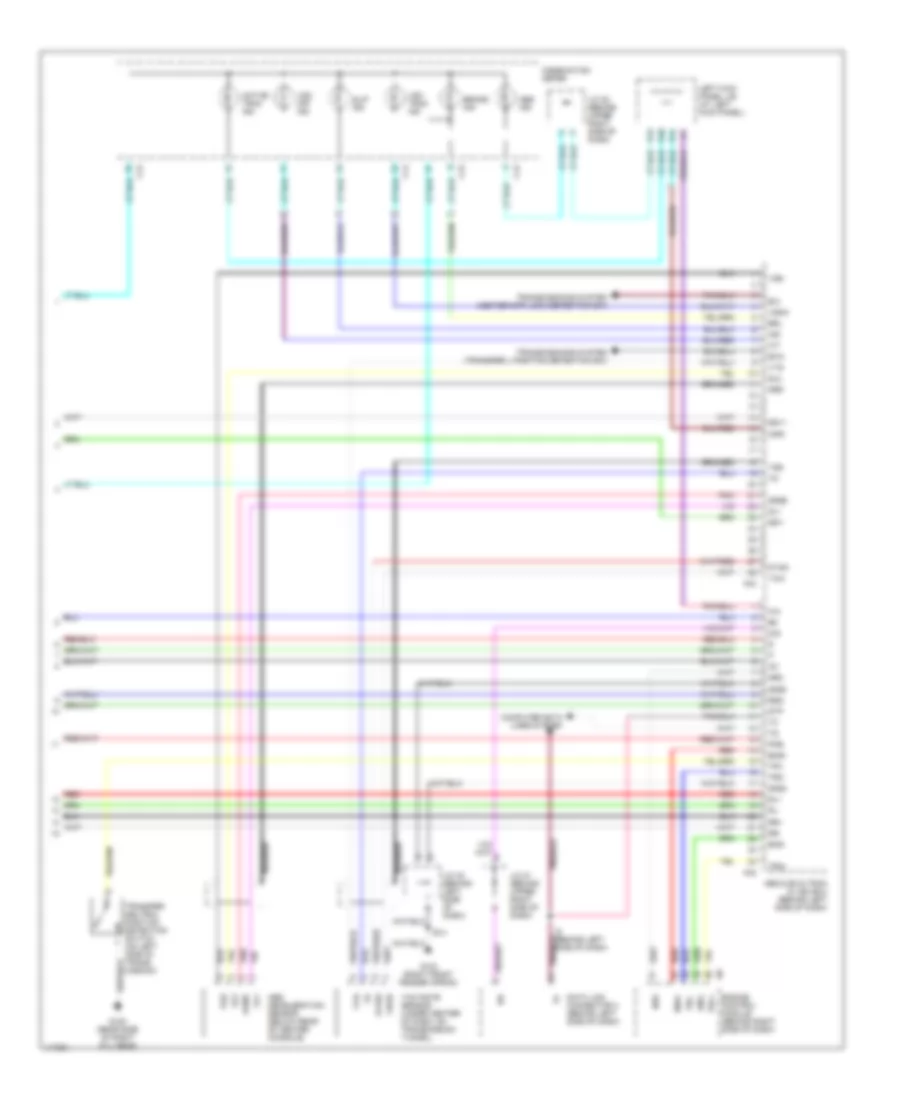
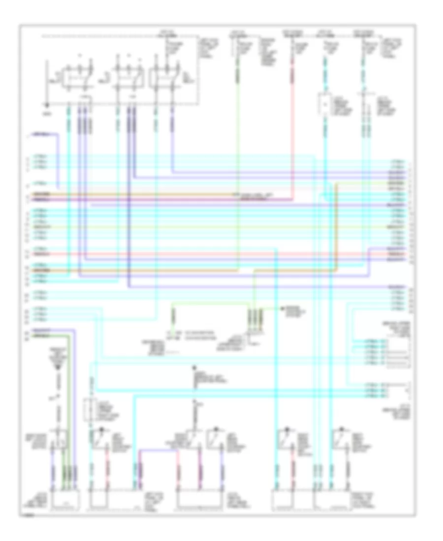
4.7L, Engine Performance Wiring Diagrams (4 of 4) for Toyota Land Cruiser 2001
List of elements for 4.7L, Engine Performance Wiring Diagrams (4 of 4) for Toyota Land Cruiser 2001:
- (behind left side of dash) data link connector 3
- (dash harn, below center console) i12
- (dash harn, upper right end of dash)
- (dash harn, upper right side of dash)
- (on left side of transmission) o/d direct clutch speed sensor
- (on left side of transmission) vehicle speed sensor
- (right side of eng compt)
- +b1
- +bm
- 2nd
- A/c
- Act
- Air conditioning system
- Anti-lock brakes system
- Anti-theft system
- Bat
- Batt
- Ccs
- Code
- Conn e7
- Conn e8
- Conn e9
- Cruise control system
- D12
- Data link connector 1
- Defogger system
- E10
- Egn-
- Electronically controlled transmission pattern select switch
- Electronically controlled transmission solenoid (on left side of transmission)
- Els
- Els2
- Eng+
- Engine control module (behind right side of dash)
- Engine room j/b (on left inner fender panel)
- Eom
- Fpc
- G117 (rear bank of right cyl head)
- G200
- Hot at all times
- I14
- Igsw
- Imld
- J/c 16 (behind upper right side of dash)
- J/c 17 (behind upper right side of dash)
- J/c 21 (behind upper right side of dash)
- J/c 22 (behind upper right side of dash)
- J/c 7 (behind upper center of dash)
- Ksw
- Left kick panel j/b
- Left kick panel j/b (at left kick panel)
- Mrel
- Nco+
- Nco-
- Neo
- Nsw
- Odlp
- Odms
- Oil
- Oilw
- Ptnk
- Pwr
- Red
- Rxck
- Sil
- Slt+
- Slt-
- Snwi
- Snwl
- Sp2+
- Sp2-
- Spd
- St1-
- Sta
- Stp
- Tach
- Tachometer
- Tfn
- Throttle fuse 15a
- Thwo
- Tpc
- Transfer neutral position detection switch (transfer case)
- Transponder key amplifier (in steering column)
- Trc+
- Trc-
- Txct
- Unlock warning switch
- Vsv (vapor pressure sensor) (on left rear of engine compt)
- Wfse
EXTERIOR LIGHTS
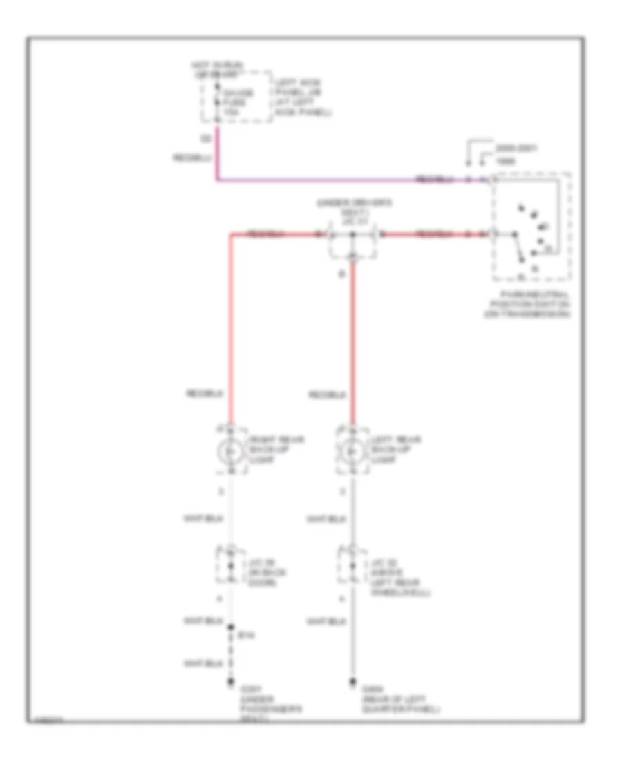
Back-up Lamps Wiring Diagram for Toyota Land Cruiser 2001
List of elements for Back-up Lamps Wiring Diagram for Toyota Land Cruiser 2001:
- (under driver's seat) j/c 31
- 2000-2001
- B14
- G301 (under passenger's seat)
- G404 (rear of left quarter panel)
- Gauge fuse 15a
- Hot in run or start
- J/c 32 (above left rear wheelwell)
- J/c 39 (in back door)
- Left kick panel j/b (at left kick panel)
- Left rear back-up light
- Park/neutral position switch (on transmission)
- Right rear back-up light
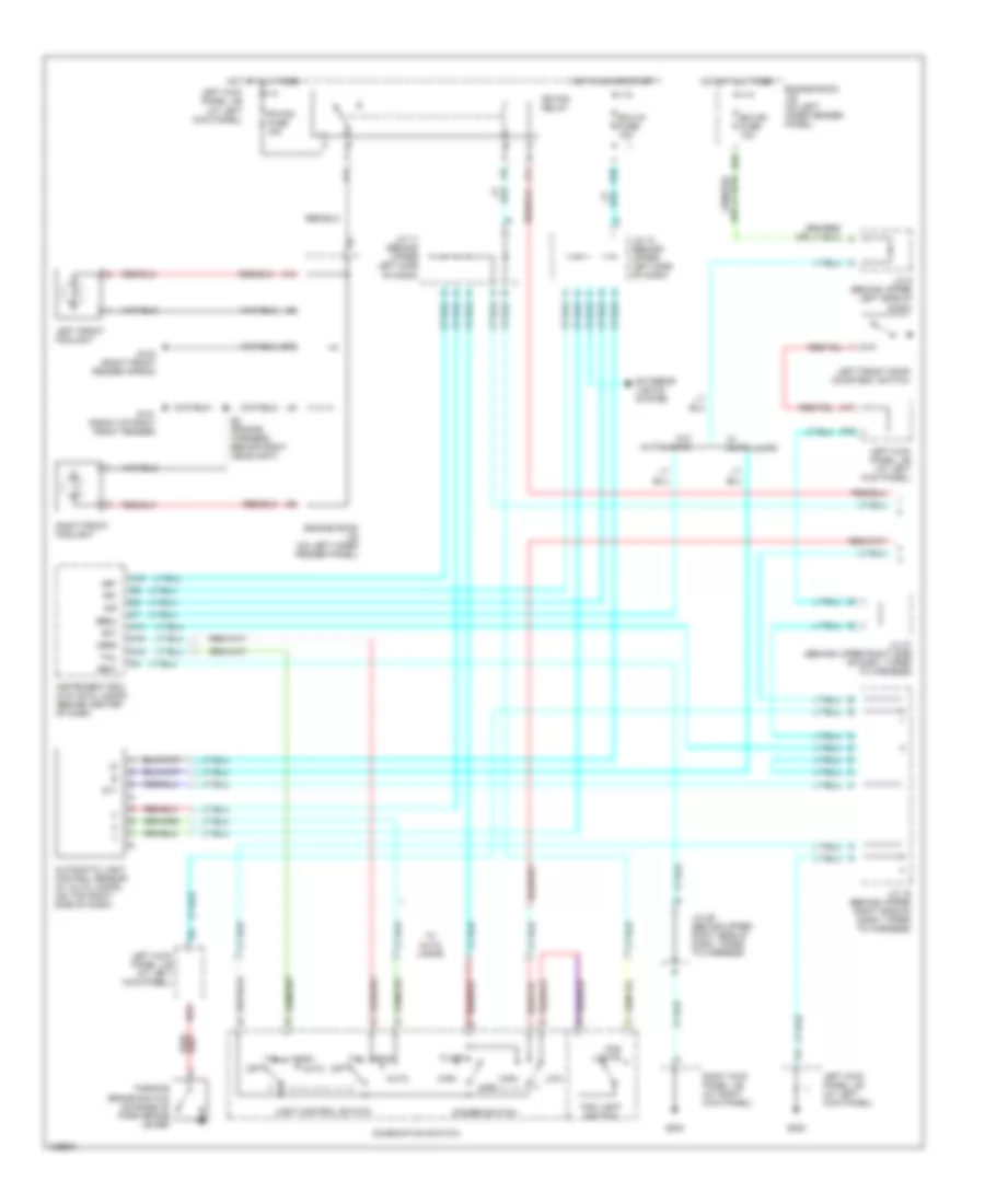
Exterior Lamps Wiring Diagram (1 of 2) for Toyota Land Cruiser 2001
List of elements for Exterior Lamps Wiring Diagram (1 of 2) for Toyota Land Cruiser 2001:
- (behind left rear wheelwell) j/c 37
- (body harn, back door lower wire) b18
- (in back door) j/c 40
- Auto
- Automatic light control sensor (on top right side of dash)
- B10
- B14
- B17
- Becu
- Cty
- D10
- Dcy
- Ecu-b1 fuse 20a
- Ecu-ig fuse 15a
- Engine room j/b (left inner fender panel)
- G200
- G301 (under passenger's seat)
- G404 (rear of left quarter panel)
- Grd1
- Head
- Headlight switch
- Headlights system
- High mounted stoplight
- Hot at all times
- Hot in start or run
- I19
- I20
- I21
- Instrument ecu (behind center of dash)
- J/c 10 (behind upper left side of dash)
- J/c 17 (behind upper right side of dash)
- J/c 19 (behind upper right side of dash)
- J/c 27 (behind upper right side of dash)
- J/c 29 (behind upper right side of dash)
- J/c 32 (above left rear wheelwell)
- J/c 35 (above left rear wheelwell)
- J/c 39 (in back door)
- J/c 43 (behind upper left side of dash)
- J/c 9 (behind upper left side of dash)
- Left front door courtesy switch
- Left kick panel j/b (at left kick panel)
- Left kick panel j/b (left kick panel)
- Left rear combination light (inner)
- Left rear combination light (outer)
- N17
- O12
- Off
- P21
- P25
- P56
- P78
- Right rear combination light (inner)
- Right rear combination light (outer)
- Sig
- Stop
- Stop fuse 15a
- Stop- light switch (on bracket, above brake pedal)
- Stp
- Tail
- Towing converter relay
- Try
- W/o rear a/c only
Exterior Lamps Wiring Diagram (2 of 2) for Toyota Land Cruiser 2001
List of elements for Exterior Lamps Wiring Diagram (2 of 2) for Toyota Land Cruiser 2001:
- (behind upper right side of dash) j/c 26
- (body harn, under cargo area floor)
- (canada)
- (combination switch) turn signal light switch
- (on left inner fender panel) engine room j/b
- (rear of left quarter panel) g404
- (under passenger seat) g301
- Acc
- Am1 number 2 fuse 20a
- Anti- theft, door locks systems
- B11
- B14
- B15
- B17
- B18 (body harn, back door lower wire)
- C20
- C22
- Combination meter
- E12
- E15
- E5 (engine harn, right fender apron)
- Engine room j/b (on left inner fender panel)
- F13
- G101 (front of right front fender)
- G103 (right front fender apron)
- G200
- Haz-trn fuse 15a
- Hazard switch
- Hot at all times
- I10
- I83
- Ignition switch
- J/c 1 (behind left side of dash)
- J/c 14 (behind upper center of dash)
- J/c 19 (behind upper right side of dash)
- J/c 3 (behind upper left side of dash)
- J/c 33 (above left rear wheelwell)
- J/c 34 (above left rear wheelwell)
- J/c 37 (behind left rear wheelwell)
- J/c 38, 40 (in back door)
- J/c 4 (behind upper left side of dash)
- J/c 40 (in back door)
- J/c 7 (behind upper center of dash)
- Left
- Left & right rear combination lights (inner)
- Left front turn signal light
- Left kick panel j/b (at left kick panel)
- Left kick panel j/b (left kick panel)
- Left license plate light
- Left parking & side marker light
- Left rear combination light (outer)
- Left turn indic
- Lock
- O10
- P84
- Right
- Right front turn signal light
- Right kick panel j/b (at right kick panel)
- Right license plate light
- Right parking & side marker light
- Right rear combination light (outer)
- Right turn indic
- Run
- Start
- Tail
- Tail fuse 15a
- Tail indic (canada)
- Tail relay
- Tail▮
- Towing converter relay (left rear of cargo area)
- Turn
- Turn signal flasher (behind left side of dash)
- W/ rear a/c
- W/o navigation
- W/o rear a/c
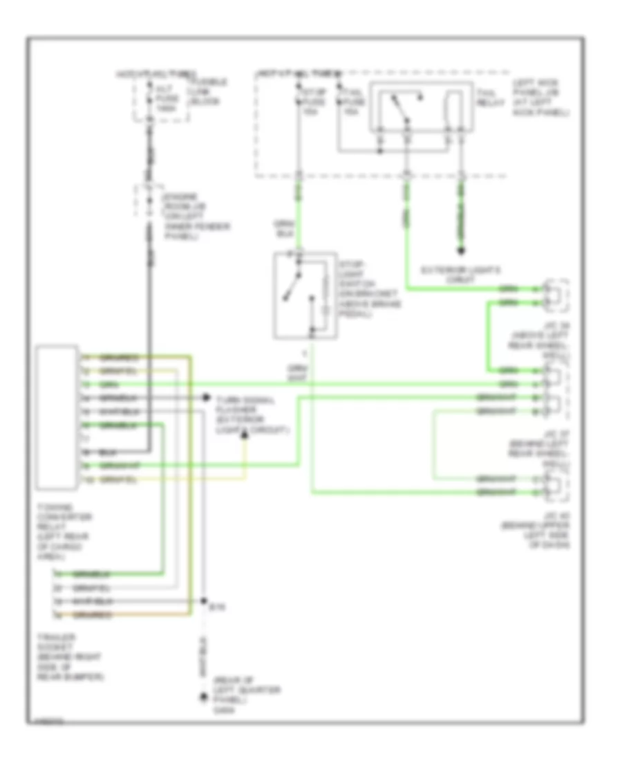
Trailer Tow Wiring Diagram for Toyota Land Cruiser 2001
List of elements for Trailer Tow Wiring Diagram for Toyota Land Cruiser 2001:
- (rear of left quarter panel) g404
- Alt fuse 140a
- B10
- B16
- C11
- Engine room j/b (on left inner fender panel)
- Exterior lights ciruit
- Fusible link block
- Hot at all times
- J/c 34 (above left rear wheel- well)
- J/c 37 (behind left rear wheel- well)
- J/c 43 (behind upper left side of dash)
- Left kick panel j/b (at left kick panel)
- O10
- Stop fuse 15a
- Stop- light switch (on bracket above brake pedal)
- Tail fuse 15a
- Tail relay
- Towing converter relay (left rear of cargo area)
- Trailer socket (behind right side of rear bumper)
- Turn signal flasher (exterior lights circuit)
GROUND DISTRIBUTION
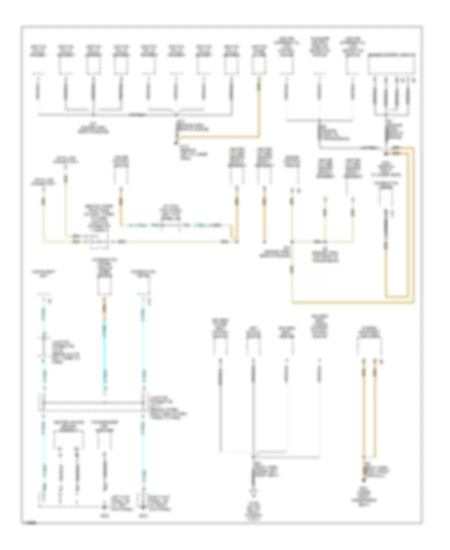
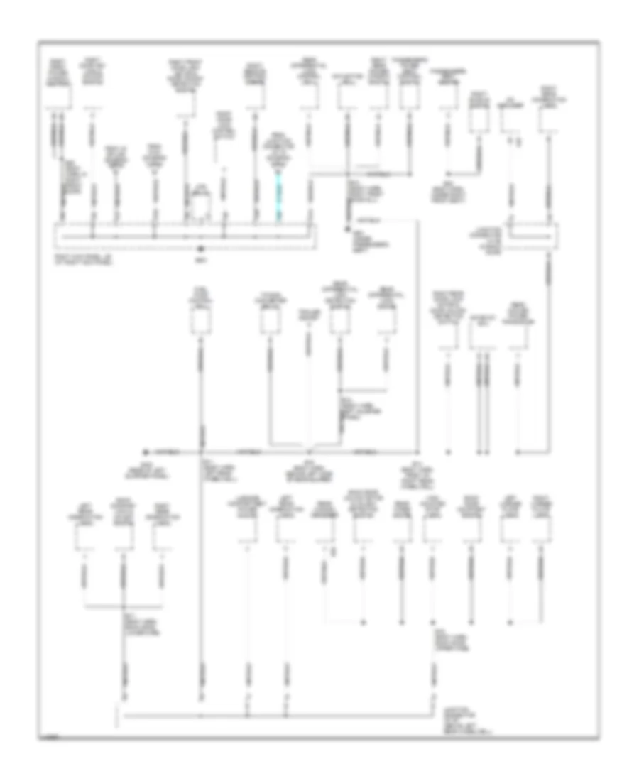
Ground Distribution Wiring Diagram (1 of 4) for Toyota Land Cruiser 2001
List of elements for Ground Distribution Wiring Diagram (1 of 4) for Toyota Land Cruiser 2001:
- (at kick kick panel) left kick panel j/b
- (behind upper right side of dash, taped to harn) junction connector j/c 16
- (combination meter) vehicle speed sensor
- B21 (body harn, under left front seat)
- C13
- Center air bag sensor assembly
- Center differential lock control motor
- Center differential lock detection switch
- Combination meter
- Cruise control switch
- D12
- Data link connector 1
- Data link connector 3
- Driver's power seat control switch
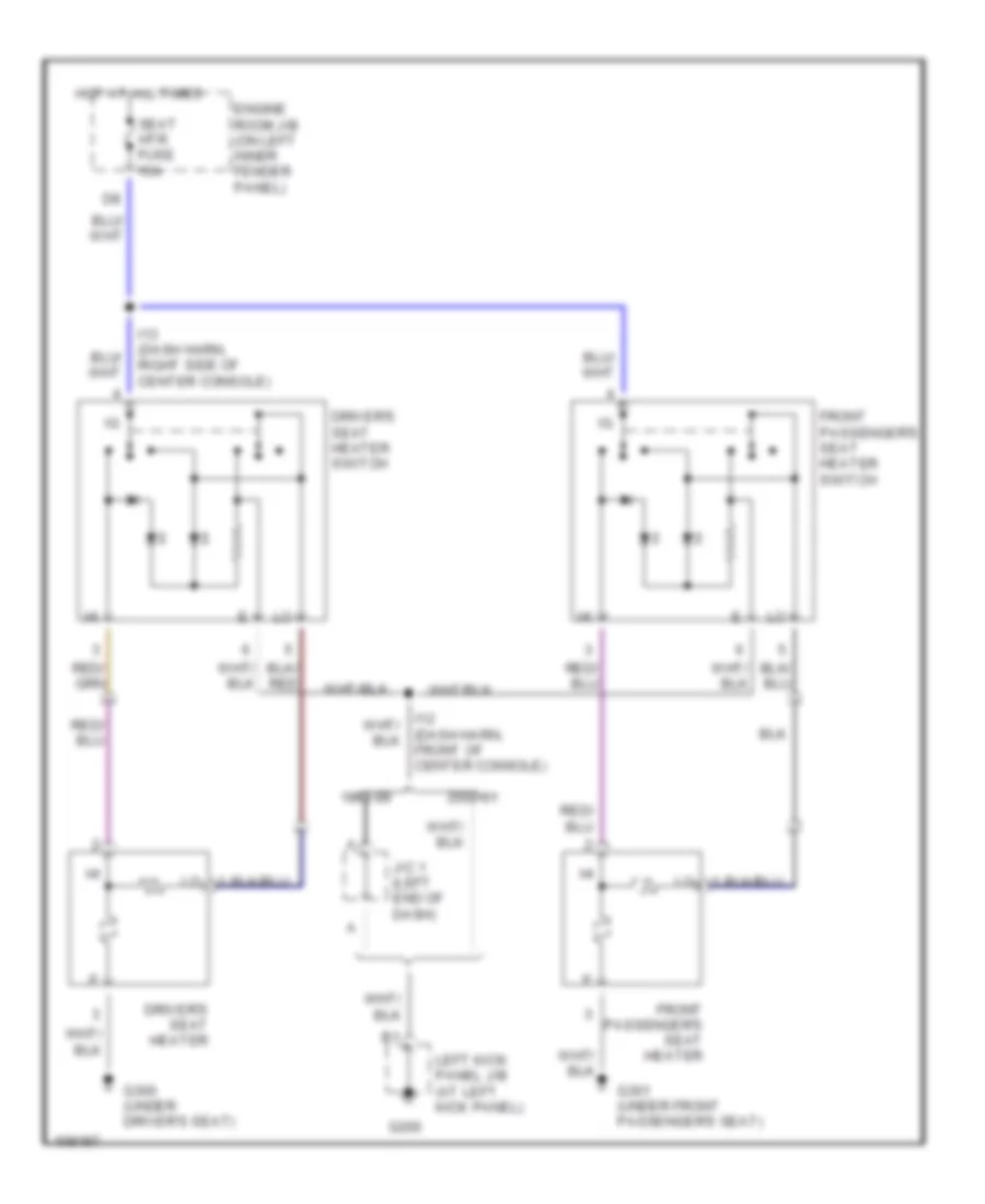
- Driver's seat heater
- Driver's seat lumbar support control switch
- E10 (engine harn, rear of engine)
- E7 (engine harn, rear of engine)
- E8 (engine harn, top front of transmission)
- E9 (engine harn, on transmission)
- Engine control module
- G112 (rear of left cylinder head)
- G120 (rear of right cylinder head)
- G200
- G203
- G301 (under front passenger's seat)
- Heated oxygen sensor (bank 1, sensor 1)
- Heated oxygen sensor (bank 1, sensor 2)
- Heated oxygen sensor (bank 2, sensor 1)
- Heated oxygen sensor (bank 2, sensor 2)
- I21
- Ignition coil & igniter 1
- Ignition coil & igniter 2
- Ignition coil & igniter 3
- Ignition coil & igniter 4
- Ignition coil & igniter 5
- Ignition coil & igniter 6
- Ignition coil & igniter 7
- Ignition coil & igniter 8
- Ignition noise filter
- Instrument ecu
- Junction connector j/c 17 (behind upper right side of dash, taped to harn)
- Junction connector j/c 29 (behind glove box, taped to harn)
- Left buckle switch
- Left kick panel j/b (at left kick panel)
- P38
- P49
- P56
- Right kick panel j/b (at right kick panel)
- Stereo component amplifier
- To b4 splice relay (diagram 3 of 4)
- Transfer neutral position detection switch
- Transponder key amplifier
Ground Distribution Wiring Diagram (2 of 4) for Toyota Land Cruiser 2001
List of elements for Ground Distribution Wiring Diagram (2 of 4) for Toyota Land Cruiser 2001:
- (rear console box) power outlet
- (w/ rear a/c)
- (w/o rear a/c)
- A/c condenser fan motor
- A/c dual pressure switch
- A/c triple switch
- Abs sol relay
- Acc relay
- Air vent mode control servo motor
- Auto antenna control relay
- Blower motor controller
- C10
- C20
- C22
- Center differential lock control relay
- Center ecu
- Cigarette lighter
- Data link connector 3
- Daytime running light relay 3
- Dvd automatic changer
- E19
- E2 (engine harn, behind right headlight)
- Efi or ecd relay
- Engine control module
- Engine hood courtesy switch
- Engine room j/b (on left front fender apron)
- Engine room j/b (on left inner fender panel)
- Front power outlet
- G101 (front of right front fender)
- G102
- I10 (dash harn, behind center of dash)
- I5 (dash harn, behind left side of dash)
- I6 (dash harn, behind left side of dash)
- Ignition 1 relay
- Ignition 2 relay
- Junction connector j/c 1 (behind left side of dash, near left kick panel)
- Junction connector j/c 7 (behind center of dash)
- Key interlock solenoid
- L14
- L15
- L17
- Left front fog- light
- Left front turn signal light
- Left lo beam headlight
- Left parking light & side marker light
- Main daytime running light relay
- Multi- display
- Rear heater switch
- Right front fog- light
- Right front turn signal light
- Right low beam headlight
- Right parking light & side marker light
- Starter relay
- Tilt & telescopic ecu
- To e14 splice (diagram 3 of 4)
- To i5 splice (diagram 3 of 4)
- To left kick panel j/b (diagram 3 of 4)
- To right kick panel j/b (diagram 4 of 4)
- Turn signal flasher
- Unlock warning switch
- W/ navigation
- W/o navigation
- W/o rear a/c
- Washer motor
- Wireless door lock ecu
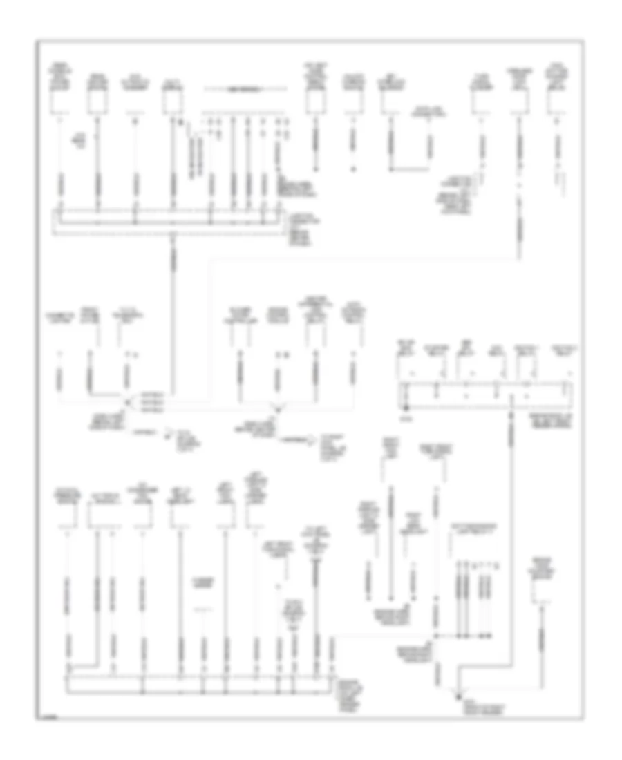
Ground Distribution Wiring Diagram (3 of 4) for Toyota Land Cruiser 2001
List of elements for Ground Distribution Wiring Diagram (3 of 4) for Toyota Land Cruiser 2001:
- (dash harn, behind left side of dash) i5
- (diagram 2 of 4)
- A b
- A10
- A11
- A21
- A23
- A37
- A38
- A40
- A41
- A42
- Abs actuator
- Abs ecu
- Auto antenna motor
- B1 (body harn, inside left front door)
- B4 (body harn, left front door sill)
- B7 (body harn, center front of roof)
- C15
- Combination meter
- Combination switch
- D/l (du) relay
- D/l (l) relay
- D/l (u) relay
- Driver's seat heater switch
- E13 (engine harn, left fender apron)
- E14 (engine harn, left fender apron)
- E5 (engine harn, right fender apron)
- Electronically controlled transmission pattern select switch
- From b21 splice (diagram 1 of 4)
- From engine room j/b (diagram 2 of 4)
- From i5 splice b
- From left kick panel j/b (diagram 3 of 4)
- Front interior light & rear personal light
- Front personal light
- Front wiper motor
- G103 (right front fender apron)
- G200
- G300 (under driver's seat)
- Glove box light
- I12 (dash harn, front of center console)
- I3 (dash harn, left side of dash)
- I9 (dash harn, behind combination meter)
- Junction connector j/c 19 (behind upper right side of dash, taped to harn)
- Junction connector j/c 2 j/c 42
- Junction connector j/c 26 (upper right side of dash)
- Junction connector j/c 30 (upper right end of dash)
- L10
- Left door key lock & unlock switch
- Left front door lock motor & door unlock detection switch
- Left kick panel j/b (at left kick panel)
- Left quarter power window switch
- Left rear door lock motor & unlock detection switch
- Left rear power window switch
- Left remote control mirror
- Left vanity light
- Moon roof control ecu
- Moon roof control switch
- O/d main switch
- O11
- P12
- Passenger's seat heater switch
- Power relay
- Power window master switch
- Rear heater blower resistor
- Rear heater fan relay
- Rear heater power transistor
- Remote control mirror switch
- Rheostat
- Right quarter power window switch
- Right vanity light
- Shift lock control ecu
- Steering angle sensor
- Theft deterrent ecu
- To left kick panel j/b (diagram 3 of 4)
- To right kick panel j/b (diagram 4 of 4)
- Turn signal light switch
- W/ abs a
- W/ vsc b
- Wiper & washer switch
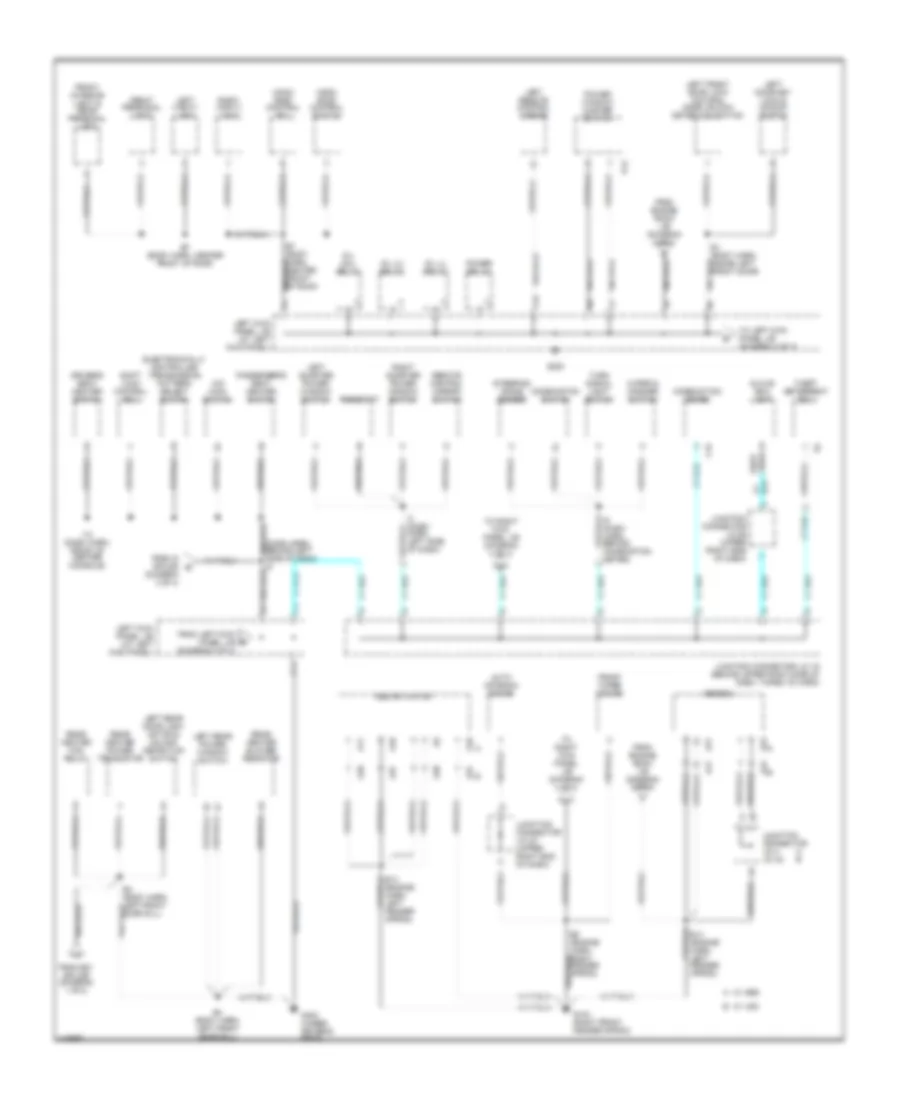
Ground Distribution Wiring Diagram (4 of 4) for Toyota Land Cruiser 2001
List of elements for Ground Distribution Wiring Diagram (4 of 4) for Toyota Land Cruiser 2001:
- A/c amplifier
- A32
- B10 (body harn, right front door sill)
- B11 (body harn, left rear wheelwell)
- B12 (body harn, left quarter panel)
- B14 (body harn, front of right rear wheelwell)
- B15 (body harn, back door upper wire)
- B16 (body harn, behind left side of rear bumper)
- B17 (body harn, back door, lower wire)
- B19
- B20 (body harn, in right front door)
- B22 (body harn, under right front seat)
- Back door courtesy switch
- Back door key lock & unlock switch
- Back door unlock motor & unlock detection switch
- E14
- From g103 (diagram 3 of 4)
- From i10 splice (diagram 3 of 4)
- From junction connector j/c 19 (diagram 3 of 4)
- Fuel pump control ecu
- G10
- G203
- G301 (under passenger's seat)
- G404 (rear of left quarter panel)
- Gateway ecu
- High mounted stop- light
- I33
- Junction connector j/c 32 (above left rear wheelwell)
- Junction connector j/c 39 (in back door)
- Left license plate light
- Left rear combination light
- Luggage compartment power outlet
- Mtr relay
- Navigation ecu
- Passenger's power seat control switch
- Passenger's seat heater
- R29
- Rear cooler power transistor
- Rear differential lock control ecu
- Rear differential lock detection switch
- Rear differential lock motor
- Rear window defogger
- Rear wiper motor
- Right buckle switch
- Right door key lock & unlock switch
- Right door lock control switch
- Right front door lock motor & door unlock detection switch
- Right front power window switch
- Right kick panel j/b (at right kick panel)
- Right license plate light
- Right rear combination light
- Right rear door lock motor & door unlock detection switch
- Right rear power window switch
- Right remote control mirror
- Towing converter relay
- Trailer socket
HEADLIGHTS
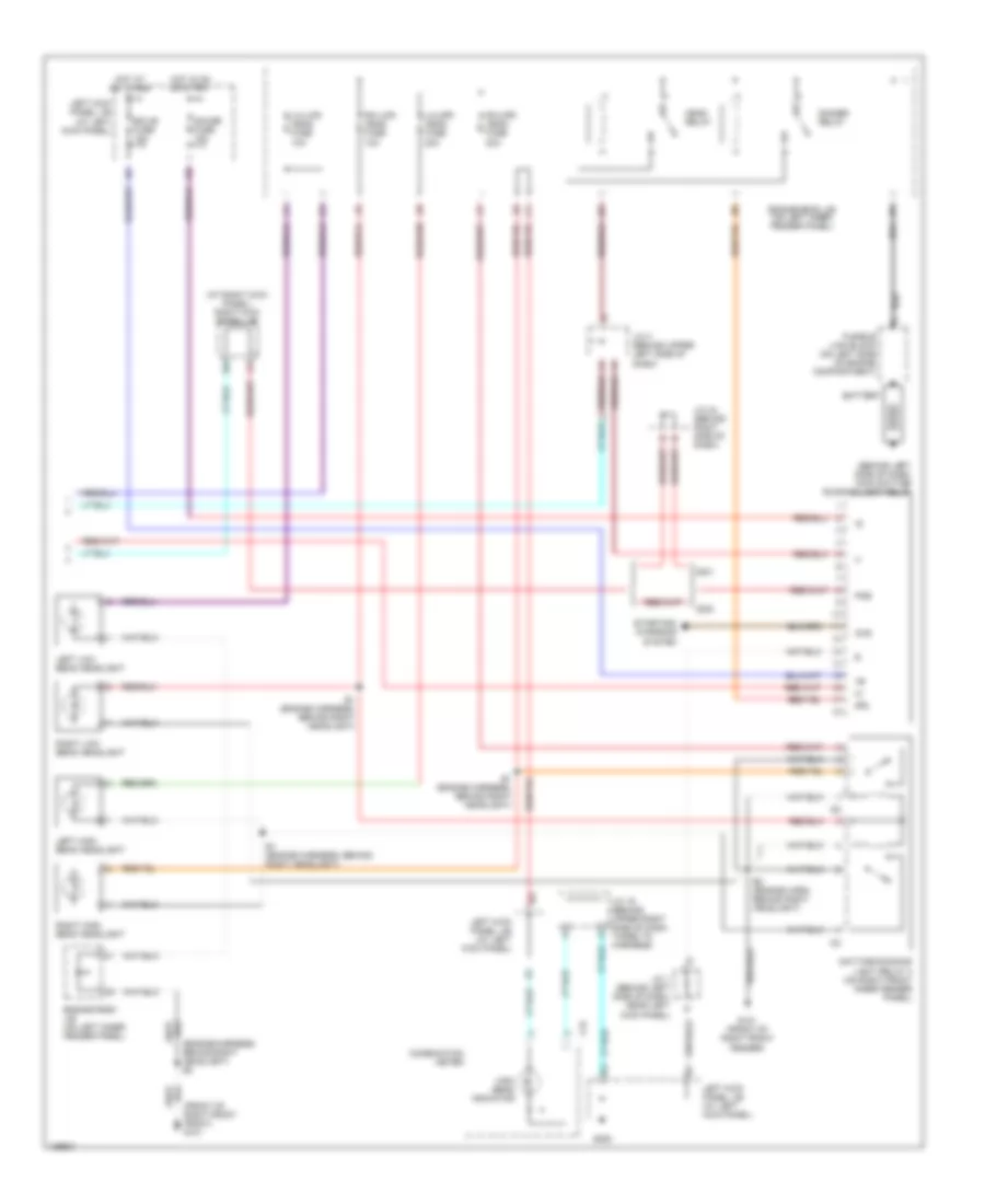
Headlight Wiring Diagram (1 of 2) for Toyota Land Cruiser 2001
List of elements for Headlight Wiring Diagram (1 of 2) for Toyota Land Cruiser 2001:
- A14
- A15
- A18
- A19
- Auto
- Automatic light control sensor (w/ auto lamps) (on top right side of dash)
- Becu
- Combination switch
- Cty
- D10
- Dcy
- Dimmer switch
- E19
- E2 (engine harness, behind right headlight)
- Ecu-b1 fuse 10a
- Ecu-ig fuse 15a
- Engine room j/b (on left inner fender panel)
- Exterior lights system
- F11
- Flash
- Fog light switch
- Fog lights
- Fr fog fuse 15a
- Fr fog relay
- G101 (front of right front fender)
- G103 (right front fender apron)
- G200
- G203
- Gnd1
- H10
- Head
- High
- Hot at all times
- Hot in on or start
- Hry
- Instrument ecu (w/o auto lamps) (behind center of dash)
- J/c 10 (behind upper left side of dash)
- J/c 11 (behind upper left side of dash)
- J/c 19 (behind upper right side of dash, taped to harness)
- J/c 27 (behind upper right side of dash, taped to harness)
- J/c 29 (behind upper right side of dash, taped to harness)
- J/c 9 (behind upper left side of dash)
- J11
- Left front door courtesy switch
- Left front foglight
- Left kick panel j/b (at left kick panel)
- Light control switch
- Low
- N15
- N17
- Off
- P25
- P78
- Parking brake switch (on base of park brake lever)
- Right front foglight
- Right kick panel j/b (at right kick panel)
- Sig
- Tail
- Try
- W/ auto lamps
- W/o auto lamps
Headlight Wiring Diagram (2 of 2) for Toyota Land Cruiser 2001
List of elements for Headlight Wiring Diagram (2 of 2) for Toyota Land Cruiser 2001:
- (at right kick panel) right kick panel j/b
- (behind left side of dash) main daytime running light relay
- (engine harness, behind right headlight) e2
- (front of right front front) g101
- Battery
- C15
- Chg
- Combination meter
- Daytime running light relay 3 (on right front inner fender panel)
- Dimmer relay
- Drl
- E1 (engine harness, behind right headlight)
- E2 (engine harn, behind right headlight)
- Ecu-b fuse 15a
- Engine room j/b (on left inner fender panel)
- Fusible link block (on left side of engine compartment)
- G101 (front of right front fender)
- G200
- Gauge fuse 15a
- Head relay
- High beam indicator
- Hot at all times
- Hot in on or start
- I34
- J/c 1 (behind left side of dash, near left kick panel)
- J/c 19 (behind upper right side of dash, taped to harness)
- J/c 3 (behind upper left side of dash)
- J/c 44 (behind right side of dash)
- Left high beam headlight
- Left kick panel j/b (at left kick panel)
- Left low beam headlight
- Lh-lwr head fuse 10a
- Lh-upr head fuse 20a
- Pkb
- Rh-lwr head fuse 10a
- Rh-upr head fuse 20a
- Right high beam headlight
- Right low beam headlight
- Starting/ charging system
HORN
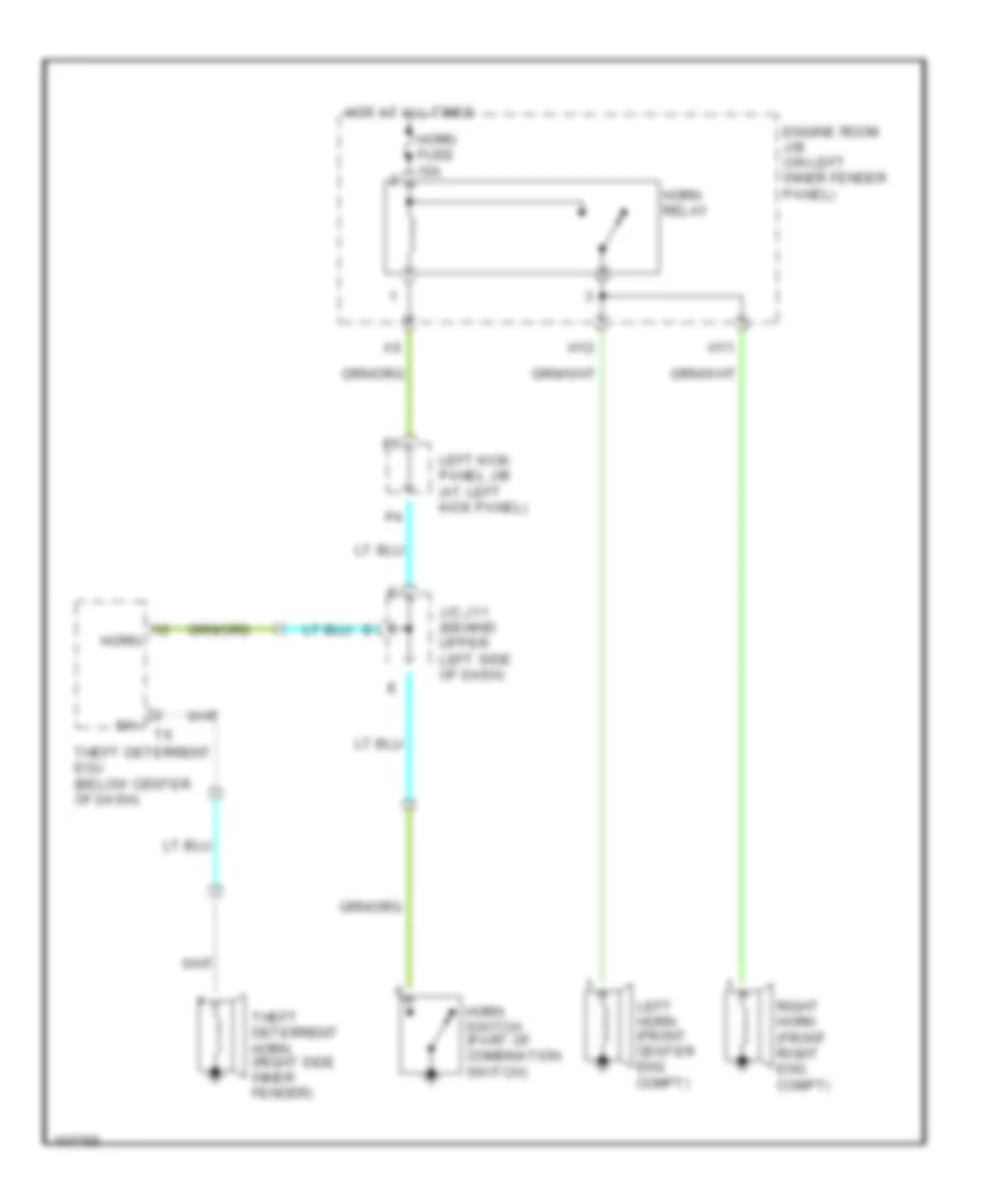
Horn Wiring Diagram for Toyota Land Cruiser 2001
List of elements for Horn Wiring Diagram for Toyota Land Cruiser 2001:
- Engine room j/b (on left inner fender panel)
- H11
- H12
- Horn
- Horn fuse 10a
- Horn relay
- Horn switch (part of combination switch)
- Hot at all times
- J/c j11 (behind upper left side of dash)
- Left horn (front center eng compt)
- Left kick panel j/b (at left kick panel)
- Right horn (front right eng compt)
- Sh-
- Theft deterrent ecu (below center of dash)
- Theft deterrent horn (right side inner fender)
INSTRUMENT CLUSTER
Instrument Cluster Wiring Diagram (1 of 2) for Toyota Land Cruiser 2001
List of elements for Instrument Cluster Wiring Diagram (1 of 2) for Toyota Land Cruiser 2001:
- (w/o vsc)
- 2 ind
- 2nd strt ind
- 4wd ind
- A/t oil temp ind
- A/t p
- A10
- A11
- A12
- A13
- A14
- A15
- A16
- A17
- A18
- A19
- A20
- Anti-lock brakes system
- B10
- B11
- B12
- B13
- B14
- B15
- B16
- B17
- B18
- B19
- B20
- Brake ind
- C10
- C11
- C12
- C13
- C14
- C15
- C16
- C17
- C18
- C19
- C20
- Center diff ind
- Charge ind
- Combination meter
- Cruise control system
- Cruise ind
- D ind
- D10
- D11
- D12
- D13
- D14
- D15
- D16
- D17
- D18
- D19
- D20
- Door ind
- E10 (engine harn, rear of engine)
- Ect pwr ind
- Ecu-b fuse 15a
- Engine controls system
- Engine controls, transmissions systems (speed signal)
- Exterior lights system
- Fuel gauge
- Fuel ind
- G120 (rear side of right cylinder head)
- G200
- Gauge fuse 15a
- Headlights system
- High beam ind
- Hot at all times
- Hot in on or start
- I15 (dash harn, right end of dash)
- Ign fuse 10a
- Illum
- Interior lights system
- J/c 14 (left side of dash)
- J/c 17 (behind upper right side of dash)
- J/c 19 (behind upper center of dash)
- J/c 29 (behind upper right side of dash)
- J/c 9 (behind upper left side of dash)
- L ind
- Left kick panel j/b
- Left kick panel j/b (left kick panel)
- Left turn ind
- Malfunction ind
- N ind
- O/d off ind
- Odo/ trip
- Oil pressure gauge
- P ind
- P26
- P55
- P56
- P83
- R ind
- Rear diff ind
- Right turn ind
- Seat belt ind
- Speedo- meter
- Srs ind
- Starting/charging system
- Tacho- meter
- To abs ind (diagram 2 of 2)
- To combi- nation meter (diagram 2 of 2)
- Transmissions system
- Vehicle speed sensor (left side of transmission)
- Volt- meter
- W/ vsc
- W/o vsc
- Warning systems
- Water temp gauge
Instrument Cluster Wiring Diagram (2 of 2) for Toyota Land Cruiser 2001
List of elements for Instrument Cluster Wiring Diagram (2 of 2) for Toyota Land Cruiser 2001:
- (upper left side of dash) j/c 29
- (upper left side of dash) j/c 9
- (upper right side of dash) j/c 17
- (upper right side of dash) j/c 20
- A/t indicator light switch
- Abs ind
- Active trac ind
- Anti-lock brake system
- Brake fluid level warning switch
- C11
- C12
- C13
- C14
- Combination meter
- D10
- E14 (left rear of engine compt)
- Ecu-b1 fuse 20a
- Engine room j/b
- From pin d17 (diagram 1 of 2)
- From water temperature gauge (diagram 1 of 2)
- Fuel sender (in fuel tank)
- G103 (right front fender apron)
- G120 (rear side of right cylinder head)
- G200
- Hot at all times
- J/c 12 (upper left side of dash)
- J/c 14 (upper center of dash)
- J/c 19 (upper right side of dash)
- J/c 25 (behind glove box)
- J/c 26 (upper right side of dash)
- J/c 27 (upper right side of dash)
- J/c 29 (upper right side of dash)
- J/c 43 (upper left side of dash)
- J/c 7 (behind upper center of dash)
- Left front door courtesy switch
- Left kick panel j/b
- N11
- N15
- N17
- Nca
- Oil pressure sender (lower left front side of engine)
- P10
- P62
- P76
- P77
- P78
- Parking brake switch (base of park brake lever)
- Slip ind
- Unlock warning switch
- Vsc off ind
- Vsc trac ind
- W/ vsc
- W/o vsc
- Water temperature sender (on top right side of engine)
INTERIOR LIGHTS
Courtesy Lamps Wiring Diagram (1 of 3) for Toyota Land Cruiser 2001
List of elements for Courtesy Lamps Wiring Diagram (1 of 3) for Toyota Land Cruiser 2001:
- (upper center of dash) junction connector j/c 14
- A10
- A11
- A13
- A14
- A20
- B10
- B11
- B15
- B18
- Becu
- Dcy
- Disw
- Dkl
- Dku
- Dml
- Dmu
- Frcl
- Frrm
- G11
- G15
- G16
- G17
- G18
- G19
- G200
- G203
- Gnd1
- I55
- I66
- I67
- I68
- I69
- I70
- Instrument ecu (behind center of dash)
- Junction connector j/c 12 (upper left side of dash)
- Junction connector j/c 14 (upper center of dash)
- Junction connector j/c 15 (upper center of dash)
- Junction connector j/c 26 (upper right side of dash) d
- Junction connector j/c 27 (upper right end of dash) c
- Junction connector j/c 29 (upper right side of dash)
- Ksw
- Kyil
- L11
- L12
- Left door key lock & unlock switch
- Left door lock control switch (power window master switch)
- Left kick panel j/b (at left kick panel)
- Lmry
- P59
- P74
- P75
- Pcy
- Pisw
- Pkl
- Pku
- Pml
- Pmu
- Red
- Right door key lock & unlock switch
- Right door lock control switch
- Right front door courtesy light
- Right kick panel j/b (at right kick panel)
- Right rear door courtesy light
- Rlcl
- Rlcy
- Rrcl
- Rrcy
- Sig
- Ul3
- Wireless door lock ecu (behind left of dash)
Courtesy Lamps Wiring Diagram (2 of 3) for Toyota Land Cruiser 2001
List of elements for Courtesy Lamps Wiring Diagram (2 of 3) for Toyota Land Cruiser 2001:
- (1999) (2000,2001)
- (upper right side of dash) junction connector j/c 19
- Back door courtesy switch
- Back door key lock & unlock switch
- C12
- C15
- D10
- Dome fuse 10a
- Dome relay
- E13
- E20
- Ecu-b1 fuse 10a 20a
- Ecu-ig fuse 15a
- G301 (under passen- gers seat)
- G404 (rear of left quarter panel)
- Hot at all times
- Hot in start or run
- I53
- I65
- Junction connector j/c 10 (upper left side of dash)
- Junction connector j/c 12 (upper left side of dash)
- Junction connector j/c 27 (upper right end of dash)
- Junction connector j/c 29 (upper right side of dash)
- Junction connector j/c 30 (upper right side of dash)
- Junction connector j/c 32 (top of left rear wheelwell)
- Junction connector j/c 33 (top of left rear wheelwell)
- Junction connector j/c 34 (top of left rear wheel- well)
- Junction connector j/c 9 (upper left side of dash)
- Left front door courtesy switch
- Left kick panel j/b (at left kick panel)
- Left rear door courtesy switch
- Meter connector
- N17
- Open door warning light
- P20
- P24
- P25
- P78
- Red
- Right front door courtesy switch
- Right kick panel j/b (at right kick panel)
- Right rear door courtesy switch
Courtesy Lamps Wiring Diagram (3 of 3) for Toyota Land Cruiser 2001
List of elements for Courtesy Lamps Wiring Diagram (3 of 3) for Toyota Land Cruiser 2001:
- (at left kick panel) left kick panel j/b
- (at right kick panel) right kick panel j/b
- (body harn, center front of roof) b7
- A13
- B2 (body harn, inside left front door)
- Door
- Front interior light & rear personal light
- Front personal light
- G200
- G203
- I56
- Ignition key cylinder light
- Junction connector j/c 1 (left end of dash)
- Junction connector j/c 10 (upper left side of dash)
- Junction connector j/c 9 (upper left side of dash)
- L13
- Left front door courtesy light
- Left front door lock motor & door unlock detection switch
- Left kick panel j/b (at left kick panel)
- Left rear door courtesy light
- Left vanity light
- N10
- P18
- P27
- P60
- Rear interior light
- Red
- Right front door lock motor & door unlock detection switch
- Right kick panel j/b (at right kick panel)
- Right vanity light
- Unlock warning switch
Instrument Illumination Wiring Diagram for Toyota Land Cruiser 2001
List of elements for Instrument Illumination Wiring Diagram for Toyota Land Cruiser 2001:
- (1999)
- (2000)
- (dash harn, left side of dash) i3
- (upper center of dash) junction connector j/c 15
- (upper right side of dash) junction connector j/c 26
- 1999, 2000
- 2000,
- A/c amplifier
- A/t shift lever illumination
- A10
- A22
- Ashtray illumination
- C20
- C22
- Center ecu
- Cigarette lighter illumination
- Combination meter
- Driver's seat heater switch
- Electronically controlled transmission pattern select switch
- Exterior lights system
- G200
- G301 (under passenger's seat)
- Glove box light
- Hot at all times
- I10 (dash harn, upper center of dash)
- I11 (dash harn, left side of radio)
- I13
- I13 (dash harn, right side of center console)
- I18 (dash harn, right side of center console)
- I3 (dash harn, left side of dash)
- I4 (dash harn, left side of dash)
- Ill-
- J/c 27 (upper right end of dash)
- J/c 28 (upper right end of dash)
- Junction connector j/c 14 (upper center of dash)
- Junction connector j/c 19 (behind center of dash, taped to harn)
- Junction connector j/c 35 (top of left rear wheelwell)
- Junction connector j/c 37 (behind left rear wheelwell)
- Junction connector j/c 38 (behind right rear wheelwell)
- Junction connector j/c 39 (behind right rear wheelwell)
- Junction connector j/c 7 (behind upper center of dash)
- Left kick panel j/b (at left kick panel)
- Left power quarter window switch
- Multi-display (2001 w/ nav)
- O10
- Passenger's seat heater switch
- Radio & player (1999, 2000)
- Radio & player (2001)
- Rear a/c control switch
- Rear heater switch
- Remote control mirror switch
- Rheostat
- Right power quarter window switch
- Stereo component amplifier (1999, 2000)
- Tail fuse 15a
- Tail relay
- W/ power rear quarter window
- W/ rear air conditioning
- W/o power rear quarter window
- W/o rear air conditioning
- W/rear air conditioning
NAVIGATION
Navigation Wiring Diagram for Toyota Land Cruiser 2001
List of elements for Navigation Wiring Diagram for Toyota Land Cruiser 2001:
- (in left front door)
- +b1
- Acc
- Aui+
- Aui-
- Auo+
- Auo-
- Braided
- C14
- C15
- C27
- Center ecu (behind center of dash)
- Cigar fuse 15a
- Combination meter
- D22
- D32
- Data link connector 1 (right inner fender panel)
- Data link connector 3 (left side of dash)
- Dvd automatic changer
- E11
- E17
- Ecu-b fuse 15a
- Ecu-ig fuse 15a
- Engine room j/b block (left inner fender panel)
- Fl+
- Fl-
- Front seat)
- G200
- G300 (under driver's seat)
- G301 (under front passenger's seat)
- Gateway ecu (behind right side of dash)
- Gauge fuse 15a
- Gnd
- Gnd1
- Gtx+
- Gtx-
- Hot at all times
- Hot in run or start
- I34
- I5 (behind left side of dash, near instrument cluster)
- I6 (upper right side of dash)
- Junction connector j/c 14 (upper left center of dash)
- Junction connector j/c 18 (right center of dash)
- Junction connector j/c 19 (right side of dash)
- Junction connector j/c 44 (upper right center of dash)
- Junction connector j/c 7 (upper left center of dash)
- Left front door speaker
- Left kick panel j/b (at left kick panel)
- Left tweeter
- Mpd1
- Mpd2
- Mpx+
- Mpx-
- Multi-display
- N15
- Navigation ecu (under right
- Ntsc
- P83
- Park/neutral position switch (left side of transmission)
- Parking brake switch (base of park brake lever)
- Pkb
- Pnk
- R34
- Radio & player
- Radio fuse 20a
- Red
- Rev
- Right kick panel j/b (at right kick panel)
- Sgd1
- Sgnd
- Spd
- Stereo component amplifier (under right front seat)
- Sync
- Tx+
- Tx-
- Tx1+
- Tx1-
- Tx3+
- Tx3-
POWER ANTENNA
Power Antenna Wiring Diagram for Toyota Land Cruiser 2001
List of elements for Power Antenna Wiring Diagram for Toyota Land Cruiser 2001:
- Acc
- Ant
- Auto antenna control relay (behind glove box)
- Auto antenna motor (in right rear of engine compartment)
- B19
- Braid
- C20
- C22
- Center ecu (behind center of dash)
- Cig fuse 15a
- D22
- Down
- E17
- Ecu-ig fuse 15a
- Engine room j/b (on left inner fender panel)
- G200
- G203
- Gnd
- Hot at all times
- Hot in acc or on
- Hot in on or start
- J/c 1 (1998-99) (behind left center of dash, near left kick panel)
- J/c 30 (right side of dash)
- J/c 7 (2000-01) (behind upper center of dash)
- Left kick panel j/b (at left kick panel)
- Radio & ant+ player
- Radio fuse 20a
- Red
- Right kick panel j/b (at right kick panel)
- S-antd
- S-antu
- Sdwn
- Sgnd
- Sig
- Sup
- Vcc
- W/ navigation system
- W/o navigation system
POWER DISTRIBUTION
Power Distribution Wiring Diagram (1 of 2) for Toyota Land Cruiser 2001
List of elements for Power Distribution Wiring Diagram (1 of 2) for Toyota Land Cruiser 2001:
- (on left inner fender panel) engine room j/b
- A/c fuse 20a
- Abs 1 fuse 50a
- Abs 2 fuse 40a
- Abs mtr1 relay
- Abs mtr2 relay
- Abs sol relay
- Acc fuse 50a
- Acc relay
- Air conditioning system
- Alt fuse 140a
- Alt-s fuse 7.5a
- Am 1 num- ber 1 fuse 80a
- Am 1 num- ber 2 fuse 20a
- Am2 fuse 30a
- Anti-theft, exterior lights systems
- Battery
- Cds fan fuse 20a
- Cooling fans, air conditioning systems
- Cooling fans, air conditioning, warning systems
- Cruise control, transmissions, engine controls systems
- D10
- Dimmer relay
- E10
- E13
- E14
- E15
- E17
- Ecu-b1 fuse 20a
- Efi or ecd fuse 20a
- Efi or ecd relay
- Engine room j/b (on left inner fender panel)
- Exterior lights system
- From a engine room j/b (diagram 1 of 2)
- From g engine room j/b (diagram 1 of 2)
- Fusible link block
- Haz-trn fuse 15a
- Head relay
- Headlights, instrument cluster systems
- Horn fuse 10a
- Horn relay
- Htr fuse 60a
- Ign 1 no 1 relay
- Ign 1 no 2 relay
- Interior lights, headlights, door locks, power windows, power tops, anti-theft, exterior lights, instrument cluster air, conditioning, warning systems
- J/b 2 fuse 100a
- L19
- Lh-lwr head fuse 10a
- Lh-upr head fuse 20a
- Mir htr fuse 15a
- Mir htr relay
- Power antenna, sound systems
- Radio fuse 20a
- Rh-lwr head fuse 10a
- Rh-upr head fuse 20a
- Seat htr fuse 15a
- Seats system
- Starter fuse 30a
- Starter relay
- Starting/ charging system
- Throttle fuse 15a
- To engine room j/b (diagram 1 of 2)
- To ignition switch (diagram 2 of 2)
- To junction connector j/c 4 (diagram 2 of 2)
- To left kick panel j/b (diagram 2 of 2)
Power Distribution Wiring Diagram (2 of 2) for Toyota Land Cruiser 2001
List of elements for Power Distribution Wiring Diagram (2 of 2) for Toyota Land Cruiser 2001:
- (at left kick panel) left kick panel j/b
- (rear of left quarter panel) g404
- Acc
- Ahc-ig fuse 20a (2001)
- Air cond- itioning system
- Anti-lock brakes system
- Anti-lock brakes,
- Anti-lock brakes, power antenna, interior lights, exterior lights, door locks, power tops, power windows, shift interlock, anti- theft, headlights, electronic power steering systems
- B10
- B11
- B12
- B17
- Cigar fuse 15a
- Cigarette lighter
- D/l (du) relay
- D/l (l) relay
- D/l (u) relay
- D14
- D18
- D21
- D22
- Data link connector 3
- Defog fuse 20a
- Defog relay
- Diff fuse 20a
- Dome fuse 10a
- Dome relay
- Door locks, power tops, seats, power windows, electronic power steering systems
- Ecu-b fuse 15a
- Ecu-ig fuse 15a
- Engine controls system
- Engine controls, exterior lights, cruise control, electronic suspension, shift interlock, anti-lock brakes systems
- Exterior lights, transmissions, starting/charging, cruise control, instrument cluster, engine controls, headlights, warning systems, defogger, door locks, power windows systems
- F12
- F14
- Fr fog fuse 15a
- Fr fog relay
- From engine room j/b (diagram 1 of 2)
- From engine room j/b d (diagram 1 of 2)
- From engine room j/b e (diagram 1 of 2)
- From engine room j/b f (diagram 1 of 2)
- From fusible link block (diagram 1 of 2)
- From left kick panel j/b (diagram 2 of 2)
- From left l kick panel j/b (diagram 2 of 2)
- Front power outlet
- G200
- Gauge fuse 15a
- I/up fuse 7.5a
- I10 (dash harn, upper left center of dash)
- I6 (dash harn, behind instrument cluster)
- Idle up diode
- Ign fuse 10a
- Ignition coils & igniters
- Ignition switch
- Junction connector j/c 32 (above left rear wheelwell)
- Junction connector j/c 4 (upper left side of dash)
- Junction connector j/c 7 (behind upper center of dash)
- Left kick panel j/b (at left kick panel)
- Lock
- Luggage compartment power outlet
- Mirr fuse 10a
- Mirrors system
- N14
- O13
- Obd fuse 10a
- P25
- P26
- P37
- P53
- P55
- P83
- Power antenna, instrument cluster, cooling fans, air conditioning, sound, mirrors, shift inter- lock systems
- Power fuse 40a
- Power relay
- Pwr outlet fuse 15a
- Rear control box power outlet
- Red
- Rr a/c fuse 30a
- Rr htr fuse 10a
- Rr htr relay
- Run
- Srs fuse 15a
- Start
- Starting system
- Stop fuse 15a
- Tail fuse 15a
- Tail relay
- To left kick panel j/b (diagram 2 of 2)
- Transmissions system
- Wiper fuse 20a
- Wiper/ washer system
POWER DOOR LOCKS
Power Door Lock Wiring Diagram (1 of 3) for Toyota Land Cruiser 2001
List of elements for Power Door Lock Wiring Diagram (1 of 3) for Toyota Land Cruiser 2001:
- (behind left of dash) (w/ keyless entry system) wireless door lock ecu
- (behind left side of dash) j/c 1
- (behind upper right side of dash) j/c 28
- A - i19 b - i20 c - i21
- A10
- A11
- A14
- A20
- Acy
- B12
- B13
- B14
- B18
- Becu
- C11
- Cty
- Dcy
- Ddry
- Disw
- Dkl
- Dku
- Dlry
- Dml
- Dmu
- Dury
- Exterior lights system
- G16
- G17
- G18
- G19
- G200
- G203
- Gnd
- Gnd1
- I39
- I46
- I66
- I67
- I68
- I69
- Instrument ecu (behind center of dash)
- J/c 10 (behind upper left side of dash)
- J/c 14 (behind upper center of dash)
- J/c 15 (behind upper center of dash)
- J/c 17 (behind upper right side of dash)
- J/c 26 (behind upper right side of dash) d
- J/c 27 (behind upper right side of dash) c
- J/c 29 (behind upper right side of dash)
- J/c 3 (behind upper left side of dash)
- J/c 4 (behind upper left side of dash)
- J/c 43 (behind upper left side of dash)
- J/c 9 (behind upper left side of dash)
- Ksw
- L11
- L12
- Left door key lock & unlock switch
- Left door lock control switch (power window master switch)
- Left kick panel j/b (at left kick panel)
- Lswd
- Lswp
- Lswr
- P59
- P74
- P75
- Pcy
- Pisw
- Pkl
- Pku
- Pml
- Pmu
- Right door key lock & unlock switch
- Right door lock control switch
- Right kick panel j/b (at right kick panel)
- Rlcy
- Rrcy
- Sig
- Trly
- Try
- Ul3
Power Door Lock Wiring Diagram (2 of 3) for Toyota Land Cruiser 2001
List of elements for Power Door Lock Wiring Diagram (2 of 3) for Toyota Land Cruiser 2001:
- (behind upper right side of dash) j/c 19
- (dash harn, left side of dash)
- (rear of left quarter panel) g404
- (w/ navigation)
- (w/o navigation)
- B15
- B17
- Back door courtesy switch
- Back door key lock & unlock switch
- C20
- Center ecu (behind center of dash)
- D/l (du) relay
- D/l (l) relay
- D/l (u) relay
- D10
- E12
- E20
- Ecu-b fuse 15a
- Ecu-b1 fuse 20a
- Ecu-ig fuse 15a
- Engine controls system
- Engine room j/b (on left inner fender panel)
- G200
- G404 (rear of left quarter panel)
- Gauge fuse 15a
- Hot at all times
- Hot in run or start
- I42
- I43
- I53
- I65
- J/c 10 (behind upper left side of dash)
- J/c 21 (behind upper right side of dash)
- J/c 27 (behind upper right side of dash)
- J/c 33 (above left rear wheelwell)
- J/c 34 (above left rear wheelwell)
- J/c 9 (behind upper left side of dash)
- Left front door courtesy switch
- Left kick panel j/b (at left kick panel)
- Left rear door courtesy switch
- N17
- P20
- P22
- P23
- P25
- P26
- P78
- P81
- Power fuse 40a
- Right front door courtesy switch
- Right kick panel j/b (at right kick panel)
- Right rear door court- esy switch
Power Door Lock Wiring Diagram (3 of 3) for Toyota Land Cruiser 2001
List of elements for Power Door Lock Wiring Diagram (3 of 3) for Toyota Land Cruiser 2001:
- (at left kick panel) left kick panel j/b
- (at right kick panel) right kick panel j/b
- (body harn, left rear door sill)
- (rear
- (under driver's seat) g300
- +b1
- +b2
- A11
- A12
- B14
- B15
- Back door lock motor & door unlock detection switch
- Cty
- Dswd
- Dswh
- Dswp
- Engine hood courtesy switch (on top center of radiator support)
- Engine room j/b (on left inner fender panel)
- Exterior lights
- F10
- G101 (front of right front fender)
- G12
- G13
- G200
- G203
- G301 (under passenger's seat)
- G404
- Haz-trn fuse 15a
- Head
- Headlights
- Horn
- Horns
- Hot at all times
- I56
- Ind
- J/c 10 (behind upper left side of dash)
- J/c 19 (behind upper right side of dash)
- J/c 3 (behind upper left side of dash)
- J/c 35 (above left rear wheelwell)
- J/c 7 (behind upper center of dash)
- J/c 9 (behind upper left side of dash)
- Ksw
- L13
- Left front door lock motor & door unlock detection switch
- Left kick panel j/b (at left kick panel)
- Left rear door lock motor & door unlock detection switch
- Lswd
- Lswp
- Lswr
- Lug
- Of left quarter panel)
- P18
- Right front door lock motor & door unlock detection switch
- Right kick panel j/b (at right kick panel)
- Right rear door lock motor & door unlock detection switch
- Sh-
- Tail
- Theft deterrent ecu (w/ anti- theft) (behind center of dash)
- Theft deterrent horn (on right side inner fender panel)
- Ul2
- Ul3
- Unlock warning switch
POWER MIRRORS
Power Mirror Wiring Diagram for Toyota Land Cruiser 2001
List of elements for Power Mirror Wiring Diagram for Toyota Land Cruiser 2001:
- Down
- G200
- Hot in acc or on
- I20
- I21
- I24
- J/c 13 (behind upper center of dash)
- J/c 19 (behind upper right side of dash)
- J/c 20 (behind upper right side of dash)
- Left
- Left kick panel j/b (at left kick panel)
- Left remote control mirror
- M12
- Mir fuse 10a
- Operation switch
- P31
- P32
- P33
- P42
- P45
- Remote control mirror switch
- Right
- Right kick panel j/b (at right kick panel)
- Right remote control mirror
- Select switch
POWER SEATS
Heated Seats Wiring Diagram for Toyota Land Cruiser 2001
List of elements for Heated Seats Wiring Diagram for Toyota Land Cruiser 2001:
- (dash harn, front of center console)
- 1998-99
- 2000-01
- Driver's seat heater
- Driver's seat heater switch
- Engine room j/b (on left inner fender panel)
- Front passenger's seat heater
- Front passenger's seat heater switch
- G200
- G300 (under driver's seat)
- G301 (under front passenger's seat)
- Hot at all times
- I13 (dash harn, right side of center console)
- J/c 1 (left end of dash)
- Left kick panel j/b (at left kick panel)
- Seat htr fuse 15a
Power Seats Wiring Diagram for Toyota Land Cruiser 2001
List of elements for Power Seats Wiring Diagram for Toyota Land Cruiser 2001:
- A13
- B20 (body harness, under left front seat)
- B21
- Down
- Driver's lumbar support control motor (under seat)
- Driver's lumbar support control switch
- Driver's power seat control switch
- Front
- Front vertical
- Front vertical control motor (under seat)
- G300 (under driver's seat)
- G301 (under passenger's seat)
- Hot at all times
- Left kick panel j/b (at left kick panel)
- N14
- Passenger's power seat control switch
- Power fuse 40a
- Rear
- Rear vertical
- Rear vertical control motor (under seat)
- Reclining
- Reclining control motor (under seat)
- Red
- Right kick panel j/b (at right kick panel)
- Slide
- Slide control motor (under seat)
POWER TOP/SUNROOF
Moonroof Wiring Diagram for Toyota Land Cruiser 2001
List of elements for Moonroof Wiring Diagram for Toyota Land Cruiser 2001:
- (2000) (2001)
- B17
- Becu
- Close
- D10
- Dcy
- Down
- Ecu-b1 fuse 10a
- Ecu-ig fuse 15a
- Engine room j/b (left inner fender panel)
- G200
- G203
- Gnd1
- Hot at all times
- Hot in on or start
- I1 (dash harness, left end of dash)
- I19
- I21
- I38
- I47
- I65
- Instrument ecu (behind center of dash)
- J/c 10 (behind upper left side of dash)
- J/c 15 (behind upper center of dash)
- J/c 17 (behind upper right side of dash)
- J/c 19 (behind upper right side of dash)
- J/c 27 (behind upper right side of dash)
- J/c 28 (behind upper right side of dash)
- J/c 29 (behind upper right side of dash)
- J/c 9 (behind upper left side of dash)
- Left front door courtesy switch
- Left kick panel j/b (at left kick panel)
- Moon roof control ecu (on roof, in front of moon roof)
- Moon roof control switch
- N17
- Open
- P25
- P78
- P80
- Pcy
- Power fuse 40a
- Power relay
- Pwry
- Red
- Right front door courtesy switch
- Right kick panel j/b (at right kick panel)
- Sig
- Tilt & telescopic ecu (behind left side of dash)
POWER WINDOWS
Power Windows Wiring Diagram for Toyota Land Cruiser 2001
List of elements for Power Windows Wiring Diagram for Toyota Land Cruiser 2001:
- (upper right side of dash)
- A13
- B20
- Becu
- D10
- D11
- Dcy
- Ecu-b1 fuse 20a
- Ecu-ig fuse 15a
- Engine room j/b (left inner fender panel)
- G200
- G203
- G300 (under driver's seat)
- G301 (under passenger's seat)
- Gnd1
- Hot at all times
- Hot in on or start
- I19
- I21
- I38
- I47
- I65
- Instrument ecu (behind center of dash)
- J/c 10 (upper left side of dash)
- J/c 15 (behind center of dash)
- J/c 17 (upper right side of dash)
- J/c 19 (upper right side of dash)
- J/c 27 (upper right side of dash)
- J/c 28
- J/c 29 (upper right side of dash)
- J/c 3 (upper left side of dash)
- Left front door courtesy switch
- Left front power window motor
- Left kick panel j/b
- Left rear power window control switch
- Left rear power window motor
- Lmt
- N13
- N14
- N17
- P25
- P78
- P80
- Pct
- Pcy
- Pls
- Power fuse 40a
- Power main relay
- Power window master switch
- Pwr
- Pwry
- Red
- Right front door courtesy switch
- Right front power window control switch
- Right front power window motor
- Right kick panel j/b
- Right rear power window control switch
- Right rear power window motor
- Sel1
- Sel2
- Sgnd
- Sig
Rear Quarter Windows Wiring Diagram for Toyota Land Cruiser 2001
List of elements for Rear Quarter Windows Wiring Diagram for Toyota Land Cruiser 2001:
- (dash harn, left side of dash)
- G200
- Gauge fuse 15a
- Hot in start or run
- I18
- I19
- J/c 14 (upper center of dash)
- J/c 19 (upper right side of dash)
- J/c 40 (w/ rear a/c) (in back door)
- J/c 41 (w/o rear a/c) (in back door)
- Left kick panel j/b (at left kick panel)
- Left power quarter window switch
- Left power vent window motor
- N16
- P36
- P61
- P83
- Pnk
- Red
- Right kick panel j/b (at right kick panel)
- Right power quarter window switch
- Right power vent window motor
RADIO
Radio Wiring Diagrams, with Navigation for Toyota Land Cruiser 2001
List of elements for Radio Wiring Diagrams, with Navigation for Toyota Land Cruiser 2001:
- (door harn, in left front door) b2
- (under right front seat) g301
- Acc
- Amp
- Ant
- Aui
- Auo
- Auto antenna control relay
- Beep
- Cdl
- Cdr
- Cigar fuse 15a
- D10
- D22
- D26
- Dvd automatic changer
- E17
- Ecu-b1 fuse 20a
- Engine room j/b (left inner fender panel)
- Front door) b8
- G200
- Gnd
- Hot at all times
- Hot in run or acc
- Illum
- Interior lights system
- Junction connector j/c 7 (behind center of dash)
- Left front door speaker
- Left front tweeter speaker
- Left kick panel j/b (at left kick panel)
- Left kick panel j/b (left kick panel)
- Left rear door speaker
- Multi- display
- Mute
- Navigation ecu
- Nca
- Ntsc
- Pnk
- R35
- Radio & player
- Radio fuse 20a
- Red
- Right front door speaker
- Right front tweeter speaker
- Right rear door speaker
- Sgd1
- Sgnd
- Stereo component amplifier
- Tx1
- Txm
- Woofer speaker
Radio Wiring Diagrams, without Navigation for Toyota Land Cruiser 2001
List of elements for Radio Wiring Diagrams, without Navigation for Toyota Land Cruiser 2001:
- (under right front seat) g301
- Acc
- Amp
- Ant
- Auto antenna control relay
- Beep
- Cigar fuse 15a
- D22
- E17
- Engine room j/b (left inner fender panel)
- Front door) b2
- Front door) b8
- Gnd
- Hot at all times
- Hot in run or acc
- Illum
- Interior lights system
- Left front door speaker
- Left front tweeter speaker
- Left kick panel j/b (left kick panel)
- Left rear door speaker
- Mute
- Nca
- Pnk
- Radio & player
- Radio fuse 20a
- Red
- Right front door speaker
- Right front tweeter speaker
- Right rear door speaker
- Sgnd
- Stereo component amplifier
- Woofer speaker
SHIFT INTERLOCKS
Shift Interlock Wiring Diagram for Toyota Land Cruiser 2001
List of elements for Shift Interlock Wiring Diagram for Toyota Land Cruiser 2001:
- (2000) (2001)
- (2001) (2000)
- A c
- Acc
- B10
- Behind left side of dash)
- C a
- Cig fuse 15a
- D22
- Ecu-ig fuse 15a
- G200
- Hot at all times
- Hot in acc or on
- Hot in on or start
- J/c 43 (behind upper left side of dash)
- J/c 7 (behind upper center of dash)
- Key interlock solenoid (on steering column, behind ignition key cylinder)
- Kls+
- Left kick panel j/b (at left kick panel)
- O/d main switch & shift lock control ecu (below center console)
- Shift lock control switch
- Shift lock solenoid
- Sls+
- Sls-
- Stop fuse 15a
- Stoplight switch (on bracket, above brake pedal)
- Stp
STARTING/CHARGING
Charging Wiring Diagram for Toyota Land Cruiser 2001
List of elements for Charging Wiring Diagram for Toyota Land Cruiser 2001:
- A12
- Alt fuse 140a
- Alt-s fuse 7.5a
- Battery
- Battery ground
- C13
- Charge warning light
- Comb- ination meter
- D19
- Daytime running light relay (main) (behind left side of dash)
- Engine room j/b (on left inner fender panel)
- F10
- Fusible link block (left side of engine compt, near battery)
- Gauge fuse 15a
- Generator
- Hot in on or start
- Ign fuse 10a
- J10
- Left kick panel j/b (left kick panel)
- Nca
- P51
- P55
Starting Wiring Diagram for Toyota Land Cruiser 2001
List of elements for Starting Wiring Diagram for Toyota Land Cruiser 2001:
- Acc
- Am2 fuse 30a
- Battery
- Battery ground
- C14
- Combination meter
- D14
- E10
- Engine control module (behind right side of dash)
- Engine room j/b (left inner fender panel)
- Fusible link block (left side of engine compt near battery)
- G102
- Ignition switch
- Nca
- Off
- Park/neutral position switch (left side of transmission)
- Right end of dash) i15
- Start
- Starter
- Starter fuse 1 30a
- Starter relay
SUPPLEMENTAL RESTRAINTS
Supplemental Restraint Wiring Diagram for Toyota Land Cruiser 2001
List of elements for Supplemental Restraint Wiring Diagram for Toyota Land Cruiser 2001:
- (rear bank of right cylinder head) g117
- +sl
- +sr
- -sl
- -sr
- Acc
- Air bag squib (front passenger air bag assembly)
- Air bag squib (steering wheel pad)
- B13
- B16
- C10
- C14
- Center air bag sensor assembly (under front of center console)
- Combination meter
- D15
- Data link connector (dlc) 1 (partial) (on right side of engine compartment)
- Data link connector (dlc) 3 (partial) (behind left side of dash, right of steering column)
- Ecu-b fuse 15a
- G200
- Hot at all times
- Hot in acc or on
- Hot in on or start
- Ig2
- Ign fuse 10a
- J/c 16 (behind upper right side of dash)
- J/c 21 (behind upper right side of dash)
- J/c 29 (behind upper right side of dash)
- J/c 9 (behind upper left side of dash)
- Left front air bag sensor (on upper left side of radiator support crossbar)
- Left kick panel j/b (at left kick panel)
- Left pretensioner (at bottom of left "b" pillar)
- P26
- P50
- Pl+
- Pl-
- Pr+
- Pr-
- Right front air bag sensor (on upper right side of radiator support crossbar)
- Right pretensioner (at bottom of right "b" pillar)
- Sil
- Spiral cable
- Srs fuse 15a
- Srs warning light
TRANSMISSION
A/T Wiring Diagram for Toyota Land Cruiser 2001
List of elements for A/T Wiring Diagram for Toyota Land Cruiser 2001:
- (behind upper left side of dash)
- (behind upper right side of dash)
- (dash harn, upper right end of dash)
- (dash harn, upper right end of dash) i15
- (dash harn, upper right side of dash)
- (eng harn, rear of engine)
- (eng harn, rear of engine) e10
- (left side of transmission) (combination meter) vehicle speed sensor
- (on left inner fender panel)
- (rear bank of right cilynder head) ec
- +b1
- +bm
- 2 ind
- 2nd
- 2nd strt
- A/t oil temperature sensor (top of trans)
- A/t p
- Acc
- Accelerator position sensor (top front of engine)
- B10
- Batt
- C13
- Cl+
- Cl-
- D ind
- D21
- E01
- E02
- E03
- E10
- Ec (rear bank of right cylinder head)
- Ect pwr
- Efi or ecd fuse 20a
- Eft or efi relay
- Electronically controlled trans- mission solenoid (left side of trans)
- Electronically controlled transmission pattern select switch
- Engine control module (behind right side of dash)
- Engine controls (combination meter)
- Engine coolant temperature sensor (top front of engine)
- Engine room j/b
- Engine room j/b (left inner fender panel)
- Gauge fuse 15a
- Ge01
- Hot at all times
- Hot in on or start
- I12
- I14
- I15
- Ign fuse 10a
- Ignition switch
- Igsw
- Interior lights system
- J/c 17
- J/c 17 (behind upper right side of dash)
- J/c 20 (behind upper right side of dash)
- J/c 22 (behind upper right side of dash)
- J/c 25 (behind glove box)
- J/c 43
- J/c 43 (behind upper left side of dash)
- L ind
- Left kick panel j/b
- Me01
- Mrel
- N ind
- Nca
- Nco+
- Nco-
- Nsw
- O/d direct clutch speed sensor (left side of trans)
- O/d main switch
- O/d off
- Odlp
- Odms
- Off
- Oil
- Oil temp
- Oilw
- P ind
- P56
- Park/neutral position switch (left side of transmission)
- Pwr
- R ind
- Red
- Slt+
- Slt-
- Snwi
- Snwl
- Sp2+
- Sp2-
- Spd
- Speedo
- St2
- Sta
- Start
- Starting/ charging system
- Stop fuse 15a
- Stoplight switch (on bracket, above brake pedal)
- Stp
- Tfn
- Throttle control motor (on top left front of engine)
- Throttle fuse 15a
- Throttle position sensor (on throttle body assembly)
- Thw
- Transfer l position detection switch (left side of trans)
- Transfer n position detection switch (left side of trans)
- Vehicle speed sensor (electronically control trans.) (left side of trans)
- Vpa
- Vpa2
- Vta
- Vta2
Center & Rear Differential Locks Wiring Diagram for Toyota Land Cruiser 2001
List of elements for Center & Rear Differential Locks Wiring Diagram for Toyota Land Cruiser 2001:
- (dash harn, upper right end of dash) i15
- (rear side of right cyl head)
- 4wd
- A/t p indic
- Anti-lock brakes system
- B12
- Bk (under passenger's seat)
- Bm (rear of left quarter panel)
- C12
- C13
- C14
- Center diff indic
- Center differential lock control motor (on center differential)
- Center differential lock control relay (behind right side of dash)
- Center differential lock detection switch (on differential)
- Center differential lock switch
- Combination meter
- Diff fuse 20a
- E11
- Ec (rear side of right cylinder head)
- Engine controls system
- Engine controls system (vehicle speed sensor)
- Gauge fuse 15a
- Grd
- Hot in run or start
- I12
- I63
- Junction connector j/c 17 (upper center of dash)
- Junction connector j/c 20 (upper right side of dash)
- Left kick panel j/b (at left kick panel)
- P56
- P83
- Park/neutral position switch (on transmission)
- Rear diff indic
- Rear differential lock control ecu (behind right side of dash)
- Rear differential lock detection switch (on rear differential)
- Rear differential lock motor (on rear differential)
- Rear differential lock switch
- Rel1
- Rel2
- Rlp
- Spd
- Transfer "l" position detection switch (on left side of transmission)
- Transfer neutral position detection switch (on left side of transmission)
- W/ navigation
- W/o navigation
WARNING SYSTEMS
Warning System Wiring Diagrams for Toyota Land Cruiser 2001
List of elements for Warning System Wiring Diagrams for Toyota Land Cruiser 2001:
- (behind center of dash) j/c 14
- (behind upper right side of dash) j/c 29
- (behind upper right side of dash) j/c 30
- (under right front seat)
- A/c fuse 20a
- B20
- C12
- C13
- C9 c20
- C9 c22
- Center ecu (behind center of dash)
- Combination meter
- D10
- Ecu-b1 fuse 20a
- Engine room j/b (on left inner fender panel)
- G120 (rear side of right cylinder head)
- G200
- G300 (under driver's seat)
- G301
- Gauge fuse 15a
- Hot at all times
- Hot in on or start
- J/c 12 (behind upper left side of dash)
- J/c 14 (behind upper center of dash)
- J/c 19 (behind upper right side of dash)
- J/c 26 (behind upper right side of dash)
- J/c 27 (behind upper right side of dash)
- J/c 43 (behind upper left side of dash)
- J/c 7 (behind upper center of dash)
- J/c 9 (behind upper left side of dash)
- Left buckle switch
- Left front door courtesy switch
- Left kick panel j/b
- N17
- P78
- P83
- Right buckle switch
- Seat belt
- Seat belt warning occupant detection sensor (under right front seat)
- Unlock warning switch
- W/ navigation
- W/o navigation
WIPER/WASHER
Front Wiper/Washer Wiring Diagram for Toyota Land Cruiser 2001
List of elements for Front Wiper/Washer Wiring Diagram for Toyota Land Cruiser 2001:
- (right front fender apron) g103
- Combination switch
- Engine room j/b (on left inner fender panel)
- F14
- Front wiper motor (on right side of firewall)
- G200
- High
- Hot in run or start
- Int
- Int time
- J/c 19 (behind upper right side of dash)
- Left kick panel j/b (at left kick panel)
- Low
- Off
- Solid state
- Washer motor (on washer fluid reservoir)
- Washer switch
- Wiper fuse 25a
- Wiper switch
Rear Wiper/Washer Wiring Diagram for Toyota Land Cruiser 2001
List of elements for Rear Wiper/Washer Wiring Diagram for Toyota Land Cruiser 2001:
- B15
- B15 (body harn, in rear hatch)
- Combination switch
- E13
- Engine room j/b (on left inner fender panel)
- F14
- Front wiper/ washer circuit
- G200
- G404 (rear of left quarter panel)
- Hot in run or start
- I19
- I21
- Instrument ecu (behind center of dash)
- Int
- Left kick panel j/b
- Left kick panel j/b (at left kick panel)
- O13
- O15
- Off
- P19
- P28
- P29
- Rear wiper & washer switch
- Rear wiper motor (on center of rear door)
- Rear wiper relay (in center of liftgate)
- Washer 1
- Washer 2
- Washer motor (on washer fluid reservoir)
- Wiper fuse 25a

 Čeština
 Dansk
Dansk Deutsch
 Ελληνικά
 English
 English
 Español
 Suomi
Suomi Français
 Français
 עברית
עברית Hrvatski
 Magyar
 日本語
日本語 한국어
한국어 Nederlands
 Polski
 Português
 Português
 Română
 Русский
 Slovenčina
 Slovenščina
 Svenska
 Türkçe
 中文 (中国)