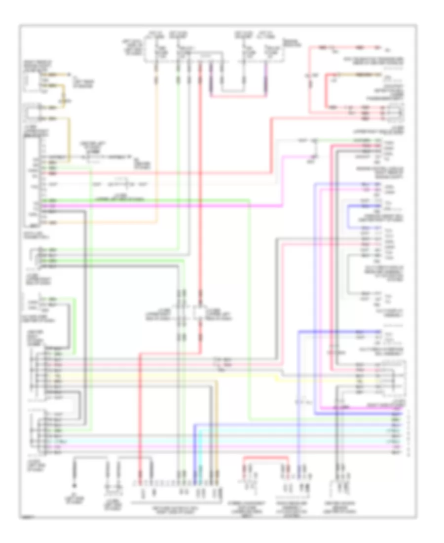
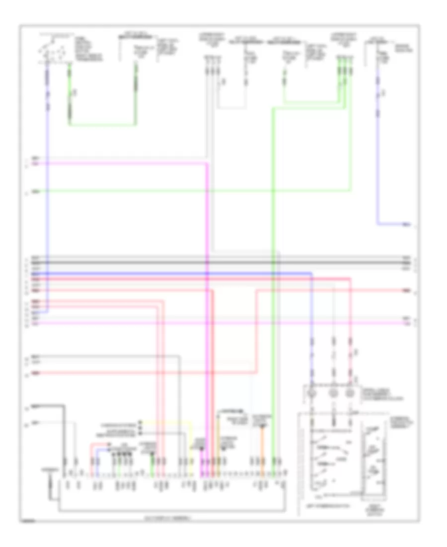
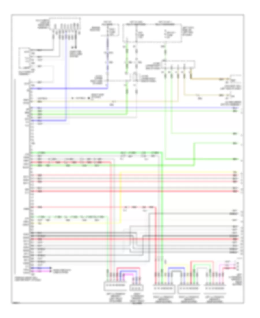
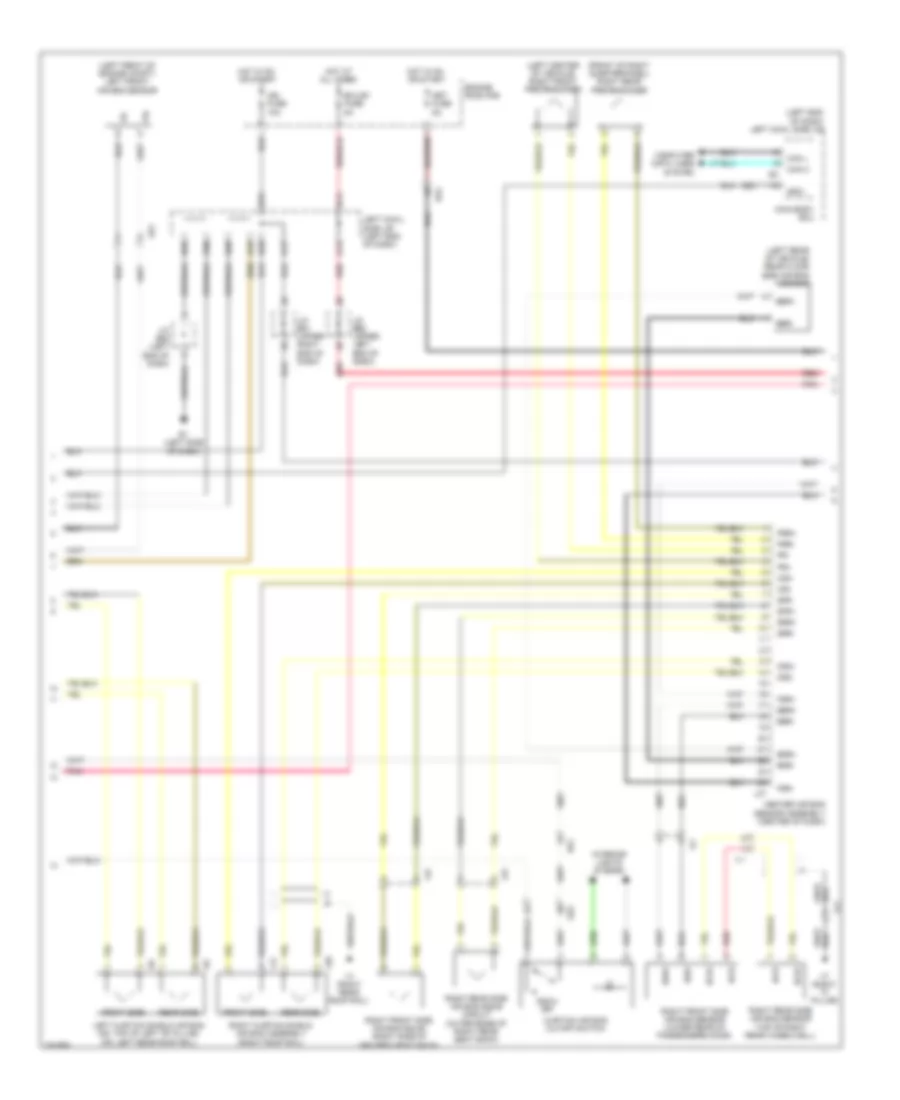
AIR CONDITIONING
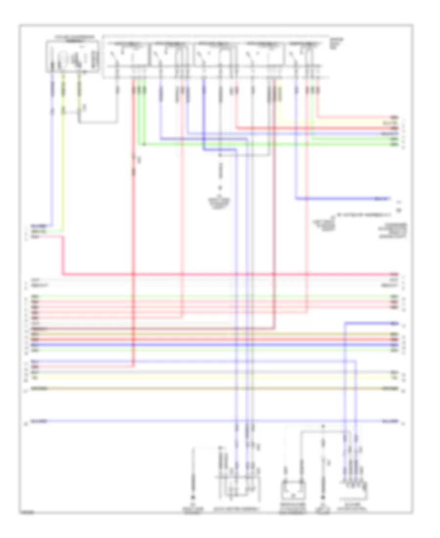
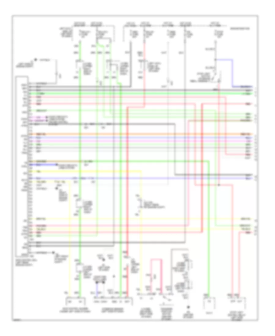
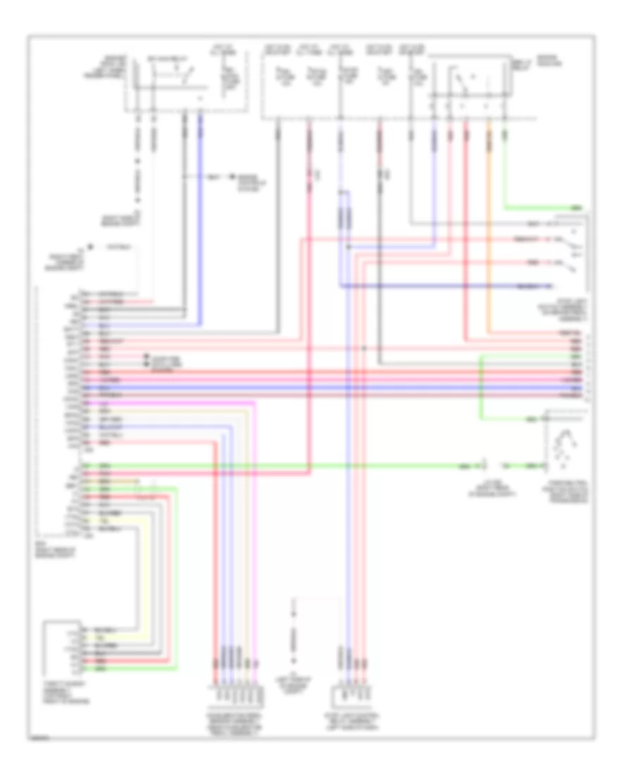
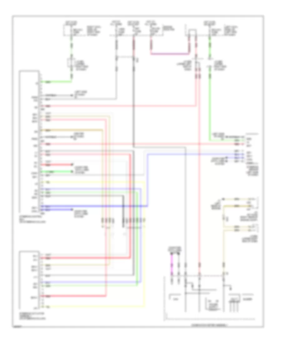
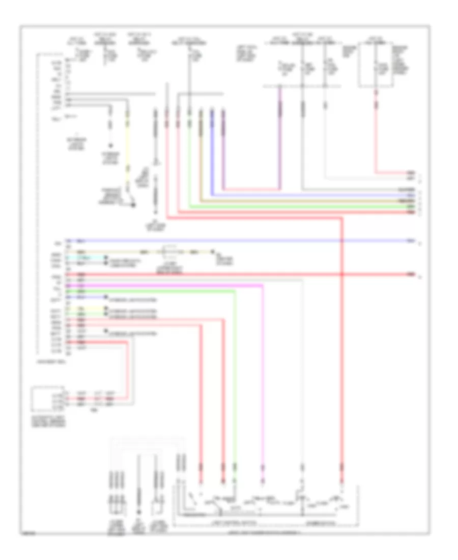
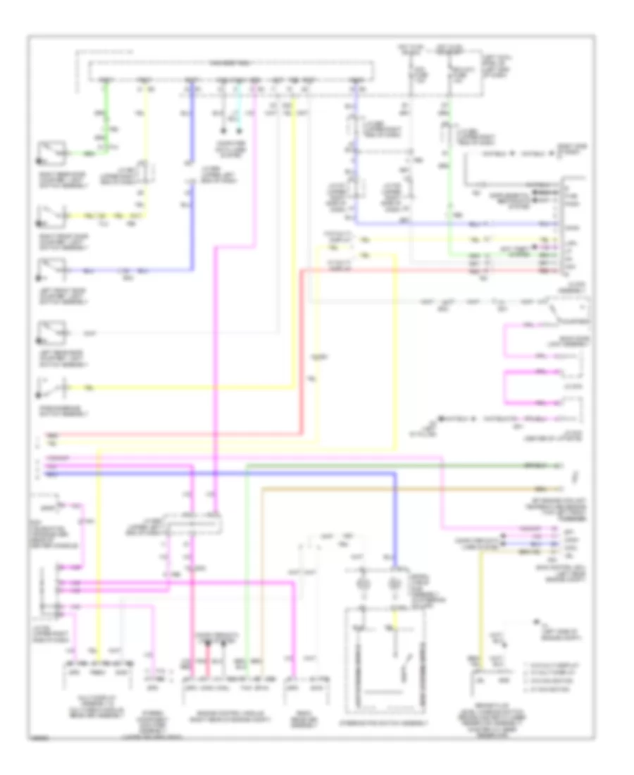
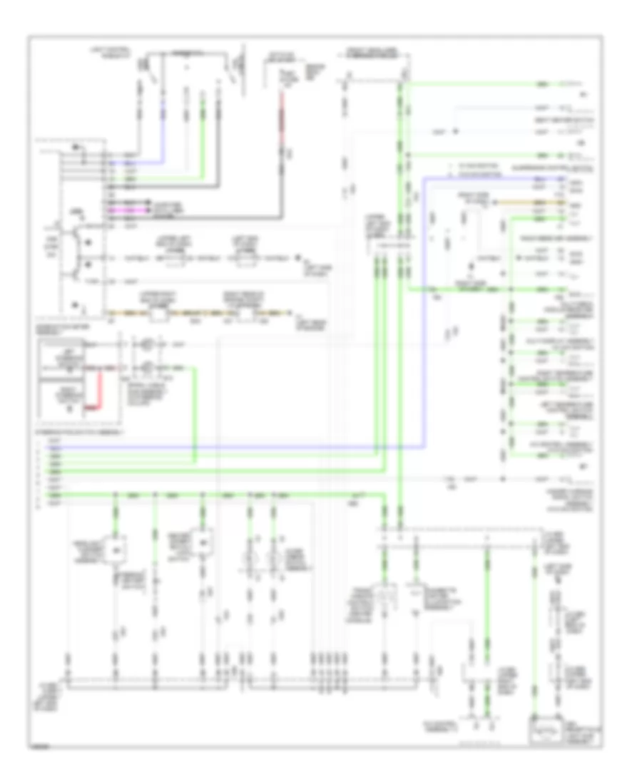
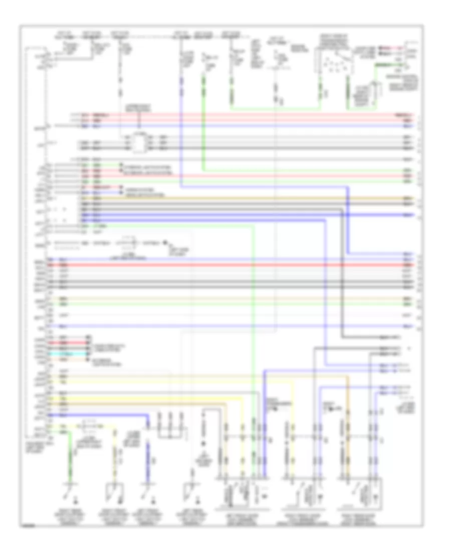
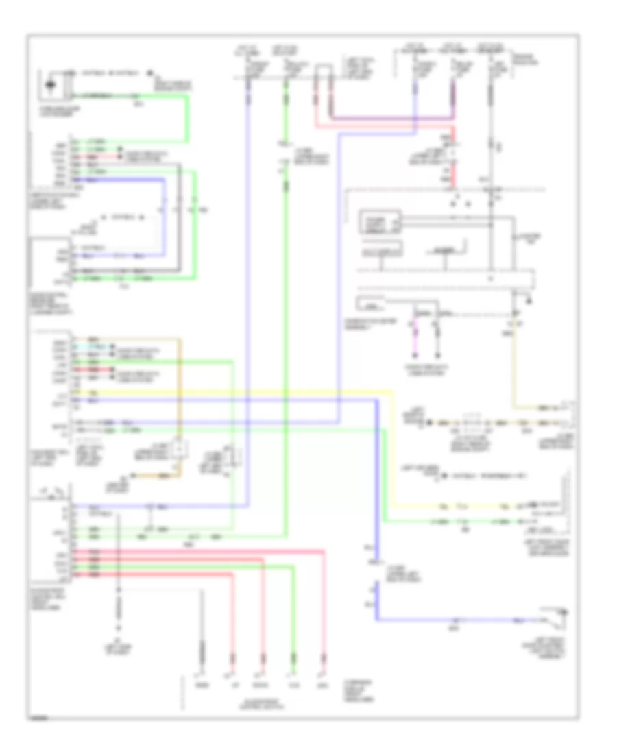
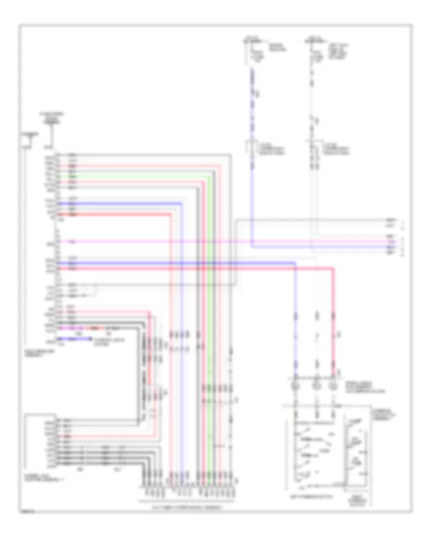
Automatic A/C Wiring Diagram (1 of 4) for Toyota Land Cruiser 2014
 https://portal-diagnostov.com/license.html
Automotive Electricians Portal FZCO
Automotive Electricians Portal FZCO
https://portal-diagnostov.com/license.html
https://portal-diagnostov.com/license.html
Automotive Electricians Portal FZCO
Automotive Electricians Portal FZCO
List of elements for Automatic A/C Wiring Diagram (1 of 4) for Toyota Land Cruiser 2014:
- (center front of engine compt) ambient temperature sensor
- (center of dash) automatic light control sensor
- (left end of dash) j/c e62
- (left end of dash) main body ecu
- (left front of engine compt) a/c pressure sensor
- (left quarterpanel) left rear cooler thermistor 1
- (left side of dash) e1
- (right quarterpanel) right rear cooler thermistor 1
- (right side of dash) e3
- (upper left end of dash) j/c e58
- +b1
- +b2
- A/c amplifier (center of dash)
- A/c control assembly 2
- Ac1
- Act
- Ad1
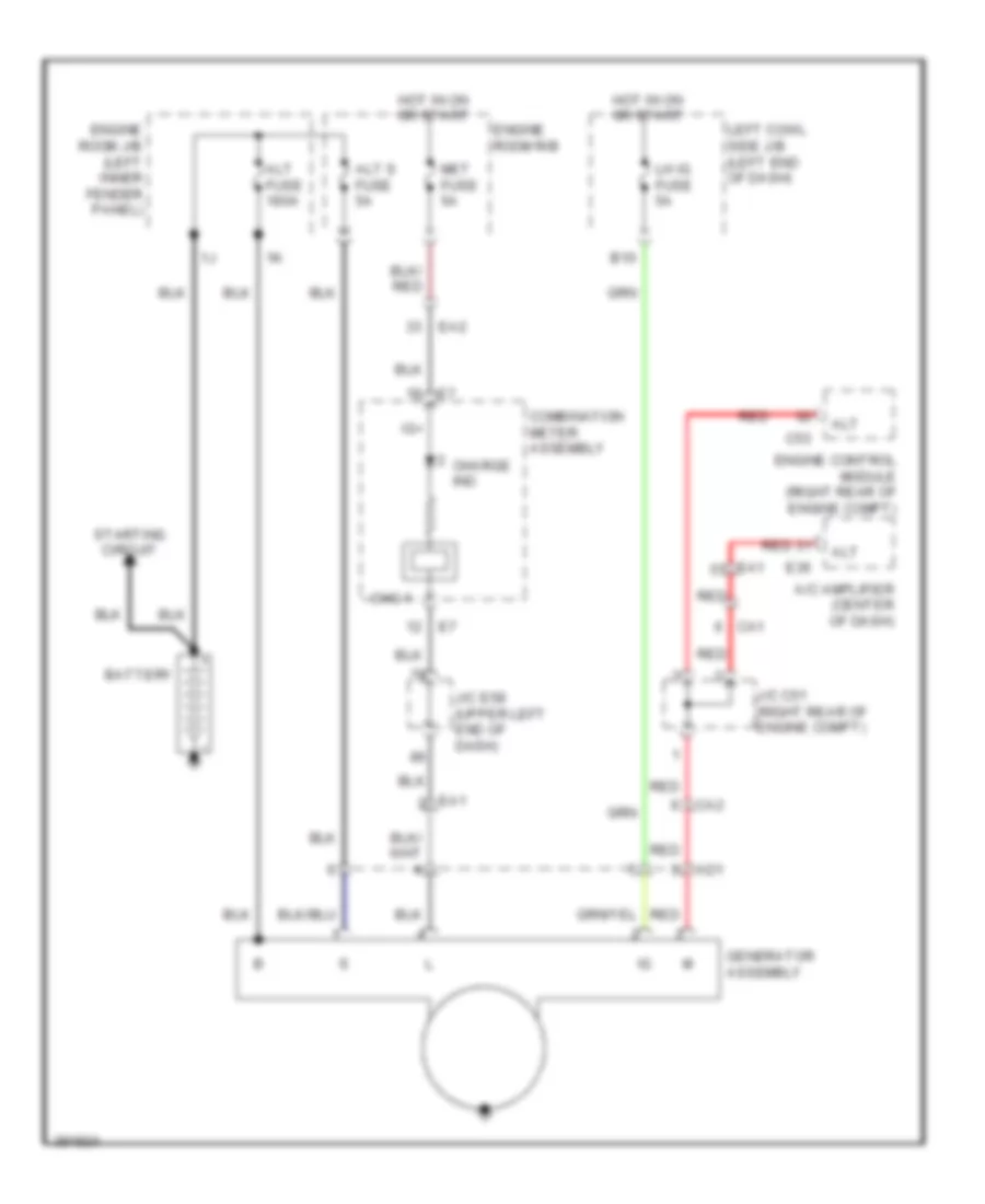
- Alt
- Blw
- Blwh
- Ca1
- Ca2
- Canh
- Canl
- Cfn+
- Cltb
- Clte
- Coli
- Com
- Computer data lines system
- Cool
- Cooling box assembly
- Defogger system
- E3 (right side of dash)
- E35
- E36
- Ea1
- Ea2
- Ea3
- Ek1
- Ek2
- El1
- Fdef
- Fe4
- Fe6
- Generator assembly
- Gnd
- Ig+
- Ill+
- Ill-
- Interior
- Interior lights
- J/c c51 (right rear of engine compt)
- J/c e59 (upper left end of dash)
- Kz2
- Kz5
- Left cooler thermistor (under left rear seat)
- Lights system
- Lin1
- Lock
- Mgc
- Pnk
- Pre
- Ptc1
- Ptc2
- Ptc3
- Rbbu
- Rbug
- Rbus
- Rdef
- Rear seat heater switch & rear a/c control switch
- Red
- Right cooler thermistor (under right rear seat)
- Rlin
- Rly
- Rmgv
- Room temperature sensor (center left of dash)
- S5-1
- Seats system
- Sg-1
- Sg-2
- Sg-5
- Sg-6
- Sg-9
- Sgnd
- Solar sensor
- System
- Tam
- Tec
- Tr3
- Tr4
- Tr7
- Tsd
- Tsl
- Tsp
- Tsr
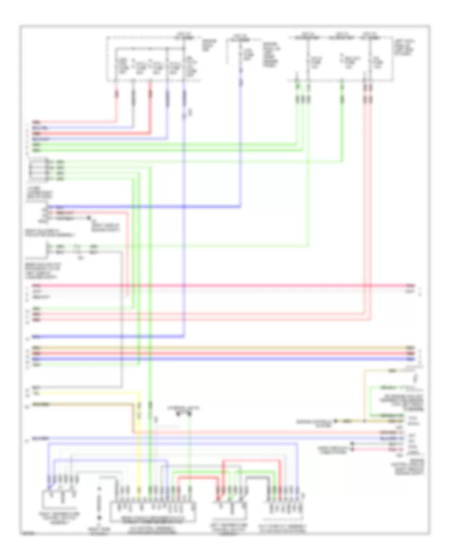
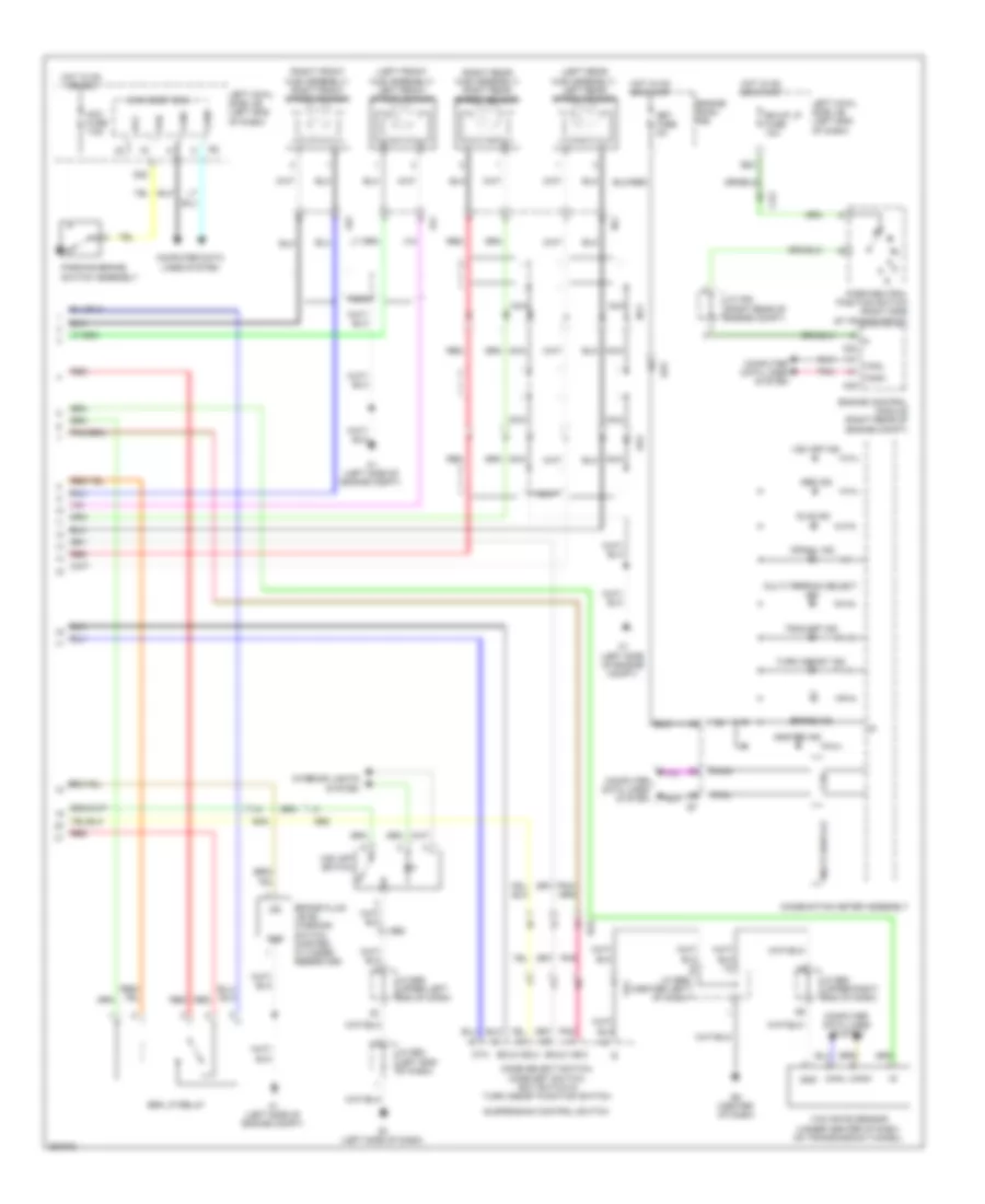
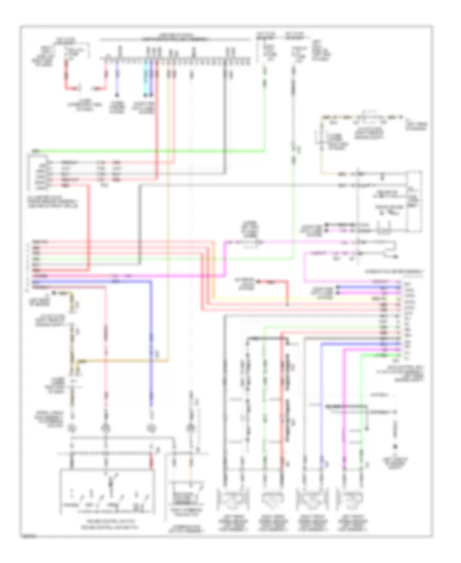
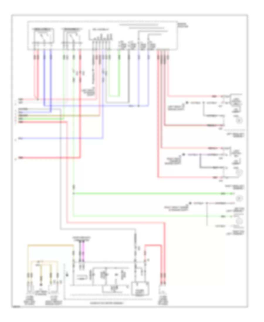
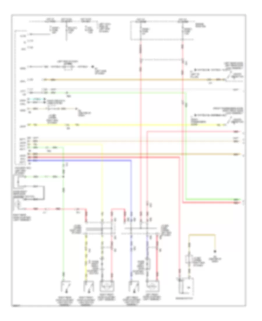
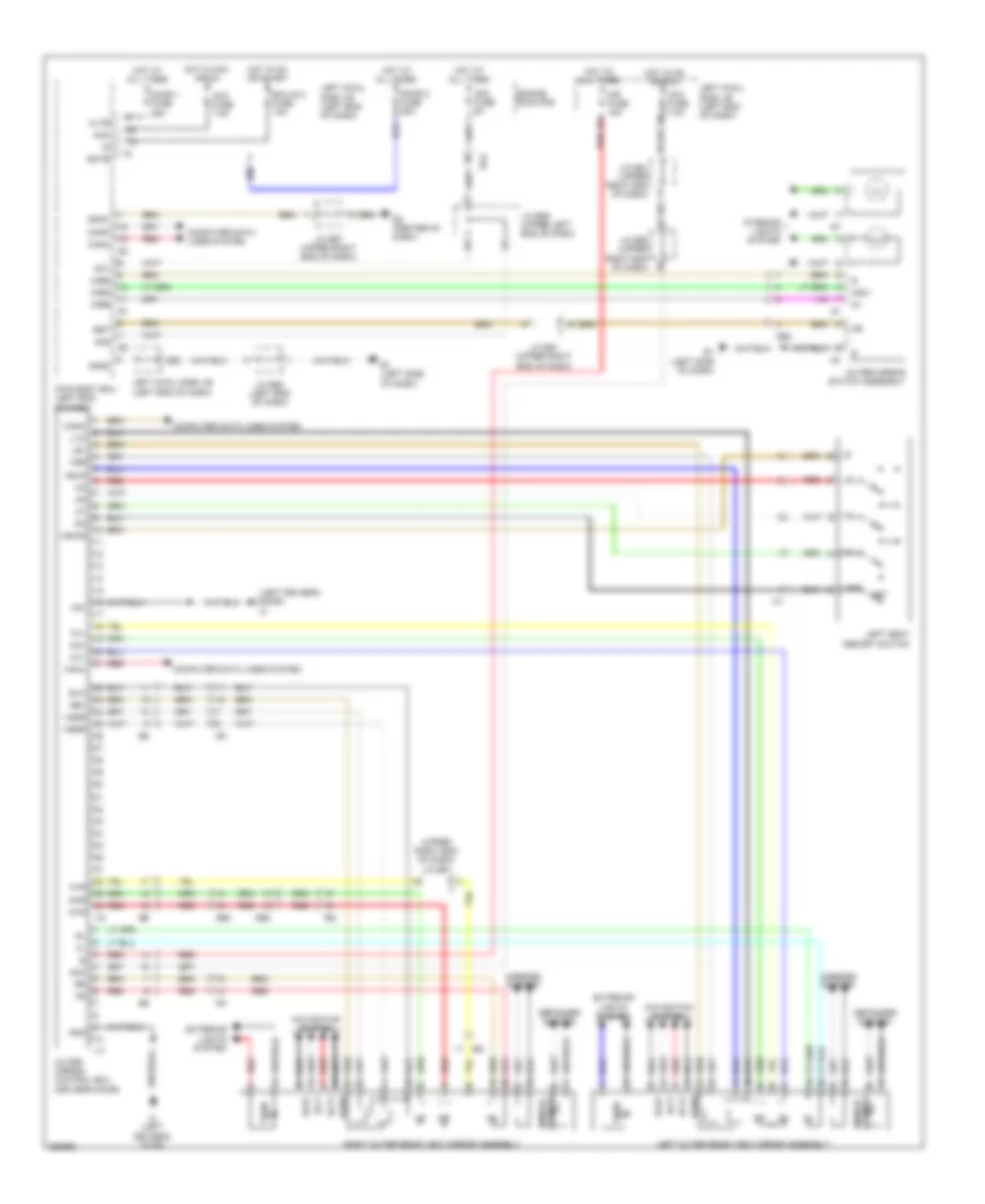
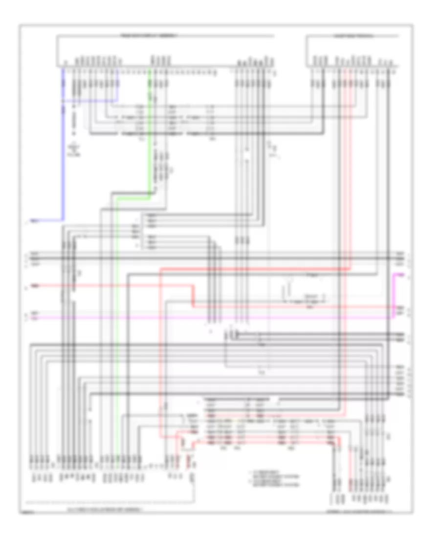
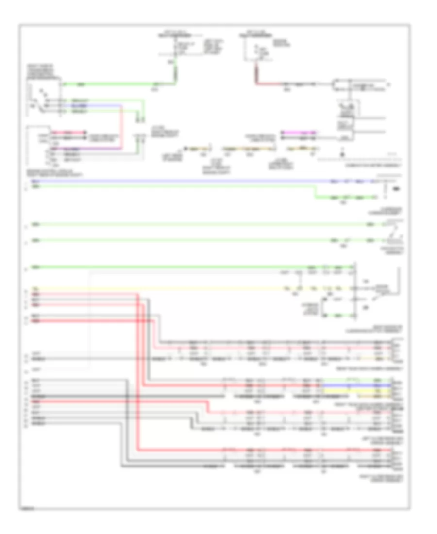
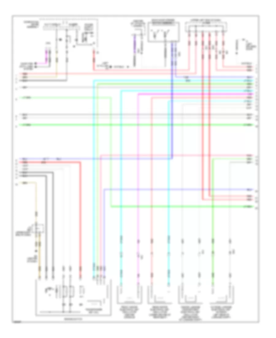
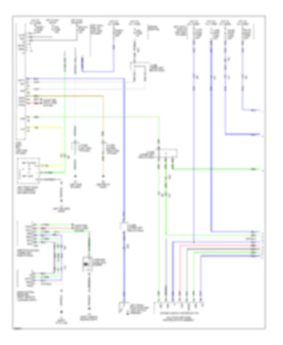
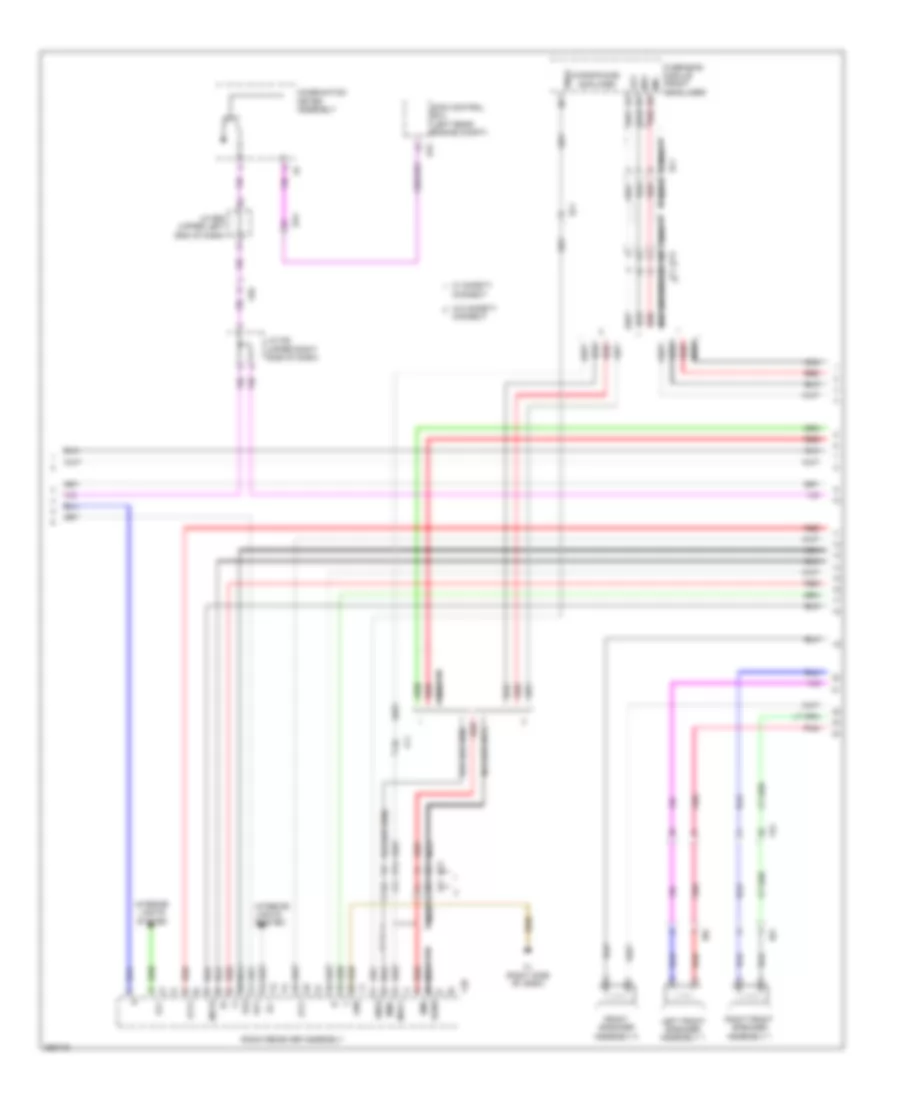
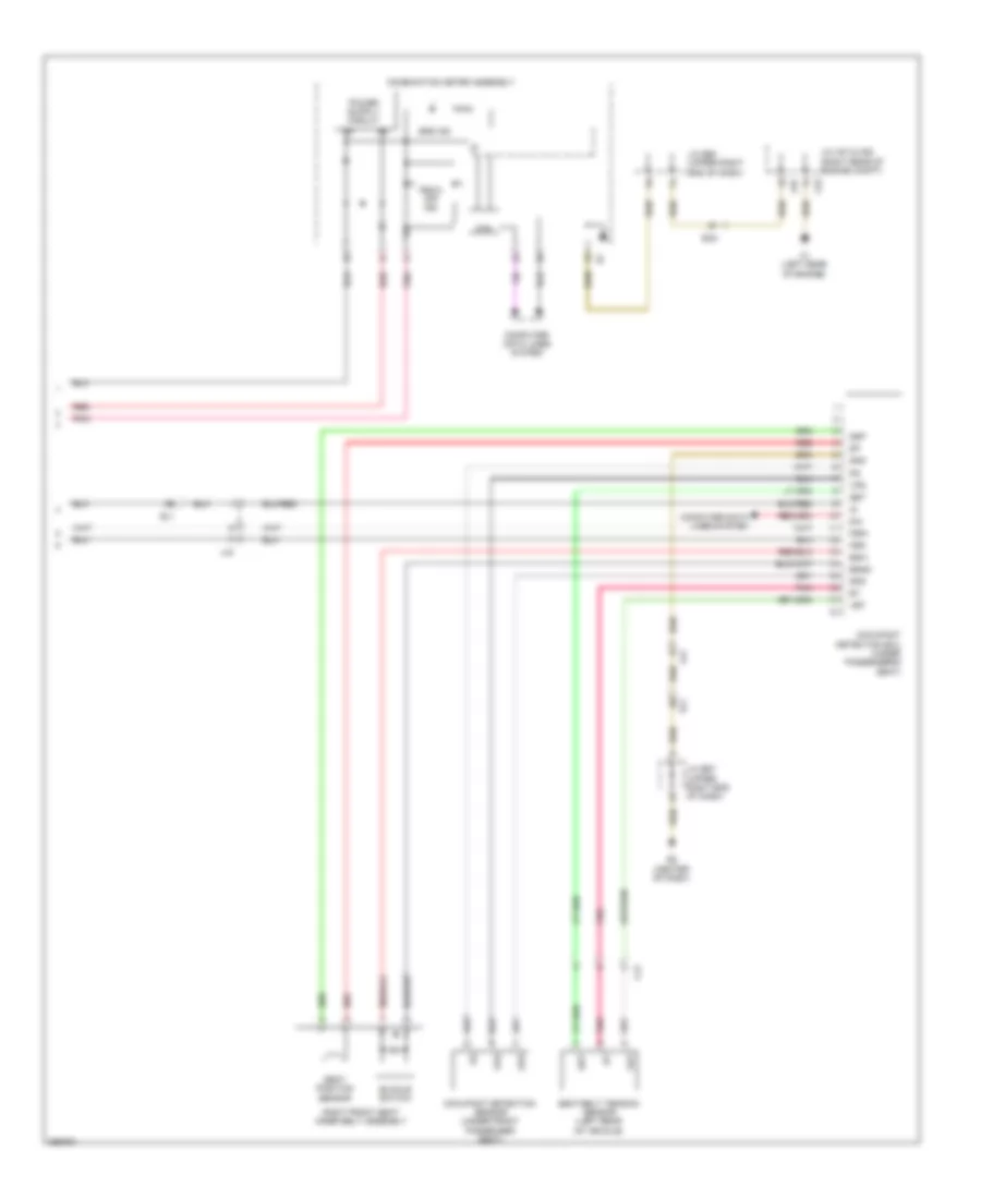
Automatic A/C Wiring Diagram (2 of 4) for Toyota Land Cruiser 2014
List of elements for Automatic A/C Wiring Diagram (2 of 4) for Toyota Land Cruiser 2014:
- A2 (left front of engine compt)
- A3 (right side of engine compt)
- Blower motor control
- Ca2
- Cds fan relay
- Clutch magnetic
- Condenser blower motor (front of engine compt)
- Cooler compressor assembly
- E3 (right side of dash)
- E33
- E34
- Ea2
- Engine room r/b
- Gnd
- K2 (left "d" pillar)
- Kz1
- Lock sensor
- Mg clt relay
- Mg+
- Pnk
- Ptc htr1 relay
- Ptc htr2 relay
- Ptc htr3 relay
- Quick heater assembly
- Rear blower w/ fan motor sub assembly
- Red
- Ssr+
- Ssr-
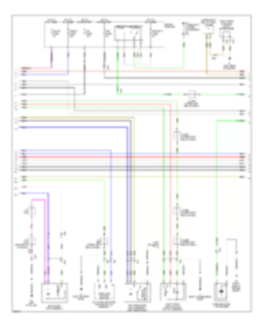
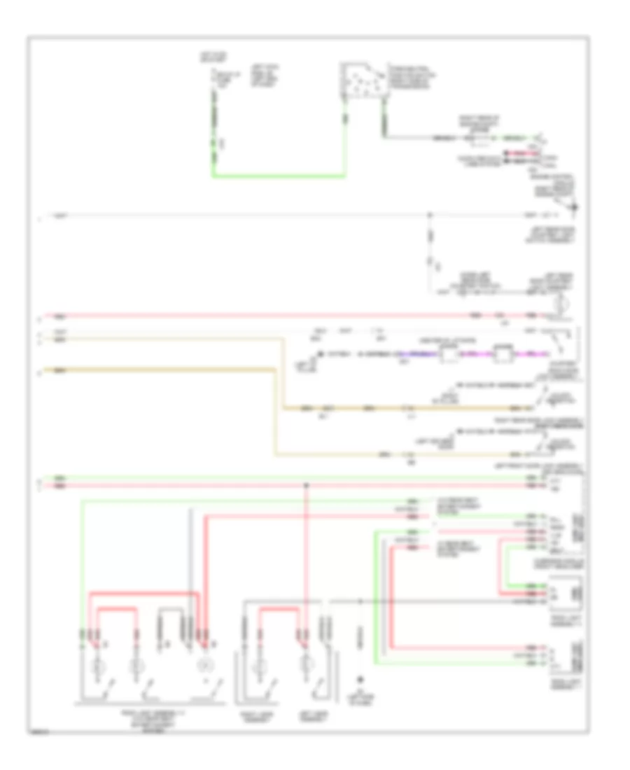
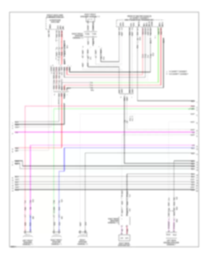
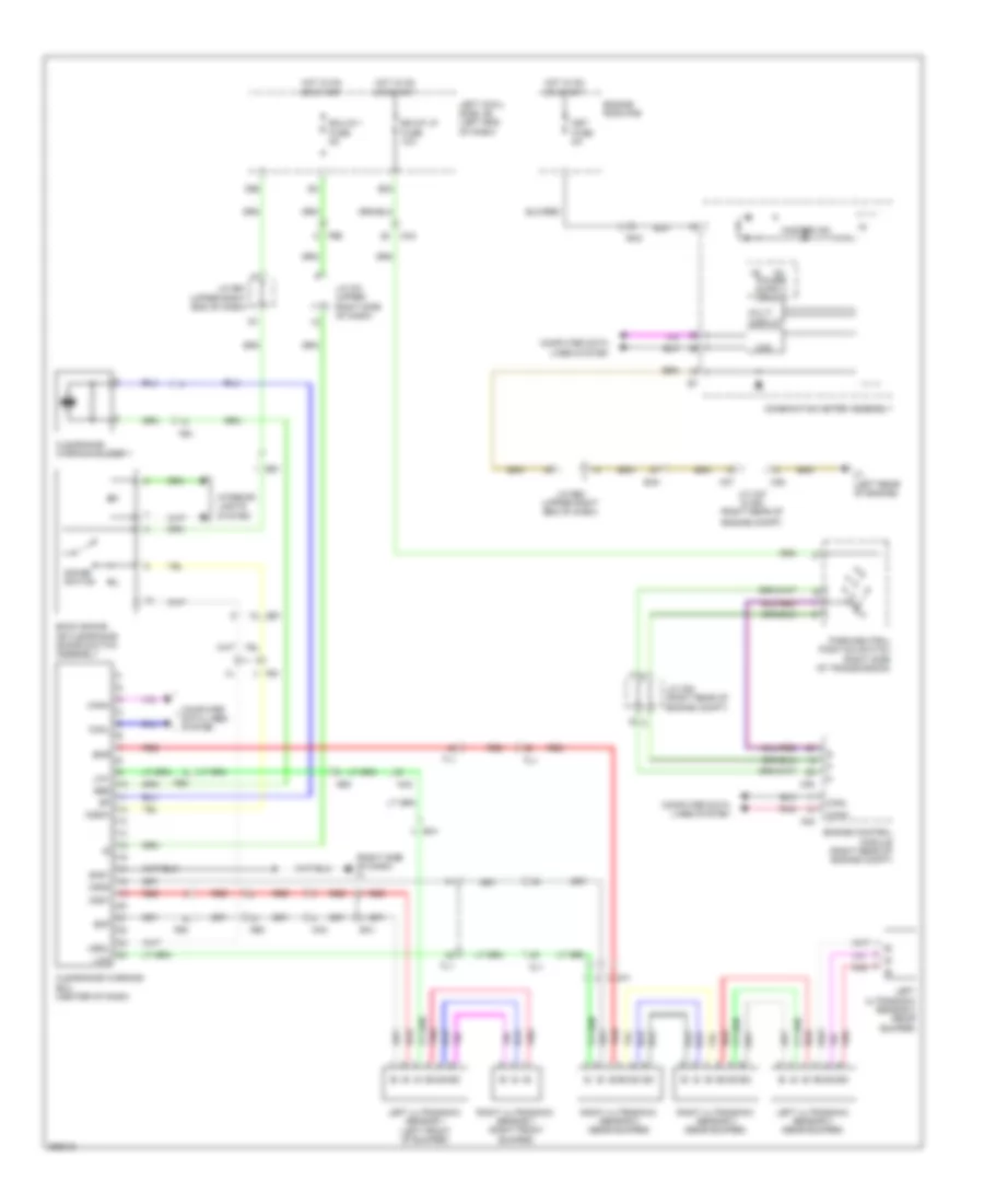
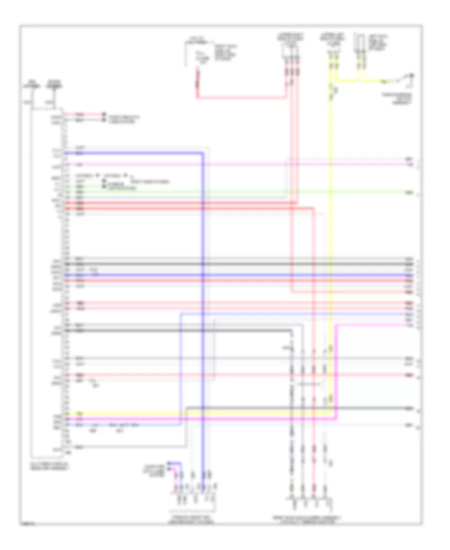
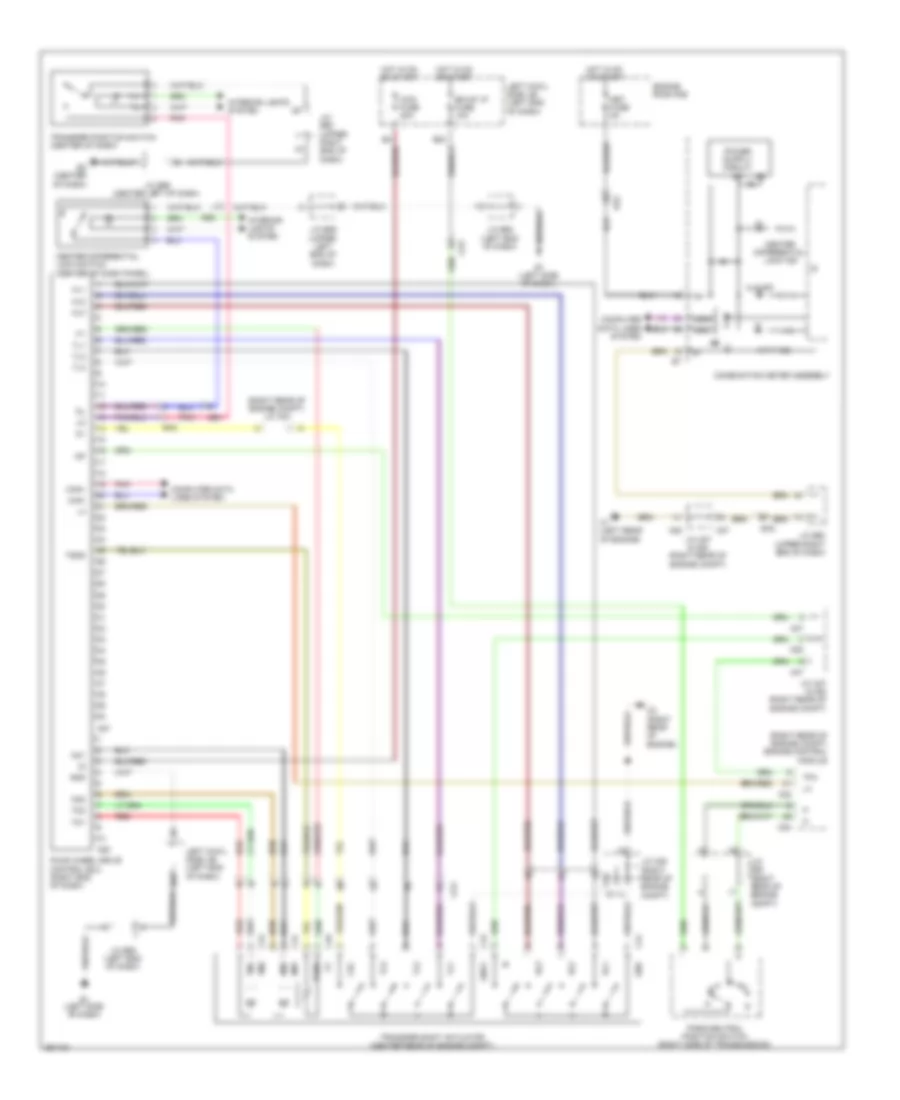
Automatic A/C Wiring Diagram (3 of 4) for Toyota Land Cruiser 2014
List of elements for Automatic A/C Wiring Diagram (3 of 4) for Toyota Land Cruiser 2014:
- A/c control assembly (w/o navigation system)
- A/c fuse 7.5a
- A/c ig fuse 10a
- A3 (right side of engine compt)
- A38
- Ac1
- Act
- Agnd
- Ak3
- Bgnd
- C16
- C53
- Canh
- Canl
- Cds fan fuse 25a
- Computer data lines system
- D58
- D59
- Down
- Dtp+
- Dtp-
- Ecu-ig 2 fuse 10a
- Efi engine coolant temperature sensor (top left front of engine)
- Engine control module (right rear of engine compt)
- Engine controls system
- Engine room j/b (left inner fender panel)
- Engine room r/b
- Ethw
- F1 (right side of dash)
- F46
- Fe4
- Front blower w/ fan motor sub-assembly
- Gnd
- Hot at all times
- Hot in on or start
- Htr fuse 50a
- Ig+
- Ill+
- Ill-
- Interior lights system
- J/c e60 (upper right end of dash)
- Kz1
- Left cowl side j/b (left end of dash)
- Left temperature control switch assembly
- Lin1
- Multi-display assembly (w/ navigation system)
- Pnk
- Ptc 1 fuse 50a
- Ptc 2 fuse 50a
- Ptc 3 fuse 50a
- Ptp+
- Ptp-
- Rear cooling unit expansion valve (left side of luggage compt)
- Rear window defogger switch & front wiper deicer switch
- Red
- Right temperature control switch assembly
- Rr auto a/c fuse 50a
- Tec+
- Tec-
- Tes+
- Tes-
- Thw
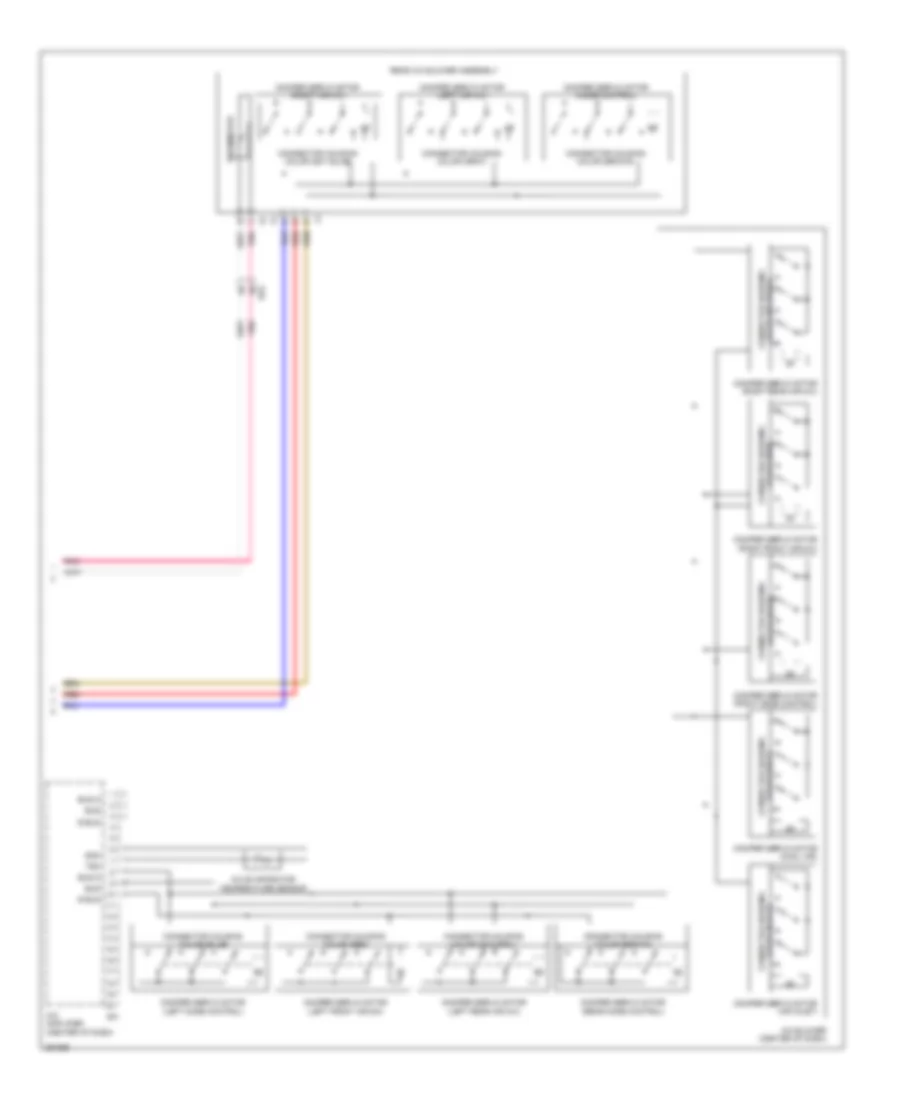
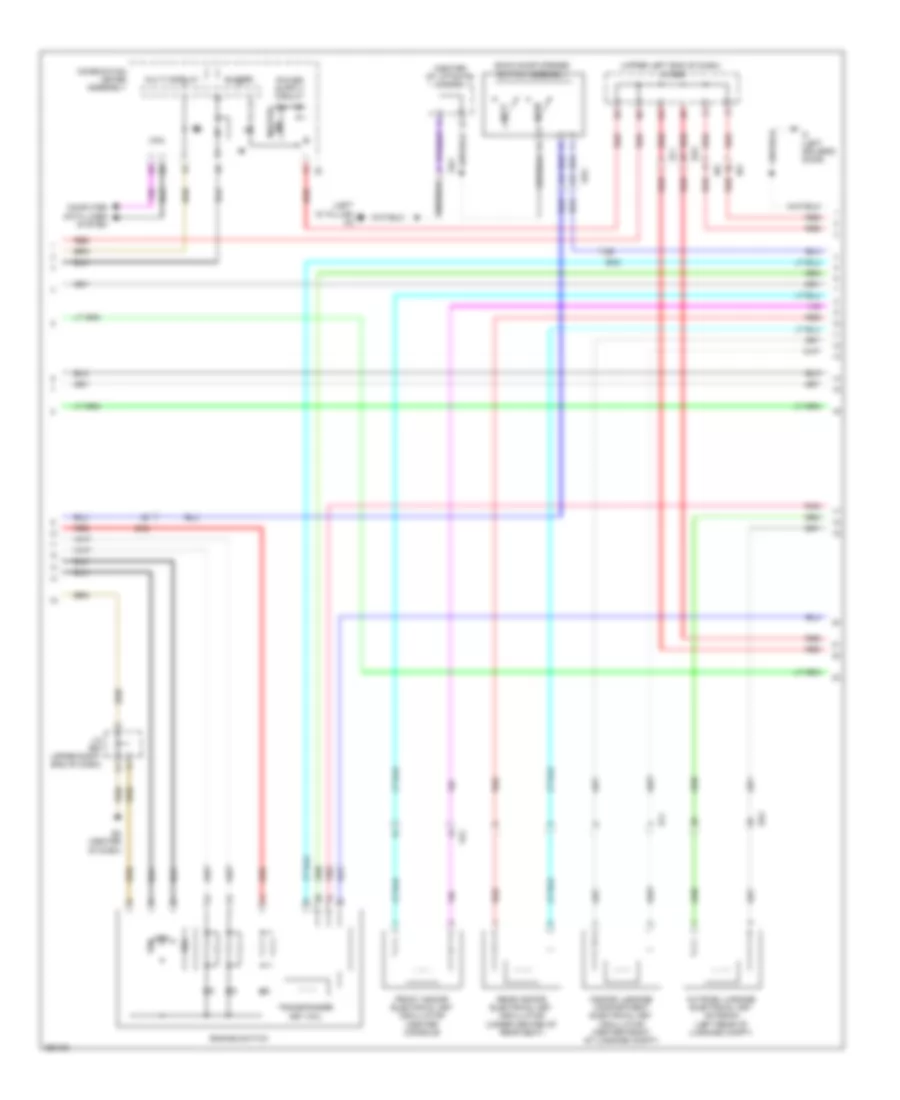
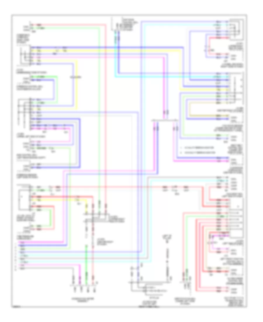
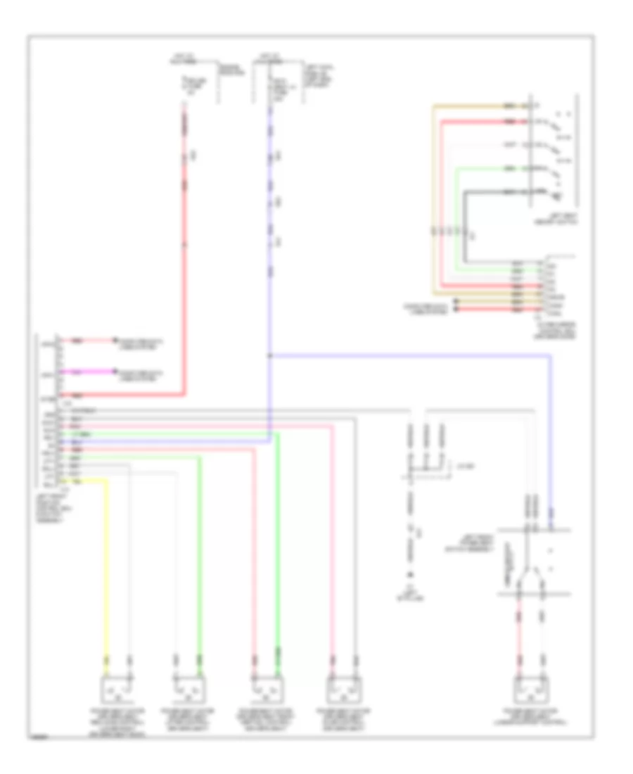
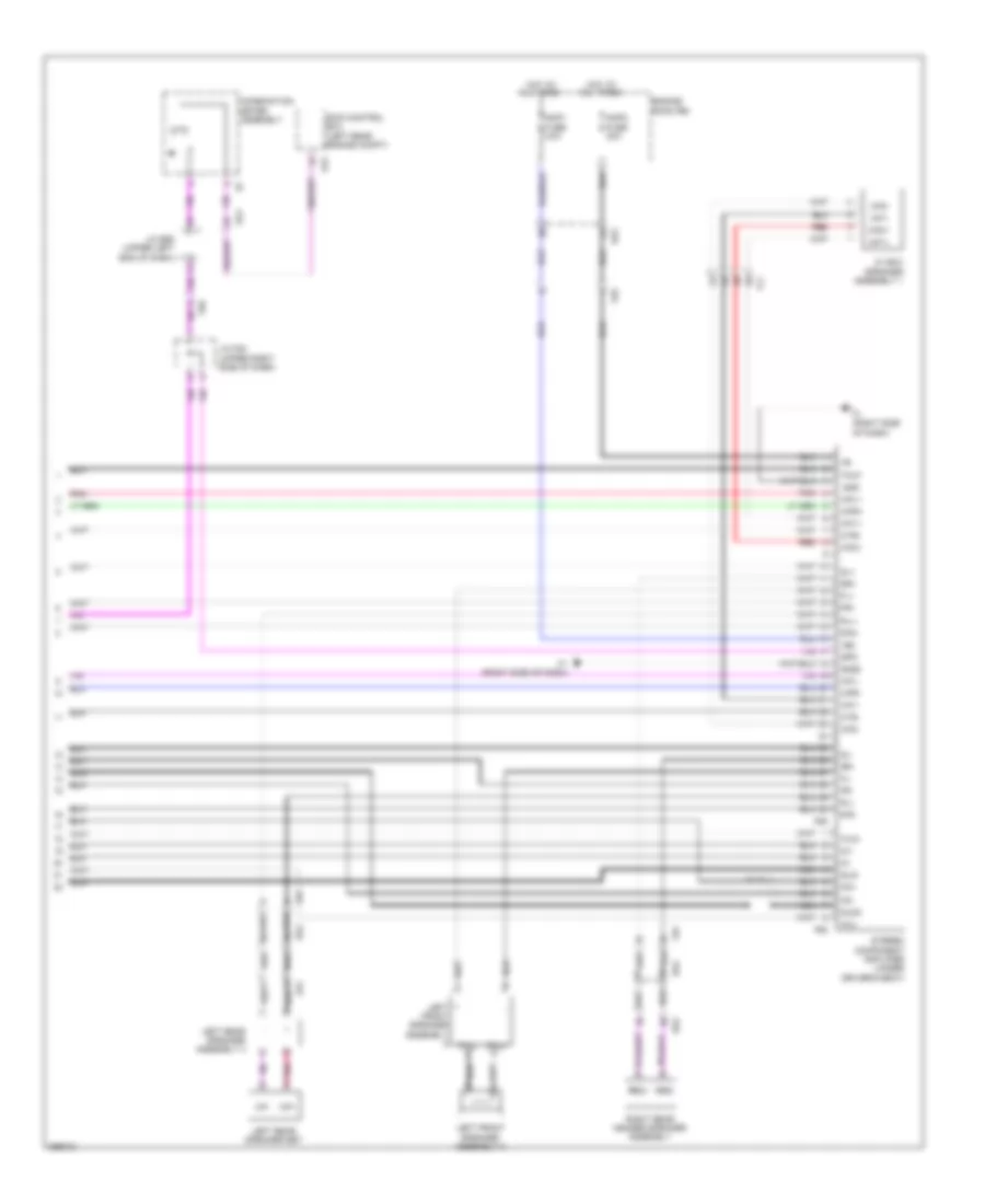
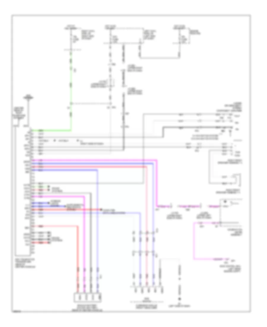
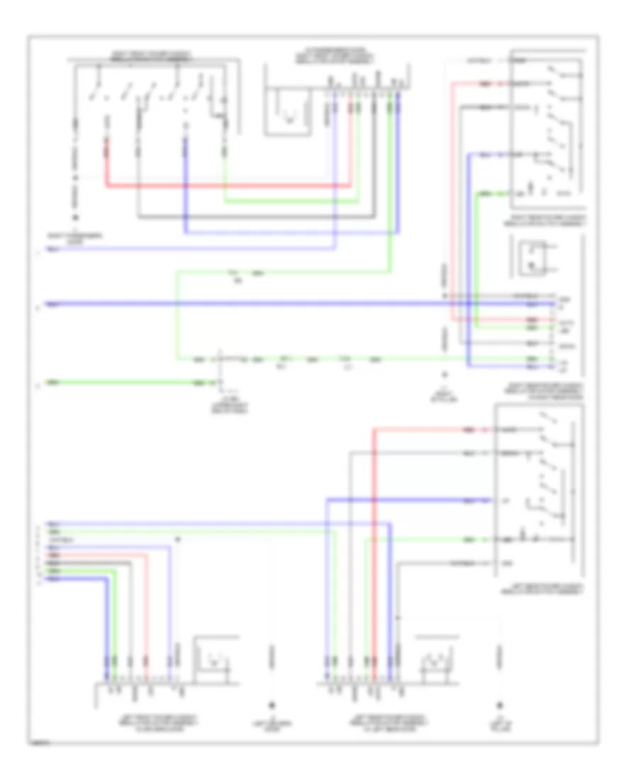
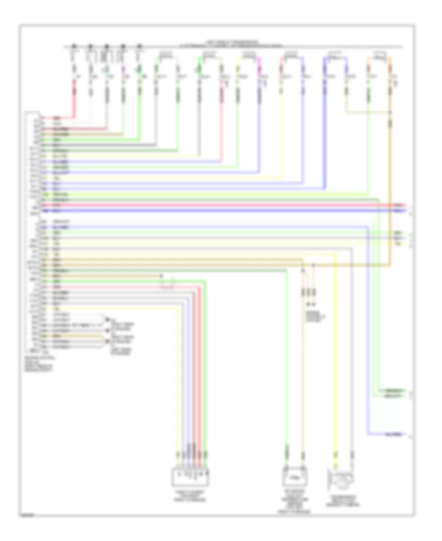
Automatic A/C Wiring Diagram (4 of 4) for Toyota Land Cruiser 2014
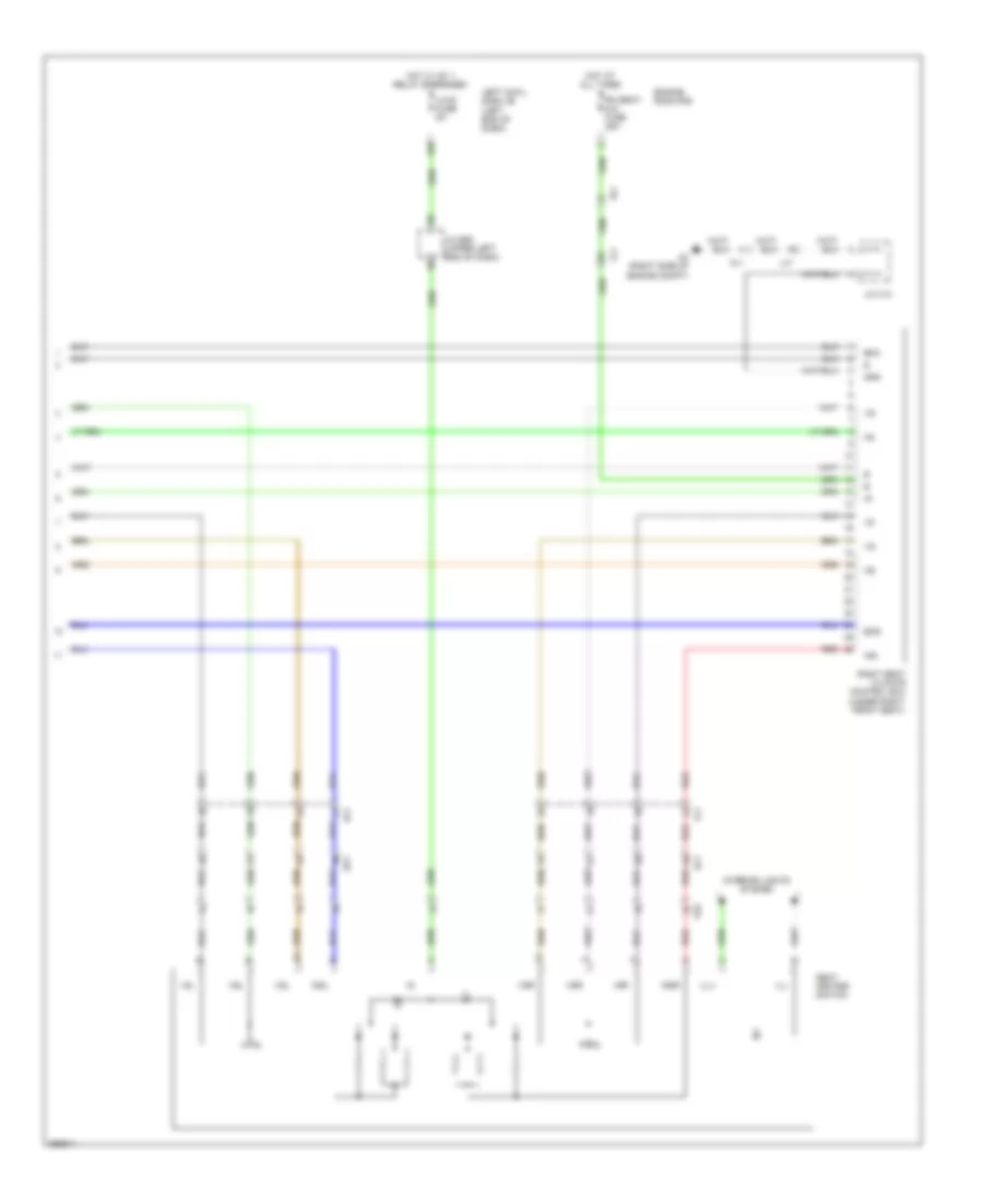
List of elements for Automatic A/C Wiring Diagram (4 of 4) for Toyota Land Cruiser 2014:
- A/c amplifier (center of dash)
- A/c blower (center of dash)
- A/c evaporator temperature sensor
- B bus
- Bus
- Bus g
- Color (black) connector housing
- Color (gray) connector housing
- Color (red)
- Connector housing
- Connector housing color (brown)
- Connector housing color (gray)
- Connector housing color (natural)
- Connector housing color (red)
- Damper servo motor (air inlet)
- Damper servo motor (cool air)
- Damper servo motor (left air mix)
- Damper servo motor (left front air mix)
- Damper servo motor (left mode control)
- Damper servo motor (left rear air mix)
- Damper servo motor (mode control)
- Damper servo motor (rear mode control)
- Damper servo motor (right air mix)
- Damper servo motor (right front air mix)
- Damper servo motor (right mode control)
- Damper servo motor (right rear air mix)
- Ek2
- Pnk
- Rear a/c blower assembly
- Red
- Sga
- Tea
- Thermistor
- Z34
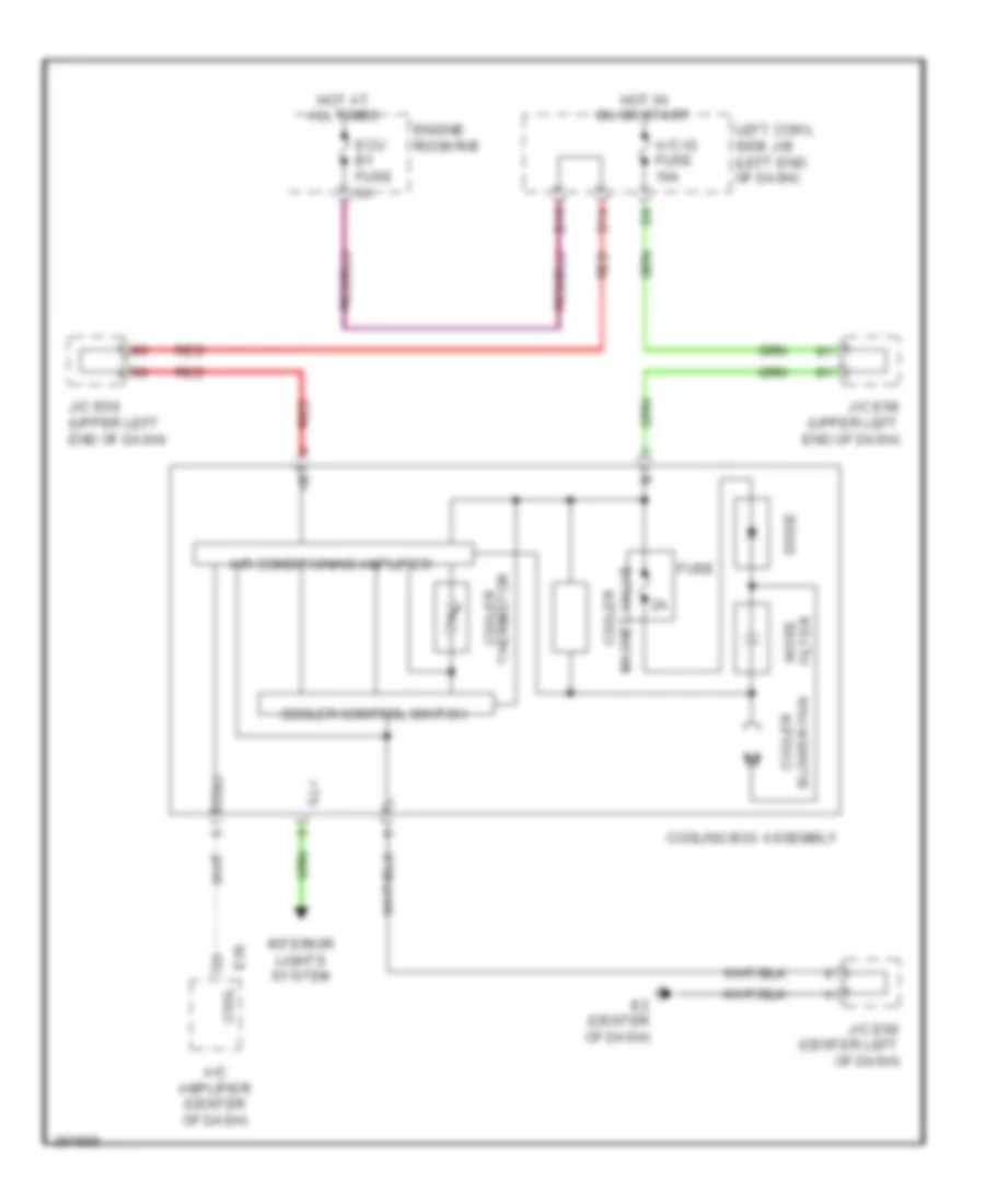
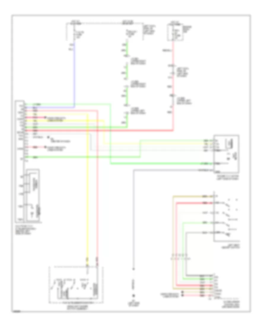
Cool Box Wiring Diagram for Toyota Land Cruiser 2014
List of elements for Cool Box Wiring Diagram for Toyota Land Cruiser 2014:
- A/c amplifier (center of dash)
- A/c ig fuse 10a
- Air conditioning amplifier
- B13
- Blower fan cooler
- Coli
- Cool
- Cooler control switch
- Cooler thermistor
- Cooling box assembly
- D14
- Diode
- E2 (center of dash)
- E36
- Ecu b1 fuse 5a
- Engine room r/b
- Filter noise
- Fuse
- Hot at all times
- Hot in on or start
- Ill+
- Interior lights system
- J/c e58 (upper left end of dash)
- J/c e59 (upper left end of dash)
- J/c e66 (center left of dash)
- Left cowl side j/b (left end of dash)
- Magnet valve cooler
- Red
ANTI-LOCK BRAKES
Anti-lock Brakes Wiring Diagram (1 of 2) for Toyota Land Cruiser 2014
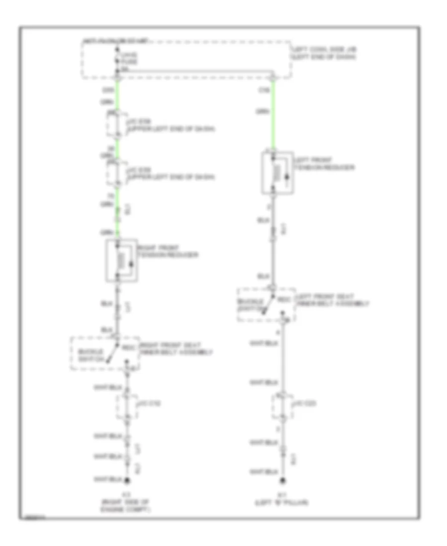
List of elements for Anti-lock Brakes Wiring Diagram (1 of 2) for Toyota Land Cruiser 2014:
- (left front of engine
- (upper left end of dash)
- +bm1
- +bm2
- +bs
- 4 wheel drive ecu (right side of dash)
- A1 (left side of engine compt)
- A24
- A25
- A27
- A3 (right side of engine compt)
- Aa1
- Abs1 fuse 50a
- Abs2 fuse 30a
- Atrc
- B12
- B13
- Bat
- Canh
- Canl
- Compt)
- Computer data lines system
- Computer data lines system cruise control system
- Csw
- D14
- D56
- Dlc 3
- E1 (left side of dash)
- E2 (center of dash)
- Ea1
- Ea2
- Ea3
- Ecu b1 fuse 5a
- Ecu-ig 1 fuse 5a
- Ecu-ig 2 fuse 10a
- Engine room r/b
- Ess
- Ex14
- Exi
- Fl+
- Fl-
- Fr+
- Fr-
- Gnd1
- Gnd2
- Gnd3
- Hot at all times
- Hot in on or start
- Ig1
- Ig2
- Ign fuse 10a
- J/c a34 (right rear of engine compt)
- J/c e59
- J/c e59 (upper left end of dash)
- J/c e60 (upper right end of dash)
- J/c e61 (upper right end of dash)
- J/c e66 (center left of dash)
- Lbl
- Left cowl side j/b (left end of dash)
- Out
- Pnk
- Red
- Rl+
- Rl-
- Rr+
- Rr-
- Skid control buzzer (under left side of dash)
- Skid control ecu (left rear engine compt)
- Sp1
- Steering sensor (left side of dash)
- Stop fuse 15a
- Stop light control relay (left side of dash)
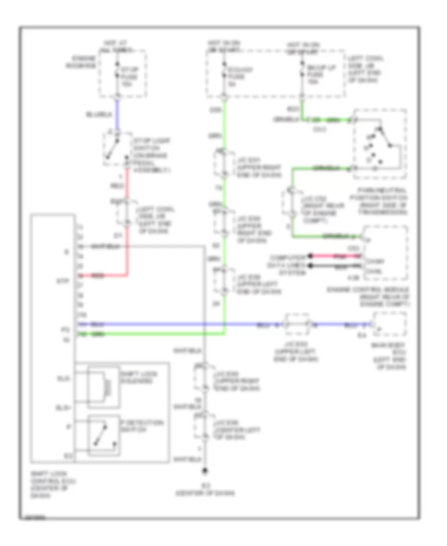
- Stop light switch (on brake pedal assembly)
- Stp
- Stp2
- Stpo
- Transfer position switch (center of dash)
- Trm2
- Trmi
- Trs
- Ve1
Anti-lock Brakes Wiring Diagram (2 of 2) for Toyota Land Cruiser 2014
List of elements for Anti-lock Brakes Wiring Diagram (2 of 2) for Toyota Land Cruiser 2014:
- (left front hub assembly) left front speed sensor
- (left rear hub assembly) left rear speed sensor
- (right front hub assembly) right front speed sensor
- (right rear hub assembly) right rear speed sensor
- A1 (left side of engine compt)
- A38
- Abs ind
- Acc
- Acc fuse 7.5a
- Ak2
- Az1
- Az2
- B23
- Bk/up lp fuse 10a
- Brake fluid level warning switch (master cylinder reservoir)
- Brake ind
- Brk lp relay
- C53
- Ca3
- Can
- Canh
- Canl
- Combination meter assembly
- Computer data lines system
- Crawl ind
- D22
- E1 (left side of dash)
- E2 (center of dash)
- Ea2
- Ecu2
- Ecu3
- Ecui
- Engine control module (right rear of engine compt)
- Engine room r/b
- Ge2
- Gnd
- Hot in on or acc
- Hot in on or start
- Hsw
- Ig+
- Interior lights system
- J/c c52 (right rear of engine compt)
- J/c e59 (upper left end of dash)
- J/c e60 (upper right end of dash)
- J/c e62 (left end of dash)
- J/c e66 (center left of dash)
- Lbl
- Left cowl side j/b (left end of dash)
- Main body ecu
- Master ind
- Met fuse 5a
- Mode select switch, mode set switch, ect switch & turn assist function switch
- Multi display
- Multi-terrain select ind
- Nca
- Nk1
- Nz1
- Ota
- Park/neutral position switch (right side of transmission)
- Parking brake switch assembly
- Pkb
- Pnk
- Red
- Slip ind
- Suspension control switch
- Trac off ind
- Turn assist ind
- Ve1
- Vsc off ind
- Vsc off switch
- Yaw rate sensor (under center of dash, on transmission tunnel)
ANTI-THEFT
Forced Entry Wiring Diagram (1 of 4) for Toyota Land Cruiser 2014
List of elements for Forced Entry Wiring Diagram (1 of 4) for Toyota Land Cruiser 2014:
- (right "b" pillar) l1
- (right passenger's door) i1
- (right side of transmission) park/neutral position switch
- (upper right end of dash)
- A38
- Acc
- Acc fuse 7.5a
- Act+
- Act-
- Actd
- Altb
- Am1
- Am2
- Am2 fuse 5a
- B13
- B15
- B18
- B20
- B22
- B23
- Batb
- Bcty
- Bdsu
- Bk/up lp fuse 10a
- C23
- C24
- C53
- Ca3
- Canh
- Canl
- Cann
- Canp
- Computer data lines system
- D14
- D17
- D20
- D32
- D49
- D51
- D52
- D53
- D56
- D62
- Dcty
- Detection unlock
- Door 1 fuse 25a
- E1 (left side of dash)
- Ea2
- Ecu ig 2 fuse 10a
- Ecu ig fuse 5a
- Ek2
- El1
- Engine control module (right rear of engine compt)
- Engine room r/b
- Exterior lights system
- Fe3
- Fe4
- Fl2
- Gnd2
- Gnd3
- Haz
- Headlights system
- Horn
- Horns system
- Hot at all times
- Hot in on or acc
- Hot in on or start
- Hrly
- I2 (left driver's door)
- Ie3
- Ie6
- Ile
- Inds
- Indw
- Interior lights system
- J/c c52 (right rear of engine compt)
- J/c e59 (upper left end of dash)
- J/c e61
- J/c e61 (upper right end of dash)
- J/c e62 (left end of dash)
- J/c e89 (left end of dash)
- Jl1
- Key lock
- Key unlock
- Lcty
- Left cowl side j/b (left end of dash)
- Left front door courtesy light switch assembly
- Left front door lock assembly (driver's door)
- Left rear door courtesy light switch assembly
- Lh fr door fuse 20a
- Lin1
- Lin2
- Lswd
- Lswl
- Lswp
- Lswr
- Main body ecu (left end of dash)
- Pcty
- Pnk
- Rcty
- Red
- Right front door courtesy light switch assembly
- Right front door lock assembly (front passenger's door)
- Right rear door courtesy light switch assembly
- Right rear door lock assembly (right rear door)
- Ssw1
- Ssw2
- Stp
- Swil
- Tr+
- Ul1
- Ul3
- Unlock detection
Forced Entry Wiring Diagram (2 of 4) for Toyota Land Cruiser 2014
List of elements for Forced Entry Wiring Diagram (2 of 4) for Toyota Land Cruiser 2014:
- (left "b" pillar) k1
- (right rear of engine compt) j/c a37 & c52
- (upper right end of dash) j/c e60
- A3 (right side of engine compt)
- A37
- Back door lock assembly
- C1 (left rear of engine)
- C52
- Courtesy
- Detection unlock
- Door 2 fuse 25a
- Door lock control switch
- Ea1
- Ea2
- Ea3
- Ecu b1 fuse 5a
- Ek2
- Engine room r/b
- Gnd
- Hot at all times
- Hot in on or start
- I1 (right passenger's door)
- I2 (left driver's door)
- Ie3
- Ie5
- Ie6
- Ign fuse 10a
- J/c e58 (upper left end of dash)
- J/c e59 (upper left end of dash)
- J/c e60 (upper right end of dash)
- J/c e61 (upper right end of dash)
- J/c s15 (center of liftgate)
- J/c s16
- Jk1
- K2 (left "d" pillar)
- Left rear door lock assembly (left rear door)
- Lin1
- Lock
- Met fuse 5a
- Multiplex network master switch assembly
- Red
- Right front door control switch assembly
- Security fuse 5a
- Security horn assembly
- Security horn relay
- Sk1
- Unlock
- Wireless door lock buzzer
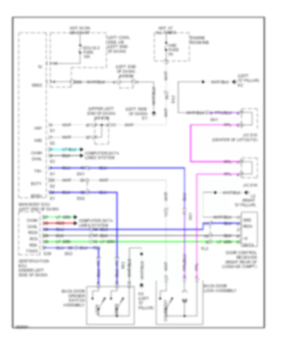
Forced Entry Wiring Diagram (3 of 4) for Toyota Land Cruiser 2014
List of elements for Forced Entry Wiring Diagram (3 of 4) for Toyota Land Cruiser 2014:
- (center of liftgate) j/c s15
- (left "d" pillar) k2
- (upper left end of dash)
- Back door opener switch assembly
- Buzzer
- Can
- Combination meter assembly
- Computer data lines system
- E2 (center of dash)
- Ek2
- El1
- Engine switch
- Front indoor electrical key oscillator (center console)
- Gnd
- I2 (left driver's door)
- Ie2
- Ie5
- Ig+
- Ind
- Indoor luggage compartment electrical key oscillator (center front of luggage compt)
- J/c e59
- J/c e67 (upper right end of dash)
- Lock
- Master
- Multi display
- Open
- Outside luggage electrical key antenna (left rear of luggage compt)
- Pnk
- Rear indoor electrical key oscillator (under center of rear seat)
- Red
- Sk1
- Sk2
- Ss1
- Ss2
- Transponder key coil
- Ve1
Forced Entry Wiring Diagram (4 of 4) for Toyota Land Cruiser 2014
List of elements for Forced Entry Wiring Diagram (4 of 4) for Toyota Land Cruiser 2014:
- (center front of engine compt)
- (right passenger's door) i1
- (right side of dash)
- (upper right end of dash) j/c e61
- A4 (right front corner of engine compt)
- Acc
- Agnd
- Ant1
- Ant2
- Bzr
- Canh
- Canl
- Certification ecu (under left side of dash)
- Cg1b
- Cg2b
- Cg3b
- Cg4b
- Cg5b
- Cg6b
- Cg7b
- Cg8b
- Clg
- Clg1
- Clg2
- Clg3
- Clg4
- Clg5
- Clg6
- Clg7
- Clg8
- Clgb
- Clock assembly
- Code
- Computer data lines system
- Data
- Door control receiver (right rear of luggage compt)
- E1 (left side of dash)
- E29
- E30
- Ea1
- Ek2
- El1
- Engine hood courtesy switch
- Engine room r/b
- F60
- Fe3
- Fe5
- Fl2
- Fg1
- Gnd
- Gnd1
- Hot at all times
- Hsw
- Ie2
- Ie5
- Imb fuse 7.5a
- Ind
- J/c e62 (left end of dash)
- Jk1
- Jl1
- K1 (left "b" pillar)
- L1 (right "b" pillar)
- L2 (right "d" pillar)
- Left front door electrical key oscillator
- Left front door outside handle assembly
- Left rear door electrical key oscillator
- Left rear door outside handle assembly
- Lin
- Mult- display assembly
- Pnk
- Rc0
- Rda
- Red
- Right front door electrical key oscillator
- Right front door outside handle assembly
- Right rear door electrical key oscillator
- Right rear door outside handle assembly
- Rssi
- Sec
- Security ind
- Sel
- Sel1
- Sel2
- Sel3
- Sel4
- Sen1
- Sen2
- Sen3
- Sen4
- Sens
- Sgt
- Sh-
- Trg+
- Trg-
- Tsw1
- Tsw2
- Tsw3
- Tsw4
- Tsw5
- Txct
- Vc5
- W/ navigation
- W/o navigation
- Zi1
- Zi2
- Zj1
- Zj2
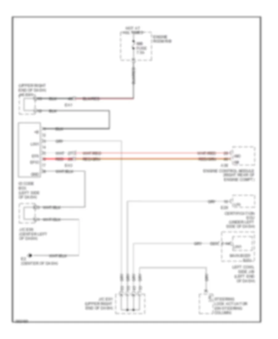
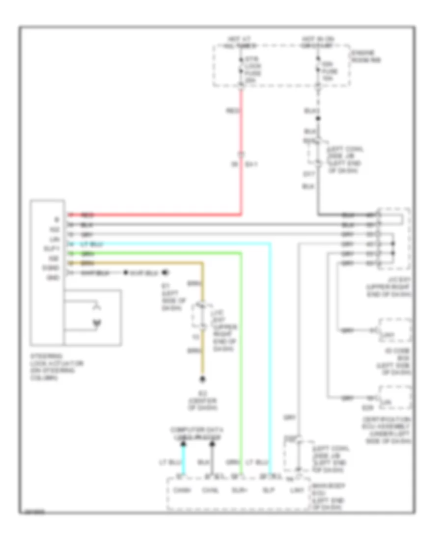
Immobilizer Wiring Diagram for Toyota Land Cruiser 2014
List of elements for Immobilizer Wiring Diagram for Toyota Land Cruiser 2014:
- (upper right end of dash) j/c e61
- A38
- Certification ecu (under left side of dash)
- D20
- E2 (center of dash)
- E29
- Ea1
- Ea3
- Efii
- Efio
- Engine control module (right rear of engine compt)
- Engine room r/b
- Gnd
- Hot at all times
- Id code box (left side of dash)
- Imb fuse 7.5a
- Imi
- Imo
- J/c e61 (upper right end of dash)
- J/c e66 (center left of dash)
- Left cowl side j/b (left end of dash)
- Lin
- Lin1
- Main body ecu
- Red
- Steering lock actuator (on steering column)
BODY CONTROL MODULES
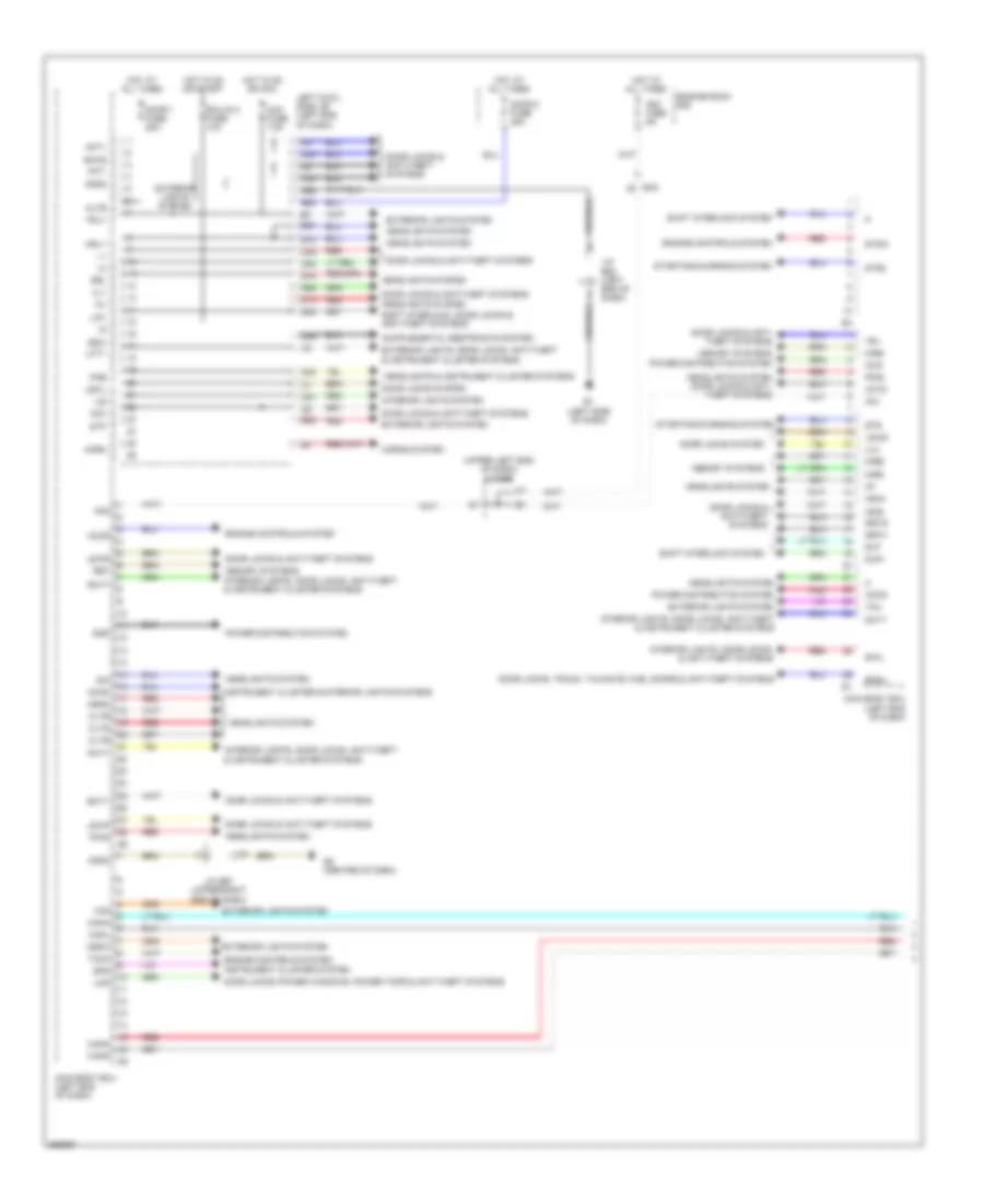
Body Control Modules Wiring Diagram (1 of 2) for Toyota Land Cruiser 2014
List of elements for Body Control Modules Wiring Diagram (1 of 2) for Toyota Land Cruiser 2014:
- (upper left end of dash) j/c e59
- Acan
- Acc
- Acc fuse 7.5a
- Accd
- Accr
- Act+
- Act-
- Actd
- Altb
- Am1
- Am2
- Am2 fuse 5a
- B16
- B18
- B20
- B22
- Batb
- Bcty
- Bdsu
- C23
- C24
- Canh
- Canl
- Cann
- Canp
- Cltb
- Clte
- Clts
- D13
- D20
- D22
- D23
- D25
- D49
- D51
- D52
- D53
- D62
- Dcty
- Dim
- Door 1 fuse 25a
- Door 2 fuse 25a
- Door locks & anti- theft systems
- Door locks & anti-theft systems
- Door locks system
- Door locks, power windows, power tops & anti-theft systems
- Door locks, trunk, tailgate, fuel doors & anti-theft systems
- Drl
- E1 (left side of dash)
- E2 (center of dash)
- Ea2
- Ecu-ig 2 fuse 10a
- Engine controls system
- Engine room r/b
- Exterior lights system
- Exterior lights, door locks, anti-theft & instrument cluster systems
- Ffgo
- Ffog
- Gnd2
- Gnd3
- Gsw
- Haz
- Head
- Headlights & instrument cluster systems
- Headlights system
- Headlights system door locks & anti- theft systems
- Horn
- Horns system
- Hot at all times
- Hot in on or acc
- Hot in on or start
- Hrly
- Hzsw
- Ig1d
- Ig2d
- Ile
- Inds
- Indw
- Instrument cluster & interior lights systems
- Instrument cluster system
- Interior lights system
- Interior lights, door locks, & anti-theft systems
- Interior lights, door locks, anti-theft & instrument cluster systems
- J/c e62 (left end of dash)
- J/c e67 (upper right end of dash)
- Lcty
- Left cowl side j/b (left end of dash)
- Lin1
- Lin2
- Lswd
- Lswl
- Lswp
- Lswr
- Main body ecu (left end of dash)
- Memory systems
- Mirb
- Mire
- Mirs
- Pcty
- Pkb
- Pnk
- Power distribution system
- Rcty
- Red
- Ret
- Shift interlock system
- Shift interlock, door locks & anti-theft systems
- Slp
- Slr+
- Spd
- Ssw1
- Ssw2
- Starting/charging system
- Stp
- Str
- Str2
- Stsw
- Swil
- Tach
- Tail
- Tr+
- Trly
- Ul1
- Ul3
Body Control Modules Wiring Diagram (2 of 2) for Toyota Land Cruiser 2014
List of elements for Body Control Modules Wiring Diagram (2 of 2) for Toyota Land Cruiser 2014:
- A/c amplifier (center of dash)
- A38
- C15
- Ca1h
- Ca1l
- Canh
- Canl
- Cann
- Canp
- Center air bag sensor (center of dash)
- Certification ecu (under left side of dash)
- Combination meter assembly
- Dlc3
- E29
- E35
- E47
- E85
- Ea3
- Ee1
- Ek2
- El1
- Engine control module (right rear of engine compt)
- F58
- Fe4
- I18
- Ie4
- J/c e69 (center right of dash)
- J/c e70 (center right of dash)
- J/c e72 (right side of dash)
- J/c e73 (upper right end of dash)
- J/c e75 (left end of dash)
- J/c e76 (left end of dash)
- J/c l29, l30 & l31 (front of right quarter panel)
- Kl1
- Kc1
- L29
- L30
- L31
- Left front position control ecu & switch assembly
- Mpx+
- Mpx-
- Mpx1
- Mpx2
- Multi-media module receiver assembly
- Multiplex tilt & telescopic ecu (behind left side of dash)
- Network gateway ecu (right side of dash)
- Outer mirror control ecu (driver's door)
- Pnk
- Red
- Tire pressure warning ecu
- Windshield wiper ecu (right side of dash)
COMPUTER DATA LINES
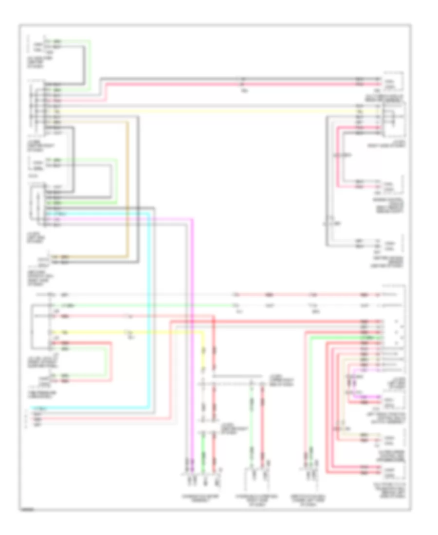
Computer Data Lines Wiring Diagram (1 of 2) for Toyota Land Cruiser 2014
List of elements for Computer Data Lines Wiring Diagram (1 of 2) for Toyota Land Cruiser 2014:
- (center left of dash) j/c e66
- (center right of dash) j/c e69
- (right rear of engine compt) j/c a37 & c52
- A/c amplifier (center of dash)
- A37
- A38
- Assembly
- Atx+
- Atx-
- B13
- B15
- Bat
- Batt
- C1 (left rear of engine)
- C52
- Ca1h
- Ca1l
- Ca2h
- Ca2l
- Canh
- Canl
- Center air bag sensor (center of dash)
- D14
- D17
- D18
- D56
- Data link connector 3
- Dcm (telematics transceiver) (rear of center console)
- Dia
- E1 (left side of dash)
- E2 (center of dash)
- E35
- E47
- Ea3
- Ecu assembly
- Ecu-b1 fuse 5a
- Ecu-ig 1 fuse 5a
- Ee1
- El1
- Engine control module (right rear of engine compt)
- Engine room r/b
- F18
- F40
- F56
- F57
- F58
- F60
- Fe4
- Fe7
- Fl1
- Gnd
- Hot at all times
- Hot in on or start
- Ig1
- Ig2
- Ign fuse 10a
- J/c e58 (upper left end of dash)
- J/c e59 (upper left end of dash)
- J/c e60 (upper right end of dash)
- J/c e61 (upper right end of dash)
- J/c e62 (left end of dash)
- J/c e72 (right side of dash)
- J/c e75 (left end of dash)
- L35
- Left cowl side j/b (left end of dash)
- Lc2
- Multi-display
- Multi-media interface
- Multi-media module receiver assembly (w/ navigation system)
- Network gateway ecu (right side of dash)
- Obd fuse 7.5a
- Occupant detection ecu (under passenger's seat)
- Parking assist ecu (center right of dash)
- Pf1
- Pnk
- Radio receiver assembly (w/o navigation system)
- Red
- Sil
- Stereo component amplifier (under driver's seat)
- Tac
- Tach
- Tc-
- Tx+
- Tx-
- Tx1+
- Tx1-
- Tx3+
- Tx3-
- Txm+
- Txm-
Computer Data Lines Wiring Diagram (2 of 2) for Toyota Land Cruiser 2014
List of elements for Computer Data Lines Wiring Diagram (2 of 2) for Toyota Land Cruiser 2014:
- (left "b" pillar) k1
- 4 wheel drive ecu (right side of dash)
- A24
- A27
- Aa1
- Ae3
- Can+
- Can-
- Canh
- Canl
- Cann
- Canp
- Certification ecu (under left side of dash)
- Clearance warning ecu (center of dash)
- Combination meter assembly
- Distance control ecu assembly (center of dash)
- E29
- E42
- E85
- Ea1
- Ek2
- Ek4
- El1
- Fe4
- I18
- Ie4
- J/c e68 (center right of dash)
- J/c e70 (center right of dash)
- J/c e71 (upper right end of dash)
- J/c e73 (upper right end of dash)
- J/c e74 (upper left end of dash)
- J/c e76 (left end of dash)
- J/c f21 (upper right side of dash)
- J/c k28 & k29 (top of left rear wheelwell)
- J/c l29, l30 & l31 (front of right quarter panel)
- K28
- K29
- Kl1
- Kc1
- L29
- L30
- L31
- Left front position control ecu & switch assembly
- Main body ecu (left end of dash)
- Mpx+
- Mpx-
- Mpx1
- Mpx2
- Multiplex tilt & telescopic ecu (behind left side of dash)
- Outer mirror control ecu (driver's door)
- Pnk
- Red
- Seat belt control ecu (under left side of dash)
- Skid control ecu (left rear engine compt)
- St-plug
- Steering control ecu (on steering column)
- Steering sensor (left side of dash)
- Tire pressure warning ecu
- W/ multi-terrain monitor
- W/o multi-terrain monitor
- Windshield wiper ecu (right side of dash)
- Yaw rate sensor (under center of dash, on transmission tunnel)
- C15
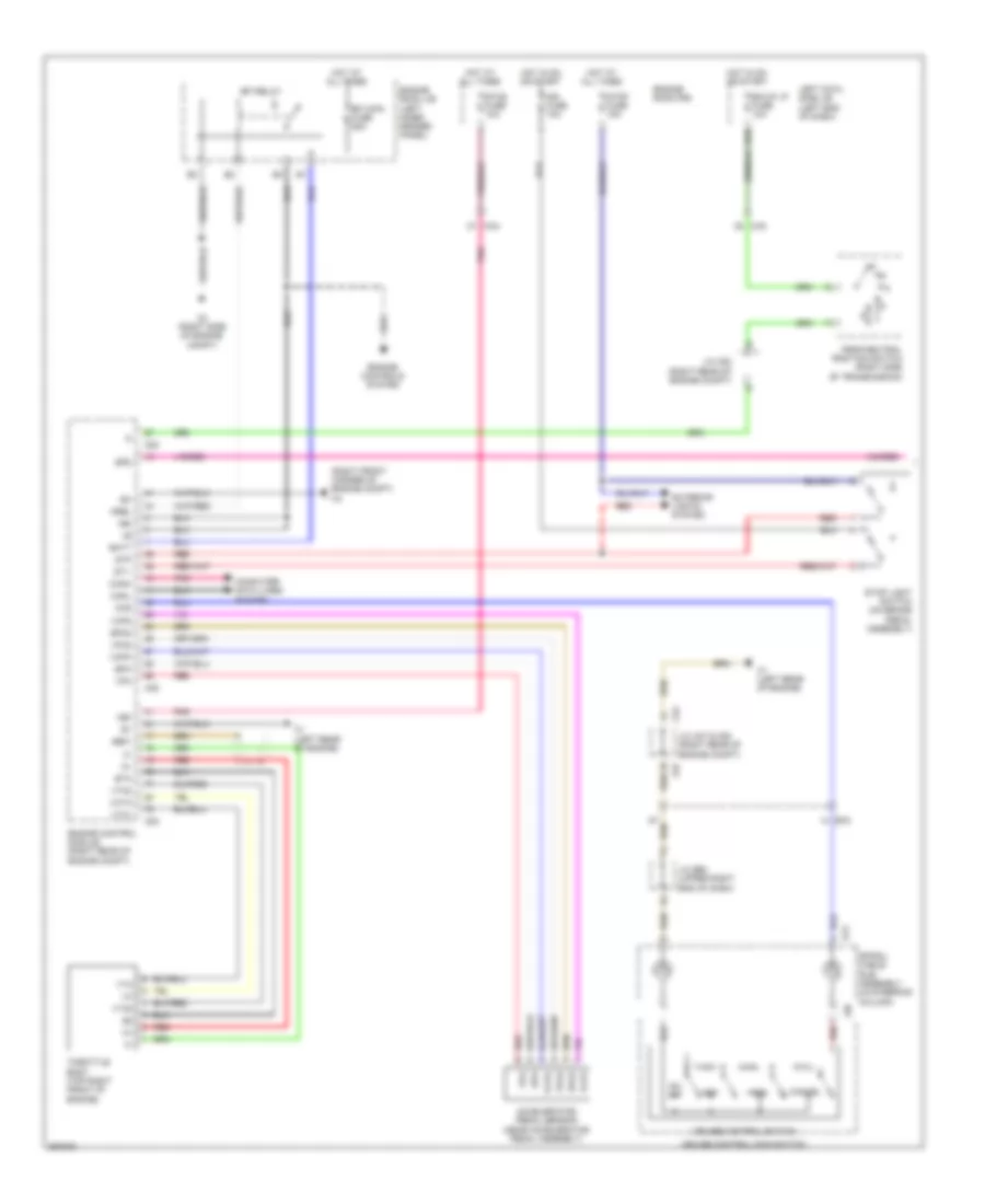
CRUISE CONTROL
Cruise Control Wiring Diagram (1 of 2) for Toyota Land Cruiser 2014
List of elements for Cruise Control Wiring Diagram (1 of 2) for Toyota Land Cruiser 2014:
- (right front corner of engine compt) a4
- +b2
- +bm
- +res
- -set
- A3 (right side of engine compt)
- A37
- A38
- Accelerator pedal sensor (near accelerator pedal assembly)
- B23
- Batt
- Bk/up lp fuse 10a
- C1 (left rear of engine)
- C52
- C53
- Ca3
- Cancel
- Canh
- Canl
- Ccs
- Computer data lines system
- Cruise control main switch
- Cruise control switch
- E12
- Ea3
- Efi main fuse 25a
- Efi relay
- Engine control module (right rear of engine compt)
- Engine controls system
- Engine room j/b (left inner fender panel)
- Engine room r/b
- Epa
- Epa2
- Eta
- Etcs fuse 10a
- Exterior lights system
- Ge01
- Hot at all times
- Hot in on or start
- Ign fuse 10a
- J/c a37 & c52 (right rear of engine compt)
- J/c c52 (right rear of engine compt)
- J/c e60 (upper right end of dash)
- Left cowl side j/b (left end of dash)
- Mrel
- On- off
- Park/neutral position switch (right side of transmission)
- Pnk
- Red
- Spd
- Spiral cable sub assembly (in steering column)
- St1-
- Stop fuse 15a
- Stop light switch (on brake pedal assembly)
- Stp
- Throttle body (top right front of engine)
- Vcp2
- Vcpa
- Vcta
- Vpa
- Vpa2
- Vta
- Vta1
- Vta2
- Z36
Cruise Control Wiring Diagram (2 of 2) for Toyota Land Cruiser 2014
List of elements for Cruise Control Wiring Diagram (2 of 2) for Toyota Land Cruiser 2014:
- A1 (left side of engine compt)
- A24
- A37
- Ak2
- Az1
- Az2
- C1 (left rear of engine)
- C52
- Can
- Canh
- Canl
- Combination meter assembly
- Computer data lines system
- Cruise ind
- Ea1
- Ea2
- Ea3
- Engine room r/b
- Fl+
- Fl-
- Fr+
- Fr-
- Hot in on or start
- Ig+
- J/c a37 & c52 (right rear of engine compt)
- J/c e58 (upper left end of dash)
- J/c e60 (upper right end of dash)
- Left front speed sensor (left front hub assembly)
- Left rear speed sensor (left rear hub assembly)
- Met fuse 5a
- Nca
- Nk1
- Nz1
- One step dim
- Red
- Right front speed sensor (right front hub assembly)
- Right rear speed sensor (right rear hub assembly)
- Rl+
- Rl-
- Rr+
- Rr-
- Skid control ecu (left rear engine compt)
- Sp1
Dynamic Laser Cruise Control Wiring Diagram (1 of 2) for Toyota Land Cruiser 2014
List of elements for Dynamic Laser Cruise Control Wiring Diagram (1 of 2) for Toyota Land Cruiser 2014:
- +b2
- +bm
- A1 (left side of of engine compt)
- A3 (right side of engine compt)
- A38
- A4 (right front corner of engine compt)
- Accelerator pedal sensor assembly (near accelerator pedal assembly)
- Batt
- Brk lp relay
- C53
- Ca3
- Canh
- Canl
- Cchg
- Ccs
- Computer data lines system
- Ea2
- Ecm (right rear of engine compt)
- Efi main fuse 25a
- Efi main relay
- Engine controls system
- Engine room j/b (left inner fender panel)
- Engine room r/b
- Epa
- Epa2
- Eta
- Etcs fuse 10a
- Ge01
- Gnd
- Hot at all times
- Hot in on or start
- Ign fuse 10a
- Igsw
- J/c c52 (right rear of engine compt)
- Lgnd
- Met fuse 5a
- Mrel
- Out
- Park/neutral position switch (right side of transmission)
- Pnk
- Red
- Spd
- St1-
- Stop fuse 15a
- Stop light control relay assembly (left side of dash)
- Stop light switch assembly (on brake pedal assembly)
- Stp
- Throttle body assembly (top right front of engine)
- Vcp2
- Vcpa
- Vcta
- Vpa
- Vpa2
- Vta
- Vta1
- Vta2
Dynamic Laser Cruise Control Wiring Diagram (2 of 2) for Toyota Land Cruiser 2014
List of elements for Dynamic Laser Cruise Control Wiring Diagram (2 of 2) for Toyota Land Cruiser 2014:
- (center of dash) distance control ecu assembly
- (upper left end of dash) j/c e58
- +res
- -set
- A1 (left side of of engine compt)
- A24
- A37
- Ak2
- Az1
- Az2
- B12
- B23
- Bk/up lp fuse 10a
- C1 (left rear of engine)
- C26
- C52
- Ca3
- Can
- Cancel
- Canh
- Canl
- Ccs
- Combination meter assembly
- Computer data lines system
- Cruise control main switch
- Cruise control switch
- Cruise ind
- Dist
- Distance control switch
- E12
- Ea1
- Ea2
- Ea3
- Ecc
- Ecu ig 2 fuse 10a
- Ecu ig 3 fuse 5a
- Exterior lights system
- Fl+
- Fl-
- Fr+
- Fr-
- Gnd
- Hot in on or start
- Ig+
- Igb
- J/c a37 & c52 (right rear of engine compt)
- J/c e60 (upper right end of dash)
- J/c e61 (upper right end of dash)
- Left cowl side j/b (left end of dash)
- Left front speed sensor (left front hub assembly)
- Left rear speed sensor (left rear hub assembly)
- Lgnd
- Lrdd
- Lrrd
- Millimeter wave radar sensor assembly (center of front grille)
- Mode
- Nca
- Nk1
- Nz1
- On- off
- One step dim
- Pnk
- R/n
- Radar cruise ind
- Red
- Red red
- Right cowl side j/b (right end of dash)
- Right front speed sensor (right front hub assembly)
- Right rear speed sensor (right rear hub assembly)
- Right steering pad switch
- Rl+
- Rl-
- Rr+
- Rr-
- Sgnd
- Skid control ecu w/ actuator assembly (left rear engine compt)
- Sp1
- Spiral cable sub-assembly (in steering column)
- Steering pad switch assembly
- Stp
- Stp2
- Stpo
- Wash
- Wiper/ washer system
- Z35
- Z36
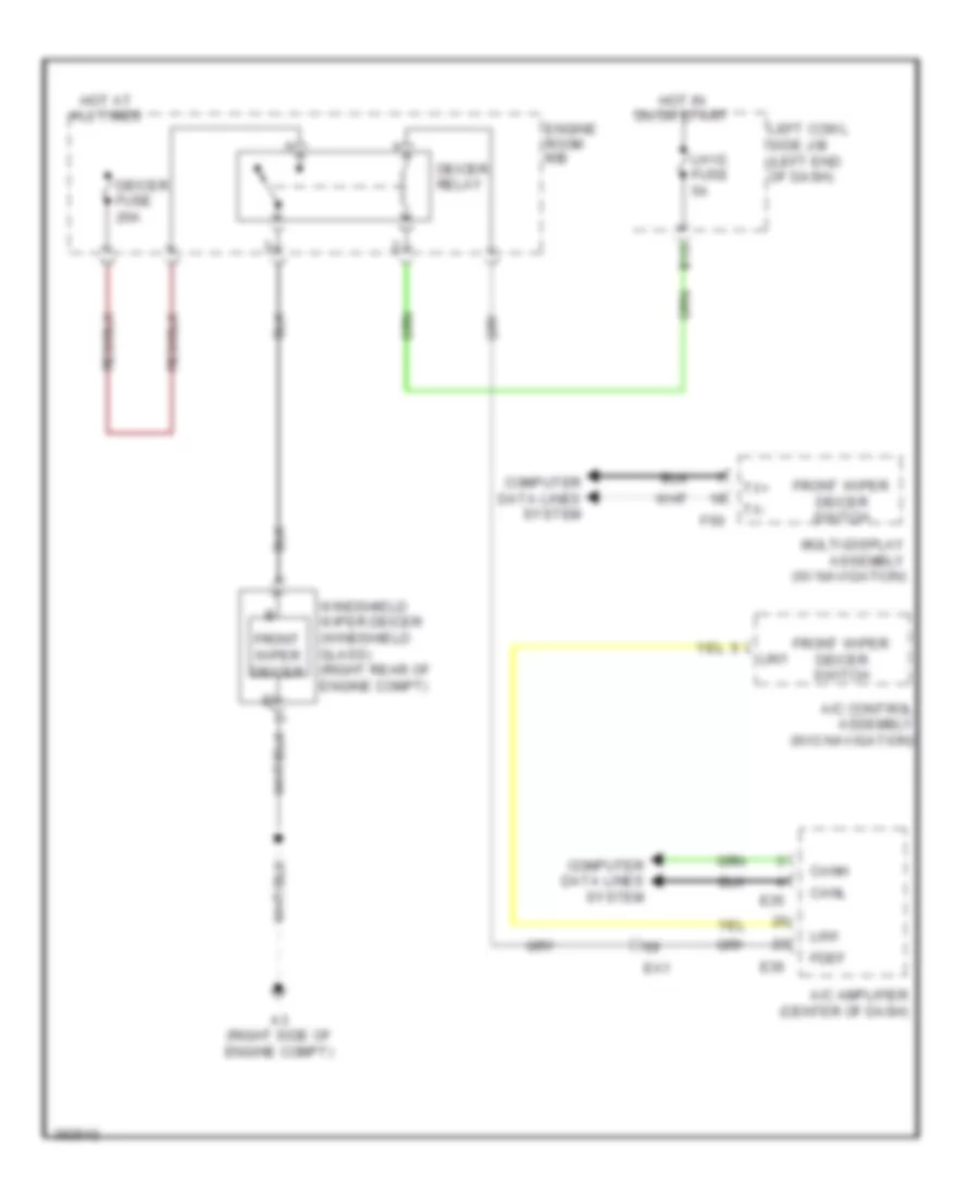
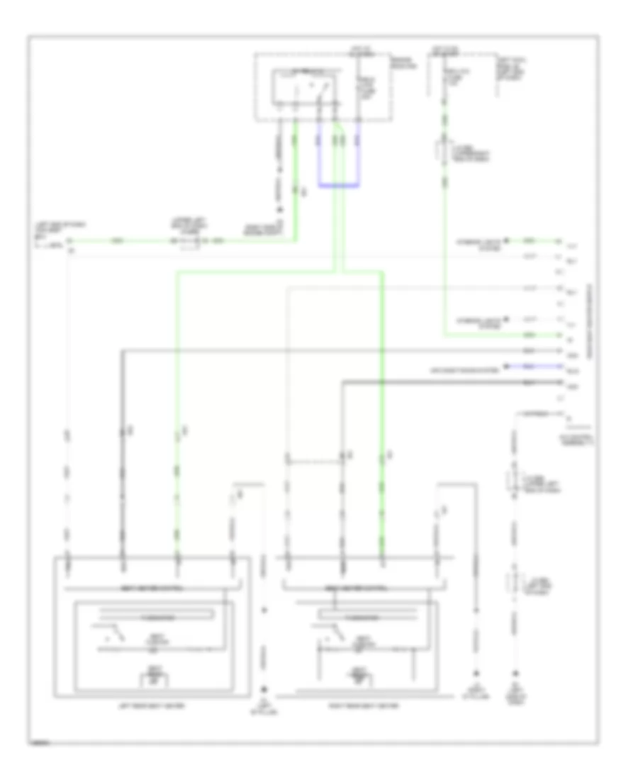
DEFOGGERS
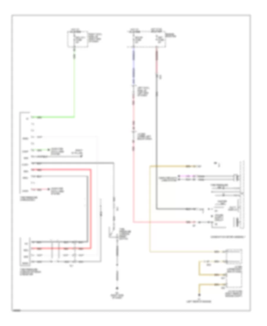
Front Deicer Wiring Diagram for Toyota Land Cruiser 2014
List of elements for Front Deicer Wiring Diagram for Toyota Land Cruiser 2014:
- A/c amplifier (center of dash)
- A/c control assembly (w/o navigation)
- A3 (right side of engine compt)
- B10
- Canh
- Canl
- Computer data lines system
- Deicer fuse 20a
- Deicer relay
- E35
- E36
- Ea1
- Engine room r/b
- F60
- Fdef
- Front wiper deicer
- Front wiper deicer switch
- Hot at all times
- Hot in on or start
- Left cowl side j/b (left end of dash)
- Lh ig fuse 5a
- Lin1
- Multi-display assembly (w/ navigation)
- Tx+
- Tx-
- Windshield wiper deicer (windshield glass) (right rear of engine compt)
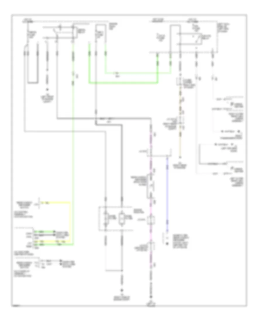
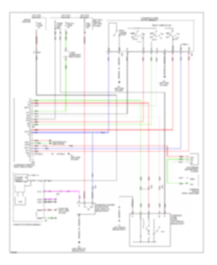
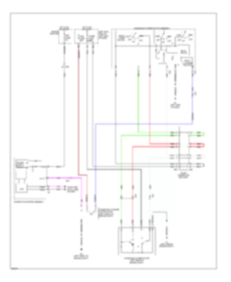
Mirror Heater & Rear Defogger Wiring Diagram for Toyota Land Cruiser 2014
List of elements for Mirror Heater & Rear Defogger Wiring Diagram for Toyota Land Cruiser 2014:
- A/c amplifier (center of dash)
- A/c control assembly (w/o navigation)
- A/c ig fuse 10a
- A2 (left front of engine compt)
- A3 (right side of engine compt)
- A37
- Ak1
- C2 (right rear of engine)
- C52
- Canh
- Canl
- Computer data lines system
- D11
- D19
- D38
- D50
- Def 2 fuse 5a
- Defog fuse 30a
- Defog relay
- E35
- E36
- Ea1
- Ea3
- Engine room r/b
- F60
- Fe4
- Hot at all times
- Hot in on or start
- I1 (right passenger's door)
- I2 (left driver's door)
- Ie2
- Ie6
- J/c a37 & c52 (right rear of engine compt)
- J/c e60 (upper right end of dash)
- J/c s15 (center of liftgate)
- J/c s16
- K2 (left "d" pillar)
- Left cowl side j/b (left end of dash)
- Left outer rear view mirror assembly
- Lin1
- Mir fuse 15a
- Mir htr relay
- Mirror heater
- Multi-display assembly (w/ navigation)
- Noise filter
- Noise filter (rear window defogger & stop light) (center top of liftgate)
- Rdef
- Rear window defogger (back door glass)
- Rear window defogger switch
- Right outer rear view mirror assembly
- S19
- S20
- Sk1
- Tx+
- Tx-
ELECTRONIC POWER STEERING
Electronic Power Steering Wiring Diagram for Toyota Land Cruiser 2014
List of elements for Electronic Power Steering Wiring Diagram for Toyota Land Cruiser 2014:
- (center of dash) e2
- (left side of dash) e1
- +bi
- +bo
- A37
- B13
- Bat
- Bmu
- Bmu+
- Bmv
- Bmv+
- Bmw
- Bmw+
- Buzzer
- C1 (left rear of engine)
- C52
- Can
- Canh
- Canl
- Combination meter assembly
- Computer data lines system
- D14
- E90
- E91
- E92
- Ea2
- Ea3
- Ecu-b1 fuse 5a
- Ecu-ig 2 fuse 10a
- Ecu-ig 4 fuse 5a
- Engine room r/b
- Ess
- Hot at all times
- Hot in on or start
- Ig+
- J/c a37 & c52 (right rear of engine compt)
- J/c e59 (upper left end of dash)
- J/c e60 (upper right end of dash)
- J/c e61 (upper right end of dash)
- Left cowl side j/b (left end of dash)
- Lg+
- Lv+
- Met fuse 5a
- Multi display
- Nca
- Pgd2
- Pgnd
- Pig
- Red
- Rg+
- Right cowl side j/b (right end of dash)
- Rv+
- S1+
- S2+
- Sg2+
- Sil
- Ss1+
- Ss1-
- Steering actuator assembly (on steering column)
- Steering control ecu (on steering column)
- Steering sensor (left side of dash)
- Vgrs fuse 40a
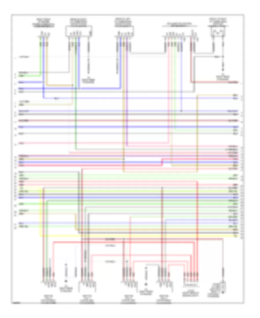
ENGINE PERFORMANCE
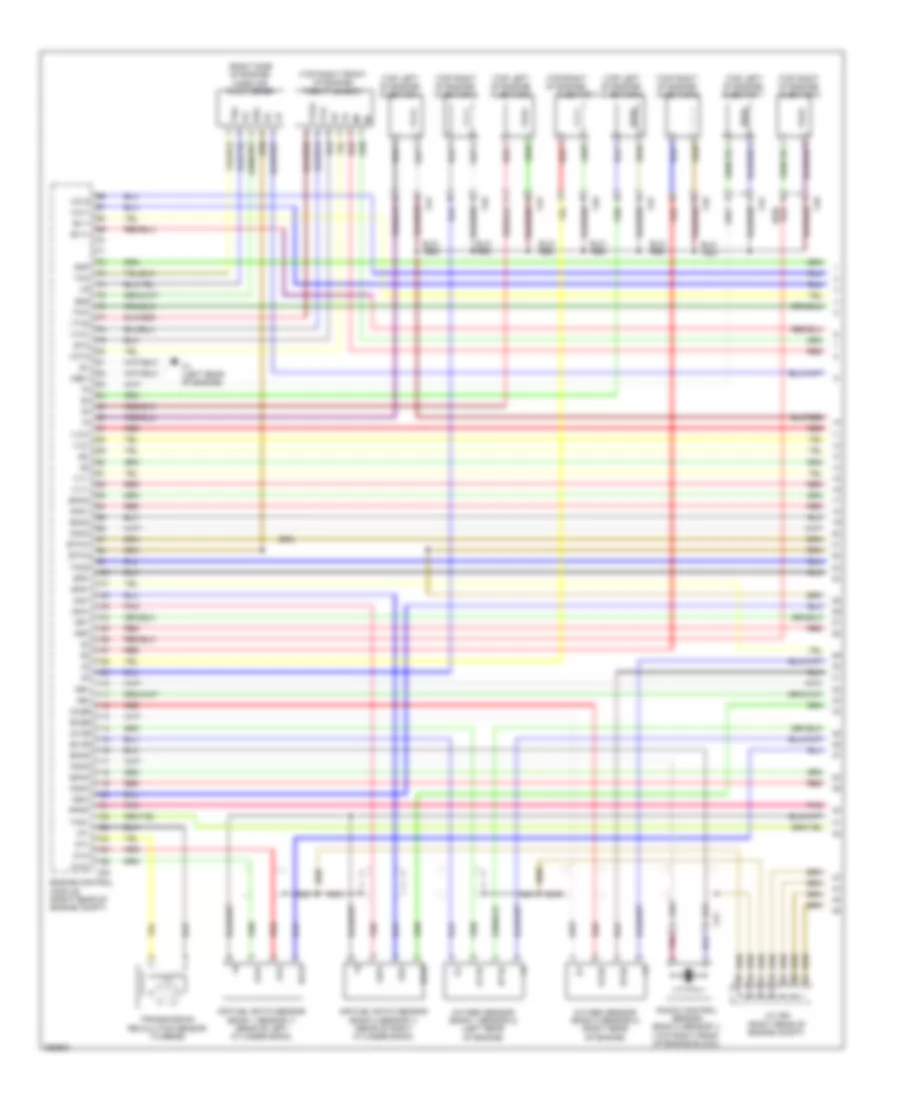
5.7L
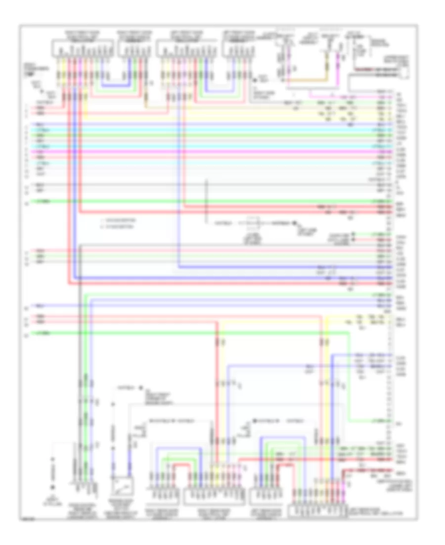
5.7L, Engine Performance Wiring Diagram (1 of 7) for Toyota Land Cruiser 2014
List of elements for 5.7L, Engine Performance Wiring Diagram (1 of 7) for Toyota Land Cruiser 2014:
- (right side of engine) mass air flow meter
- (top left of engine) injector 1
- (top left of engine) injector 3
- (top left of engine) injector 5
- (top left of engine) injector 7
- (top right front of engine) throttle body
- (top right of engine)
- (top right of engine) injector 2
- (top right of engine) injector 6
- (top right of engine) injector 8
- A1a+
- A1a-
- A2a+
- A2a-
- Air fuel ratio sensor (bank 1 sensor 1) (rear of left cylinder bank)
- Air fuel ratio sensor (bank 2 sensor 1) (rear of right cylinder bank)
- C1 (left rear of engine)
- C53
- Cu1
- Ca1
- Ca2
- E2g
- Ekn2
- Ekn4
- Eknk
- Engine control module (right rear of engine compt)
- Enk3
- Eta
- Etha
- Ethw
- Ev1+
- Ev1-
- Ex1b
- Ex2b
- G2-
- Ha1a
- Ha2a
- Ht1b
- Ht2b
- Igf1
- Igf2
- Injector 4
- J/c c50 (right rear of engine compt)
- Knk1
- Knk2
- Knk3
- Knk4
- Knock control sensor (bank 2 sensor 1) (top right front of engine block)
- Me01
- Nca
- Ne+
- Ne-
- Nsw
- Nt+
- Nt-
- Ox1b
- Ox2b
- Oxygen sensor (bank 1 sensor 2) (left rear of engine)
- Oxygen sensor (bank 2 sensor 2) (right rear of engine)
- Pnk
- Ppmp
- Psp
- Red
- Sp2+
- Sp2-
- Tha
- Tho1
- Tho2
- Thw
- Transmission revolution sensor (turbine)
- Vcta
- Vcv1
- Vcv2
- Vta
- Vta1
- Vta2
- Vv1+
- Vv1-
- Vv2+
- Vv2-
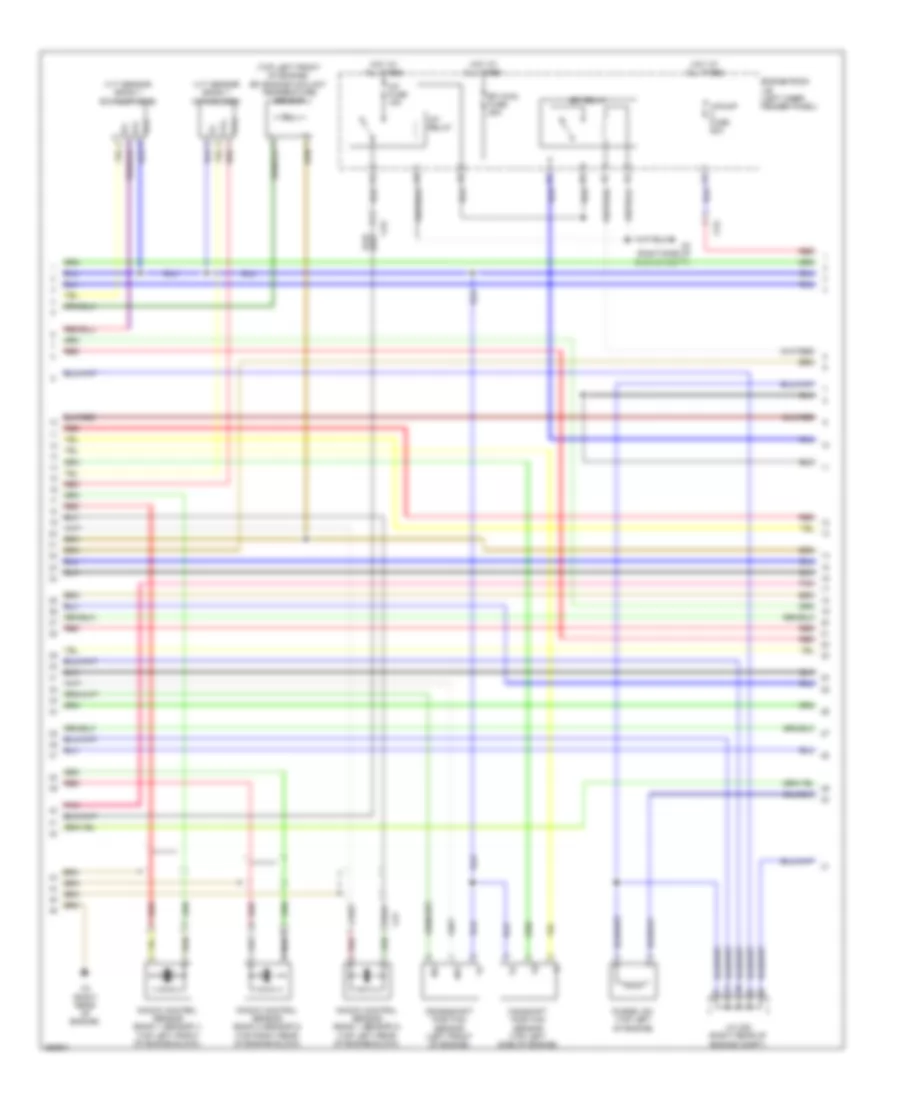
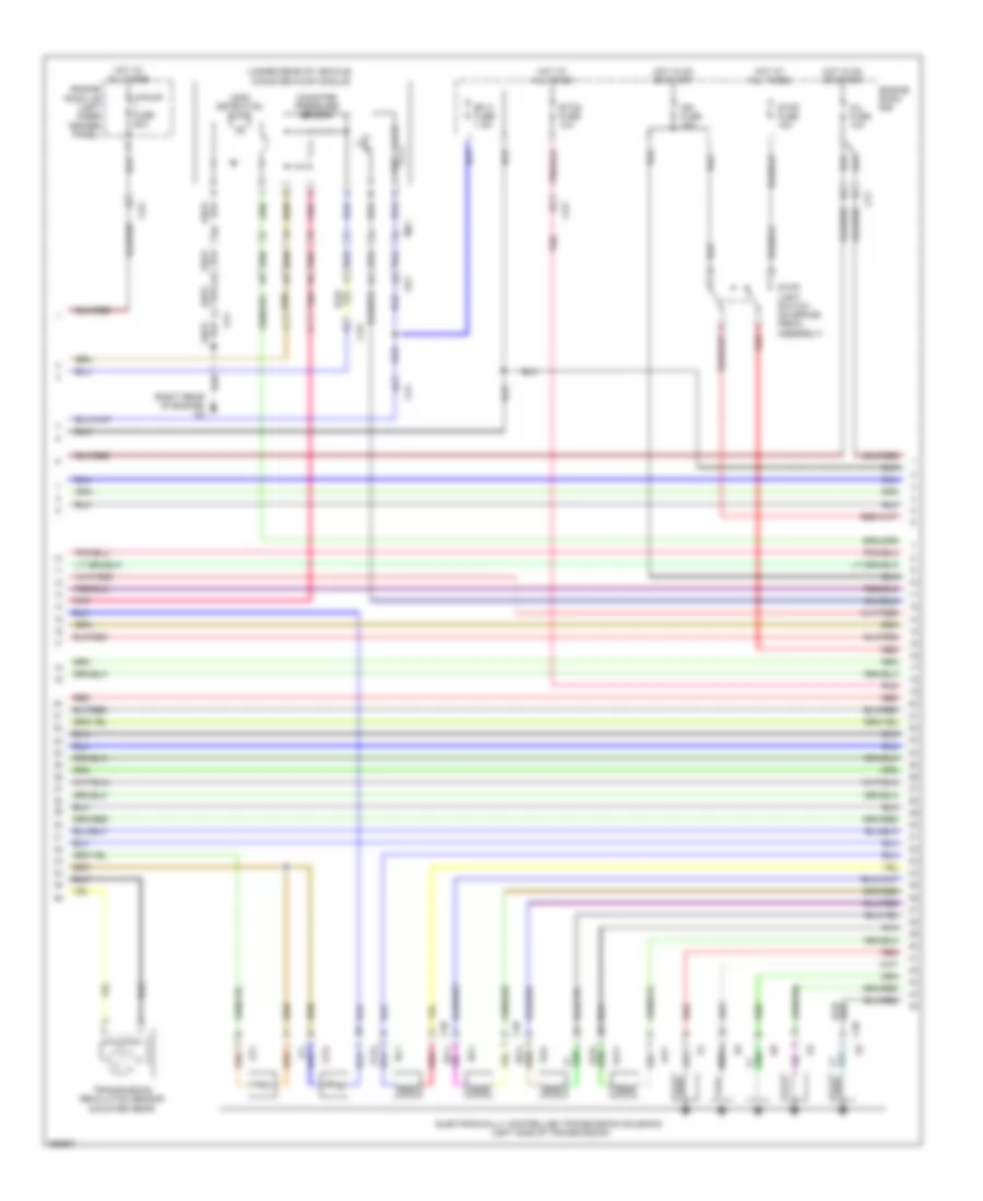
5.7L, Engine Performance Wiring Diagram (2 of 7) for Toyota Land Cruiser 2014
List of elements for 5.7L, Engine Performance Wiring Diagram (2 of 7) for Toyota Land Cruiser 2014:
- (top left front of engine) efi engine coolant temperature sensor
- A/f fuse 15a
- A/f relay
- A/pump fuse 50a
- A3 (right side of engine compt)
- C3 (right rear of engine)
- Ca2
- Camshaft position sensor (top left side of engine)
- Crankshaft position sensor (left front of engine)
- Cu1
- Efi main fuse 25a
- Efi relay
- Engine room j/b (left inner fender panel)
- Ex+
- Ex-
- Hot at all times
- J/c c50 (right rear of engine compt)
- Knock control sensor (bank 1 sensor 1) (top left front of engine block)
- Knock control sensor (bank 1 sensor 2) (top left rear of engine block)
- Knock control sensor (bank 2 sensor 2) (top right rear of engine block)
- Ne+
- Ne-
- Pnk
- Purge vsv (top left of engine)
- Red
- Vc2
- Vvl+
- Vvl-
- Vvt sensor (bank 1 exhaust side)
- Vvt sensor (bank 1 intake side)
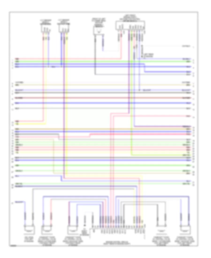
5.7L, Engine Performance Wiring Diagram (3 of 7) for Toyota Land Cruiser 2014
List of elements for 5.7L, Engine Performance Wiring Diagram (3 of 7) for Toyota Land Cruiser 2014:
- (front of left cylinder head) air pump assembly (bank 2)
- (left front engine compt) air injection control driver (bank 2)
- (left rear of engine) c1
- +b2
- Acis
- Airp
- Arp2
- Bat2
- C3 (right rear of engine)
- C31
- C32
- C53
- Ca3
- Camshaft timing oil control valve (bank 1 exhaust side) (top left front of engine)
- Camshaft timing oil control valve (bank 1 intake side) (top left front of engine)
- Camshaft timing oil control valve (bank 2 exhaust side) (top right front of engine)
- Camshaft timing oil control valve (bank 2 intake side) (top right front of engine)
- Di2
- E03
- Engine control module (right rear of engine compt)
- Ev2+
- Ev2-
- Ex+
- Ex-
- Oc1+
- Oc1-
- Oc2+
- Oc2-
- Oe1+
- Oe1-
- Oe2+
- Oe2-
- Pnk
- Prg
- Red
- Sip2
- Siv2
- Vc2
- Vp2
- Vsv (acis) (top left of engine)
- Vv2
- Vvr+
- Vvr-
- Vvt sensor (bank 2 exhaust side)
- Vvt sensor (bank 2 intake side)
5.7L, Engine Performance Wiring Diagram (4 of 7) for Toyota Land Cruiser 2014
List of elements for 5.7L, Engine Performance Wiring Diagram (4 of 7) for Toyota Land Cruiser 2014:
- (front of right cylinder head) air pump assembly (bank 1)
- (rear of left cylinder bank) air switching valve (bank 1)
- (rear of right cylinder bank) air switching valve (bank 2)
- (right front of engine) power steering oil pressure sensor
- Aip
- Aip2
- Air injection control driver (bank 1)
- Batt
- C2 (right rear of engine)
- C29
- C30
- E22
- Gnd
- Igf2
- Ignition coil 2 (top of right valve cover)
- Ignition coil 3 (top of left valve cover)
- Ignition coil 5 (top of left valve cover)
- Ignition coil 8 (top of right valve cover)
- Igt2
- Igt3
- Igt5
- Igt8
- J/c c51 (right rear of engine compt)
- Noise filter (ignition bank 1) (top right of engine)
- Pnk
- Psp
- Red
- Sip
- Siv
- Vc2
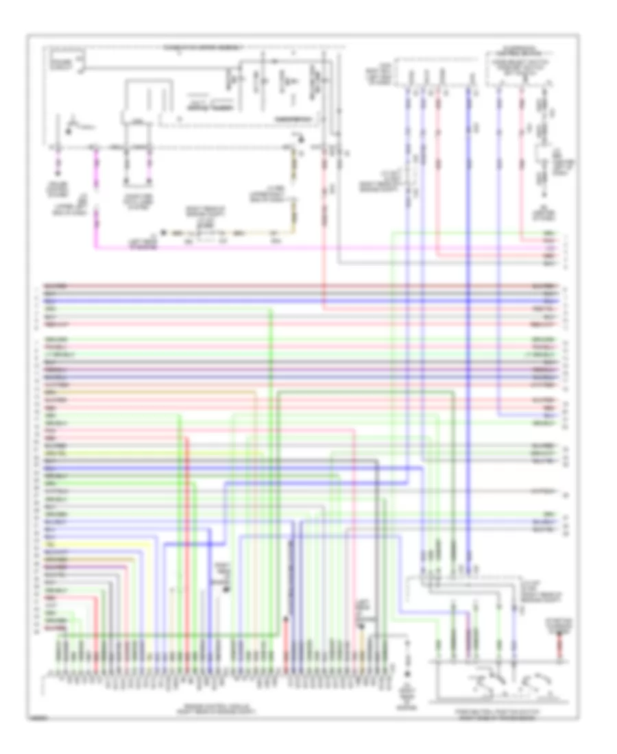
5.7L, Engine Performance Wiring Diagram (5 of 7) for Toyota Land Cruiser 2014
List of elements for 5.7L, Engine Performance Wiring Diagram (5 of 7) for Toyota Land Cruiser 2014:
- (right rear of engine) c2
- (under rear of vehicle) canister pump module
- A/pump fuse 50a
- Ak1
- C39
- C40
- Ca1
- Ca2
- Ca3
- Canister pressure sensor
- Efi 2 fuse 7.5a
- Electronically controlled transmission solenoid (left side of transmission)
- Engine room j/b (left inner fender panel)
- Engine room r/b
- Etcs fuse 10a
- Hot at all times
- Hot in on or start
- Ign fuse 10a
- Inj fuse 10a
- Leak detection pump
- Mk1
- Ot+
- Ot-
- Ot2+
- Ot2-
- Pnk
- Red
- Sl1+
- Sl1-
- Sl2+
- Sl2-
- Slt+
- Slt-
- Slu+
- Slu-
- Stop fuse 15a
- Stop light switch (on brake pedal assembly)
- Transmission revolution sensor (counter gear)
- Vent valve
5.7L, Engine Performance Wiring Diagram (6 of 7) for Toyota Land Cruiser 2014
List of elements for 5.7L, Engine Performance Wiring Diagram (6 of 7) for Toyota Land Cruiser 2014:
- (left rear of engine) c1
- (right rear of engine compt) j/c a37 & c52
- (right rear of engine) c2
- +bm
- 2nd
- A/t p ind
- A37
- Accr
- Aid2
- Aidi
- Airv
- Alt
- Buzzer
- C1 (left rear of engine)
- C2 (right rear of engine)
- C52
- C53
- Can
- Canh
- Canl
- Chk
- Combination meter assembly
- Computer data lines system
- Cruise control system
- E01
- E02
- E04
- E05
- E2 (center of dash)
- Ea3
- Ect pwr ind
- Engine control module (right rear of engine compt)
- Ge01
- Ha1a
- Ha2a
- Ht1b
- Ht2b
- Ig+
- Igt1
- Igt2
- Igt3
- Igt4
- Igt5
- Igt6
- Igt7
- Igt8
- J/c a37 & c52 (right rear of engine compt)
- J/c e58 (upper left end of dash)
- J/c e60 (upper right end of dash)
- J/c e66 (center left of dash)
- Main body ecu (left end of dash)
- Malfunction ind lamp
- Master ind
- Mode select switch mode set switch ect switch
- Multi display
- One step dim
- Park/neutral position switch (right side of transmission)
- Pnk
- Power circuit
- Red
- Sl1+
- Sl1-
- Sl2+
- Sl2-
- Slt+
- Slt-
- Slu+
- Slu-
- Star
- Starting/ charging system
- Starting/charging system
- Str
- Str2
- Stsw
- Suspension control switch
- Ve1
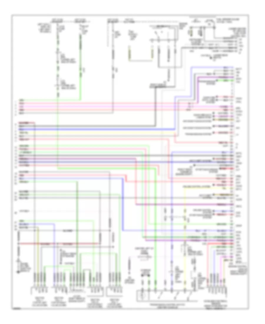
5.7L, Engine Performance Wiring Diagram (7 of 7) for Toyota Land Cruiser 2014
List of elements for 5.7L, Engine Performance Wiring Diagram (7 of 7) for Toyota Land Cruiser 2014:
- (center left of dash) j/c e66
- (under center of vehicle) fuel pump control ecu
- (under rear seats) n1
- +b2
- A3 (right side of engine compt)
- A38
- A4 (right front corner of engine compt)
- Ac1
- Accelerator pedal sensor (near accelerator pedal assembly)
- Accr
- Act
- Aip
- Aip2
- Air conditioning system
- Ak1
- Ak2
- Alt
- Anti-theft system
- Arv2
- B23
- Batt
- Bk/up lp fuse 10a
- C2 (right rear of engine)
- Ca3
- Canh
- Canl
- Cchg
- Ccs
- Computer data lines system
- Cruise control system
- D55
- E2 (center of dash)
- Ea2
- Ea3
- Efi main 2 fuse 20a
- Efi relay 2
- Engine control module (right rear of engine compt)
- Engine room r/b
- Epa
- Epa2
- Fp-
- Fpc
- Fuel sender gauge (in fuel tank)
- Gnd
- Hot at all times
- Hot in on or start
- Igf1
- Ignition coil 1 (top of left valve cover)
- Ignition coil 4 (top of right valve cover)
- Ignition coil 6 (top of right valve cover)
- Ignition coil 7 (top of left valve cover)
- Igsw
- Igt1
- Igt4
- Igt6
- Igt7
- Imi
- Imo
- Instrument cluster system
- Interior lights system
- J/c c51 (right rear of engine compt)
- J/c e58 (upper left end of dash)
- J/c e59 (upper left end of dash)
- J/c e60 (upper right end of dash)
- Kn1
- Left cowl side j/b (left end of dash)
- Lh-ig fuse 5a
- Met fuse 5a
- Mpmp
- Mrel
- Noise filter (ignition bank 2)
- Pnk
- Pump
- Pwr
- Red
- Sftd
- Sftu
- Snwi
- Spd
- St1-
- Sta
- Starting/charging system
- Stp
- Stsw
- Tach
- Tfn
- Transmission control switch (center console)
- Transmissions system
- Vcp2
- Vcpa
- Vpa
- Vpa2
- Vpmp
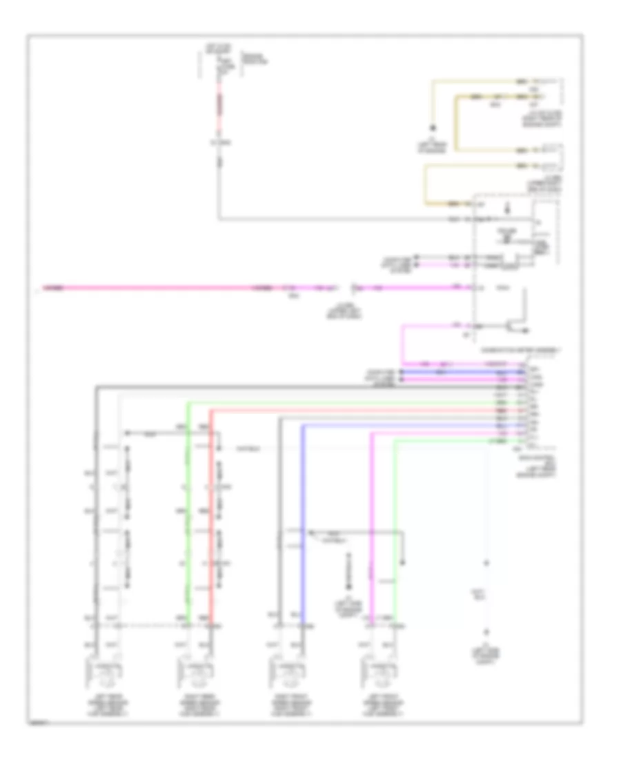
EXTERIOR LIGHTS
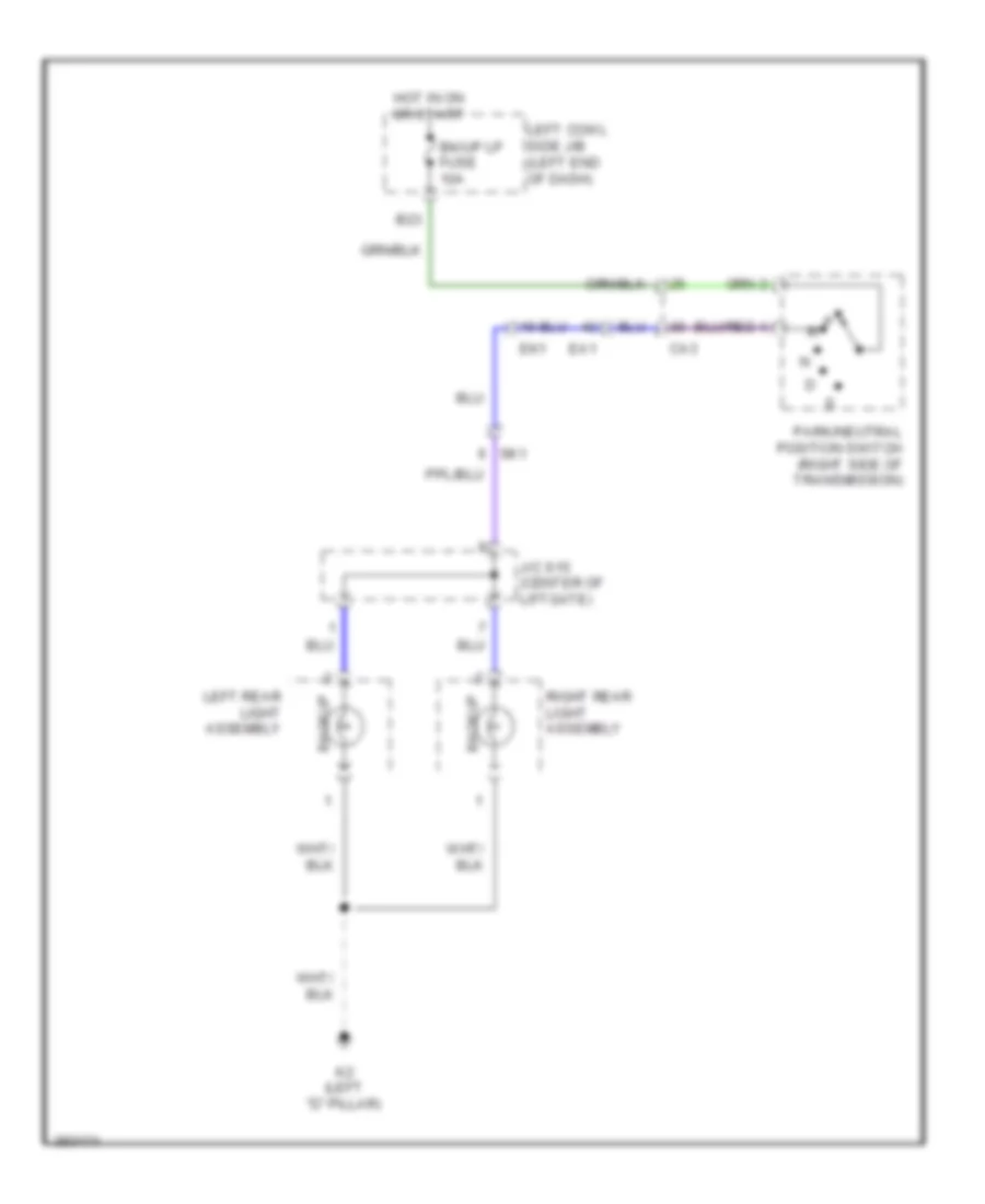
Backup Lamps Wiring Diagram for Toyota Land Cruiser 2014
List of elements for Backup Lamps Wiring Diagram for Toyota Land Cruiser 2014:
- B23
- Backup
- Bk/up lp fuse 10a
- Ca3
- Ea1
- Ek1
- Hot in on or start
- J/c s15 (center of liftgate)
- K2 (left "d" pillar)
- Left cowl side j/b (left end of dash)
- Left rear light assembly
- P r
- Park/neutral position switch (right side of transmission)
- Right rear light assembly
- Sk1
Exterior Lamps Wiring Diagram (1 of 2) for Toyota Land Cruiser 2014
List of elements for Exterior Lamps Wiring Diagram (1 of 2) for Toyota Land Cruiser 2014:
- (left side of dash)
- A2 (left front of engine compt)
- A4 (right front corner of engine compt)
- A40
- A41
- A44
- A45
- Aa3
- Auto
- B12
- B22
- Backup lamps circuit
- C22
- D55
- Dcty
- E1 (left side of dash)
- Ea2
- Ea3
- Ecu ig 2 fuse 10a
- Engine room r/b
- F1 (right side of dash)
- F603
- Fe1
- Haz
- Hazard switch
- Hazard warning signal switch assembly
- Head
- Headlight dimmer switch assembly
- Hot at all times
- Hot in on or start
- Interior lights system
- J/c e58 (upper left end of dash)
- J/c e59 (upper left end of dash)
- J/c e62 (left end of dash)
- J/c e89 (left end of dash)
- K2 (left "d" pillar)
- Lcty
- Left
- Left cowl side j/b (left end of dash)
- Left headlight assembly
- Left rear light assembly
- Lh ig fuse 5a
- Light backup
- Light control switch
- Main body ecu
- Marker side
- Multi-display assembly
- Off
- Parking
- Pcty
- Rcty
- Red
- Right
- Right headlight assembly
- Right rear light assembly
- Shift lock control ecu (center of dash)
- Side marker
- Stp
- Tail
- Tail fuse 15a
- Tail relay
- Trly
- Turn
- Turn haz fuse 15a
- Turn signal flasher (left end of dash)
- Turn signal switch
- W/ navigation system
- W/o navigation system
Exterior Lamps Wiring Diagram (2 of 2) for Toyota Land Cruiser 2014
List of elements for Exterior Lamps Wiring Diagram (2 of 2) for Toyota Land Cruiser 2014:
- (canada) tail ind
- (right rear of engine compt) j/c a37 & c52
- (upper right end of dash) j/c e60
- A1 (left side of engine compt)
- A24
- A37
- A38
- Ak1
- Ak2
- B13
- Brk lp relay
- C1 (left rear of engine)
- C52
- Center stop light assembly
- Combination meter assembly
- Cruise control system
- D14
- Diode (high mounted stop light) (top of left "d" pillar)
- Ea3
- Ecu b1 fuse 5a
- Ek1
- El1
- Engine control module (right rear of engine compt)
- Engine room j/b (left inner fender panel)
- Engine room r/b
- Gnd
- High mounted stop light
- Hot at all times
- J/c e59 (upper left end of dash)
- J/c s15 (center of liftgate)
- J/c s16
- K2 (left "d" pillar)
- Kl1
- L2 (right "d" pillar)
- Left cowl side j/b (left end of dash)
- Left license plate light assembly
- Left rear combination light assembly
- Left turn ind
- Lh j/b fuse 150a
- Noise filter (rear defogger & stop light) (center top of liftgate)
- One step dim
- Out
- Red
- Right license plate light assembly
- Right rear combination light assembly
- Right turn ind
- Side marker
- Sk1
- Sk2
- Skid control ecu (left rear engine compt)
- Stin
- Stop
- Stop fuse 15a
- Stop light control relay (left side of dash)
- Stop light switch (on brake pedal assembly)
- Stop tail/
- Stp
- Stp2
- Stpo
- Tail/ stop
- Towing brake controller (left side of dash)
- Towing converter
- Turn
Trailer Tow Wiring Diagram for Toyota Land Cruiser 2014
List of elements for Trailer Tow Wiring Diagram for Toyota Land Cruiser 2014:
- (left end of dash) j/c e89
- (right side of rear bumper) trailer socket
- A24
- A3 (right side of engine compt)
- Ak1
- Ak2
- Ak3
- B/up
- B10
- B12
- B23
- Batt
- Bk/up lp fuse 10a
- Brk
- Brk lp relay
- C13
- C17
- Ca3
- D57
- Diode (high mounted stop light) (top of left "d" pillar)
- E1 (left side of dash)
- E2 (center of dash)
- Ea1
- Ea2
- Ecu ig 2 fuse 10a
- Ek1
- El1
- Engine room j/b (left inner fender panel)
- Engine room r/b
- Exterior lamps circuit
- Gnd
- Hot at all times
- Hot in on or start
- J/c e58 (upper left end of dash)
- J/c e60 (upper right end of dash)
- J/c e62 (left end of dash)
- J/c e66 (center left of dash)
- K1 (left "b" pillar)
- K2 (left "d" pillar)
- Kl1
- Left cowl side j/b (left end of dash)
- Lh ig fuse 5a
- Lh j/b fuse 150a
- Ltin
- Ltot
- Main body ecu
- Mk2
- Mk3
- Out
- Panel fuse 10a
- Park/neutral position switch (right side of transmission)
- Qm1
- Qm2
- Red
- Right cowl side j/b (right end of dash)
- Rtin
- Rtot
- Skid control ecu (left rear engine compt)
- Stin
- Stop
- Stop fuse 15a
- Stop light control relay (left side of dash)
- Stop light switch (on brake pedal assembly)
- Stp
- Stpo
- Sttl
- Sttr
- Sub batt fuse 40a
- Sub batt relay
- Tail
- Tail relay
- Tow bk/ up fuse 7.5a
- Tow bk/up relay
- Tow brk fuse 30a
- Tow tail fuse 30a
- Tow tail relay
- Towing brake controller (left side of dash)
- Towing converter
- Towing fuse 30a
- Trly
- Turn signal flasher (left end of dash)
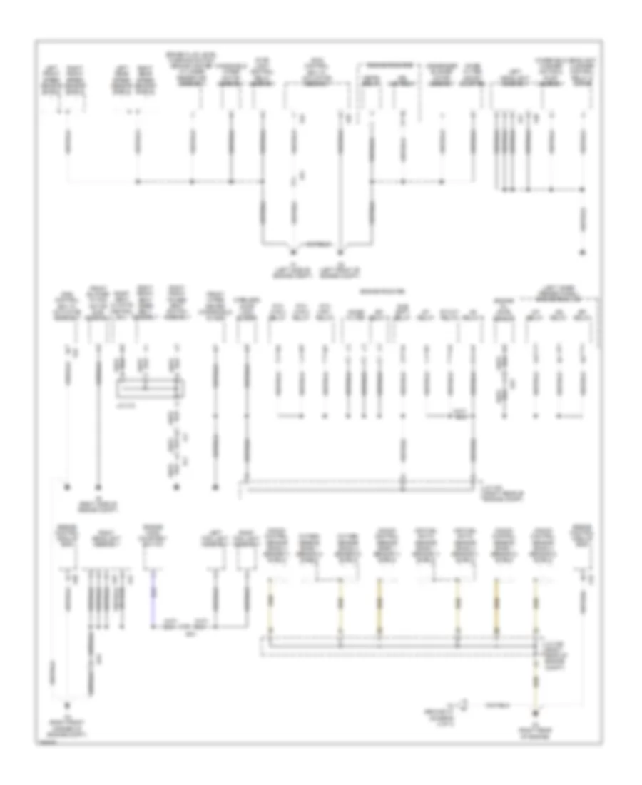
GROUND DISTRIBUTION
Ground Distribution Wiring Diagram (1 of 4) for Toyota Land Cruiser 2014
List of elements for Ground Distribution Wiring Diagram (1 of 4) for Toyota Land Cruiser 2014:
- (left inner fender panel) engine room j/b
- A/f relay
- A1 (left side of engine compt)
- A2 (left front of engine compt)
- A24
- A25
- A3 (right side of engine compt)
- A38
- A4 (right front corner of engine compt)
- A40
- A41
- A44
- A45
- Aa1
- Aa3
- Air fuel ratio sensor (bank 1 sensor 1) shield
- Air fuel ratio sensor (bank 2 sensor 1) shield
- Al1
- Ap2
- Ba1
- Brake fluid level warning switch (brake master cylinder reservoir assembly)
- C3 (right rear of engine)
- C53
- Condenser blower motor assembly
- Defog relay
- Drl mod relay
- Efi relay
- Efi relay 2
- Engine control module (ecm)
- Engine hood courtesy switch
- Engine oil level sensor
- Engine room r/b
- Front blower w/ fan motor sub- assembly
- Front wiper deicer (windshield glass)
- Headlight cleaner control relay & motor
- Ig1 relay 5
- Ig2 relay
- J/c a34 (right rear of engine compt)
- J/c c12
- J/c c50 (right rear of engine compt)
- Knock control sensor (bank 1 sensor 1) shield
- Knock control sensor (bank 1 sensor 2) shield
- Knock control sensor (bank 2 sensor 1) shield
- Knock control sensor (bank 2 sensor 2) shield
- Left fog light assembly
- Left front speed sensor shield
- Left headlight assembly
- Left rear speed sensor shield
- Lc1
- Noise filter
- Noise filter (ghost booster)
- Oxygen sensor (bank 1 sensor 2) shield
- Oxygen sensor (bank 2 sensor 2) shield
- Ptc htr 1 relay
- Ptc htr 2 relay
- Ptc htr 3 relay
- Right fog light assembly
- Right front power seat switch assembly
- Right front seat inner belt assembly
- Right front speed sensor shield
- Right headlight assembly
- Right rear speed sensor shield
- Right seat climate control ecu
- Skid control ecu w/ actuator assembly
- St cut relay
- St relay
- Stop light control relay assembly
- Sub batt relay
- To ground c1 (diagram 2 of 4)
- Windshield washer motor & pump assembly
- Windshield wiper motor assembly
- Wireless door lock buzzer
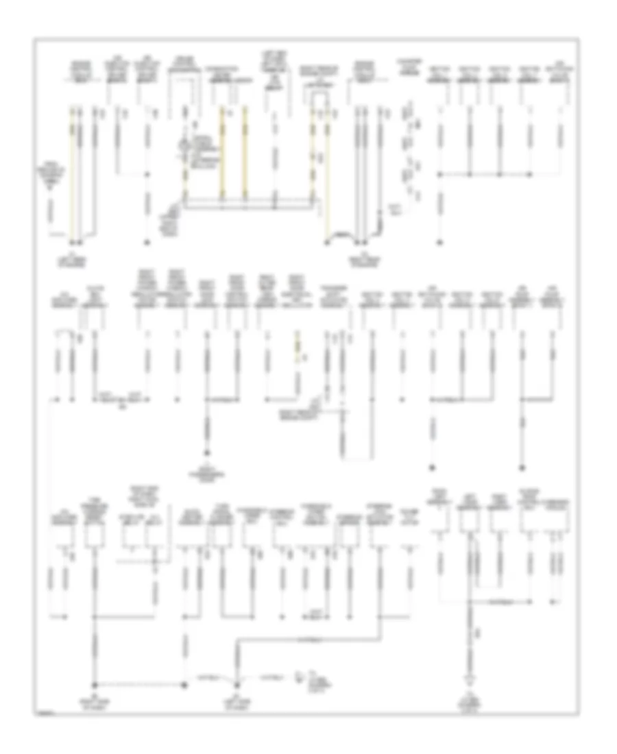
Ground Distribution Wiring Diagram (2 of 4) for Toyota Land Cruiser 2014
List of elements for Ground Distribution Wiring Diagram (2 of 4) for Toyota Land Cruiser 2014:
- (left end of dash) left cowl side j/b
- (right end of dash) right cowl side j/b
- (right rear of engine compt) j/c a37 & c52
- A/c amplifier assembly
- Air injection control driver (bank 1)
- Air injection control driver (bank 2)
- Air pump assembly (bank 1)
- Air pump assembly (bank 2)
- Air switching valve (bank 1)
- Air switching valve (bank 2)
- Ak1
- C1 (left rear of engine)
- C2 (right rear of engine)
- C30
- C32
- C37
- C43
- C44
- C52
- C53
- Ca1
- Canister pump module
- Combination meter assembly
- Cruise control main switch
- D19
- Dlc 3
- E1 (left side of dash)
- E15
- E16
- E3 (right side of dash)
- E34
- E35
- E36
- E85
- E90
- Ea3
- Engine control module (ecm)
- From ground c3 (diagram 1 of 4)
- Glove box light assembly
- I1 (right passenger's door)
- Ie2
- Ig 4 relay
- Ignition coil 1 assembly
- Ignition coil 2 assembly
- Ignition coil 3 assembly
- Ignition coil 4 assembly
- Ignition coil 5 assembly
- Ignition coil 6 assembly
- Ignition coil 7 assembly
- Ignition coil 8 assembly
- J/c c50 (right rear of engine compt)
- J/c e60 (upper right end of dash)
- Left visor assembly
- Mir htr relay
- Mk1
- Overhead module
- Power tilt motor
- Quick heater assembly
- Re2
- Right front door control switch assembly
- Right front door electrical key oscillator
- Right front door lock assembly
- Right front power window regulator motor assembly
- Right front power window regulator switch assembly
- Right outer rear- view mirror assembly
- Right visor assembly
- Room light assembly
- Sliding roof control ecu
- Spiral cable assembly (in steering e12 column)
- Steering control ecu
- Steering lock actuator assembly
- Steering sensor
- Strg htr relay
- Tire pressure warning reset switch
- To j/c e62 (diagram 3 of 4)
- Transfer shift actuator assembly
- Turn signal flasher assembly
- Windshield wiper ecu
- Windshield wiper switch assembly
- Z36
- Zi1
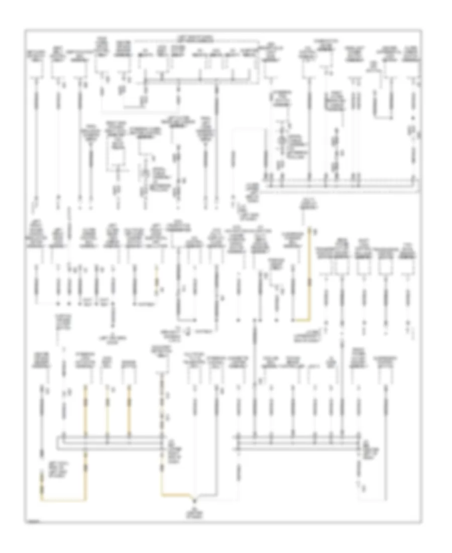
Ground Distribution Wiring Diagram (3 of 4) for Toyota Land Cruiser 2014
List of elements for Ground Distribution Wiring Diagram (3 of 4) for Toyota Land Cruiser 2014:
- (left end of dash) left cowl side j/b
- (right end of dash) right cowl side j/b
- (w/ navigation) multi- media module receiver assembly
- (w/o multi- display) clock assembly
- (w/o navigation) hazard warning signal switch assembly
- A/c control assembly
- A28
- Acc relay
- Ash receptacle light sub- assembly
- C17
- Center air bag sensor assembly
- Center differential lock switch
- Certification ecu assembly
- Cigarette lighter assembly
- Clearance warning ecu assembly
- Column)
- Combination meter assembly
- Cooling box assembly
- Curtain air bag cutoff switch
- D16
- D28
- D30
- D62
- Dcm (telematics transceiver)
- Dlc 3
- E2 (center of dash)
- E29
- E41
- E47
- E91
- El1
- Engine switch
- F56
- F58
- F60
- Fe5
- Four wheel drive control ecu
- From ground e1 (diagram 2 of 4)
- From left visor assembly (diagram 2 of 4)
- Front power outlet socket assembly
- Fg1
- Ge2
- Headlight dimmer switch assembly
- I17
- I18
- I2 (left driver's door)
- Id code box
- Ie3
- Ie5
- Ie6
- Ig1 relay 1
- Ig1 relay 2
- Ig1 relay 3
- Inverter relay
- J/c e59 (upper left end of dash)
- J/c e60 (upper right end of dash)
- J/c e62 (left end of dash)
- J/c e66 (center left of dash)
- J/c e67 (upper right end of dash)
- Left cowl side j/b (left end of dash)
- Left front door electrical key oscillator
- Left front door lock assembly
- Left front power window regulator motor assembly
- Left outer rear- view mirror assembly
- Left outer rearview mirror assembly
- Lc2
- Main body ecu
- Multi- display assembly
- Multiplex network master switch assembly
- Multiplex tilt & telescopic ecu
- Network gateway ecu
- Occupant detection ecu
- Outer mirror control ecu assembly
- Outer mirror switch assembly
- Parking assist ecu
- Pf1
- Power outlet relay
- Rear power outlet socket assembly
- Right outer rearview mirror assembly
- Seat belt control ecu
- Shift lock control ecu sub- assembly
- Spiral cable assembly (in steering e12
- Spiral cable assembly (in steering e87
- Steering control ecu
- Steering lock actuator assembly
- Steering pad switch assembly
- Steering wheel heater control assembly
- Suspension control switch
- To ground f1 (diagram 4 of 4)
- Tow bk/up relay
- Towing brake controller
- Transfer position switch
- Transmission control switch
- Ve1
- Vsc off switch
- Yaw rate sensor assembly
- Z35
- Z45
- Zi2
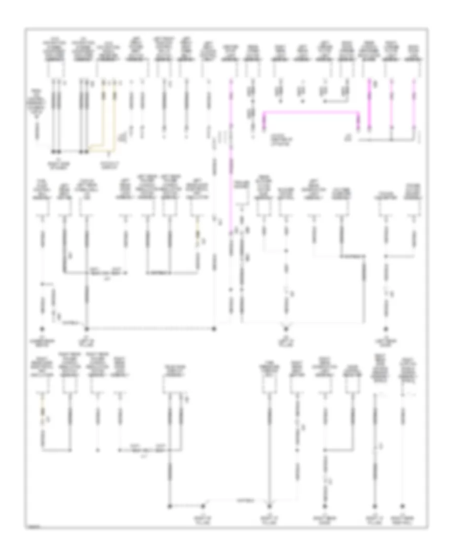
Ground Distribution Wiring Diagram (4 of 4) for Toyota Land Cruiser 2014
List of elements for Ground Distribution Wiring Diagram (4 of 4) for Toyota Land Cruiser 2014:
- (top of left rear wheelwell) j/c k28
- (w/ navigation) stereo component amplifier assembly
- (w/o navigation) radio receiver assembly
- (w/o navigation) stereo component amplifier assembly
- Back door lock assembly
- Back door opener switch assembly
- Blower motor control
- Center stop light assembly
- Door control receiver
- F1 (right side of dash)
- F55
- From a/c control assembly (diagram 3 of 4)
- Fuel pump control ecu assembly
- J/c c23
- J/c s15 (center of liftgate)
- J/c s16
- J1 (right rear door)
- J2 (left rear door)
- Jk1
- Jl1
- K1 (left "b" pillar)
- K2 (left "d" pillar)
- Kn1
- Kc1
- Kd1
- Kz1
- L1 (right "b" pillar)
- L2 (right "d" pillar)
- L3 (right "c" pillar)
- L4 (right rear roof rail)
- L40
- Left front position control ecu & switch assembly
- Left front power seat switch assembly
- Left front seat inner belt assembly
- Left license plate light assembly
- Left rear combination light assembly
- Left rear door electrical key oscillator
- Left rear door lock assembly
- Left rear light assembly
- Left rear power window regulator motor assembly
- Left rear power window regulator switch assembly
- Left rear seat heater
- Left seat climate control ecu
- Ll1
- Ld1
- Mk2
- N1 (under rear seats)
- Power outlet socket assembly
- Qm1
- Rear blower w/ fan motor sub- assembly
- Rear window defogger (back door glass)
- Rear wiper motor assembly
- Right curtain shield air bag assembly shield
- Right license plate light assembly
- Right rear combination light assembly
- Right rear door electrical key oscillator
- Right rear door lock assembly
- Right rear light assembly
- Right rear power window regulator motor assembly
- Right rear power window regulator switch assembly
- Right rear seat heater
- Right rear side air bag sensor assembly shield
- S20
- Sk1
- Television display assembly
- Tire pressure warning ecu
- Towing converter
- Trailer socket
- Voltage inverter assembly
- W/o multi display
- C14
- Zj1
- Zj2
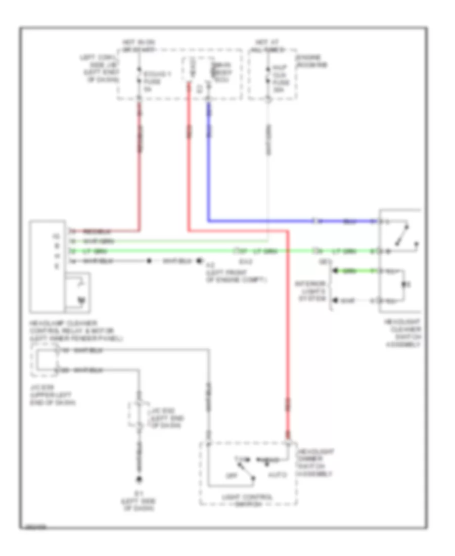
HEADLIGHTS
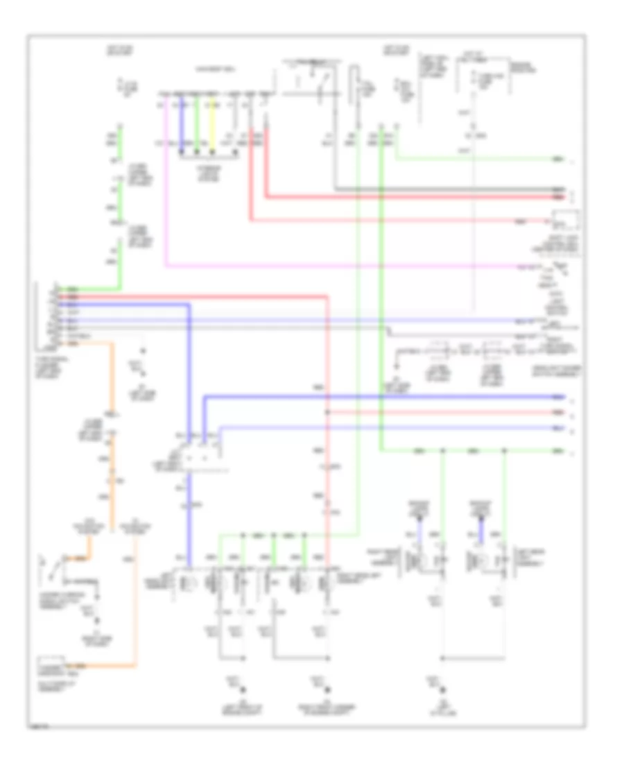
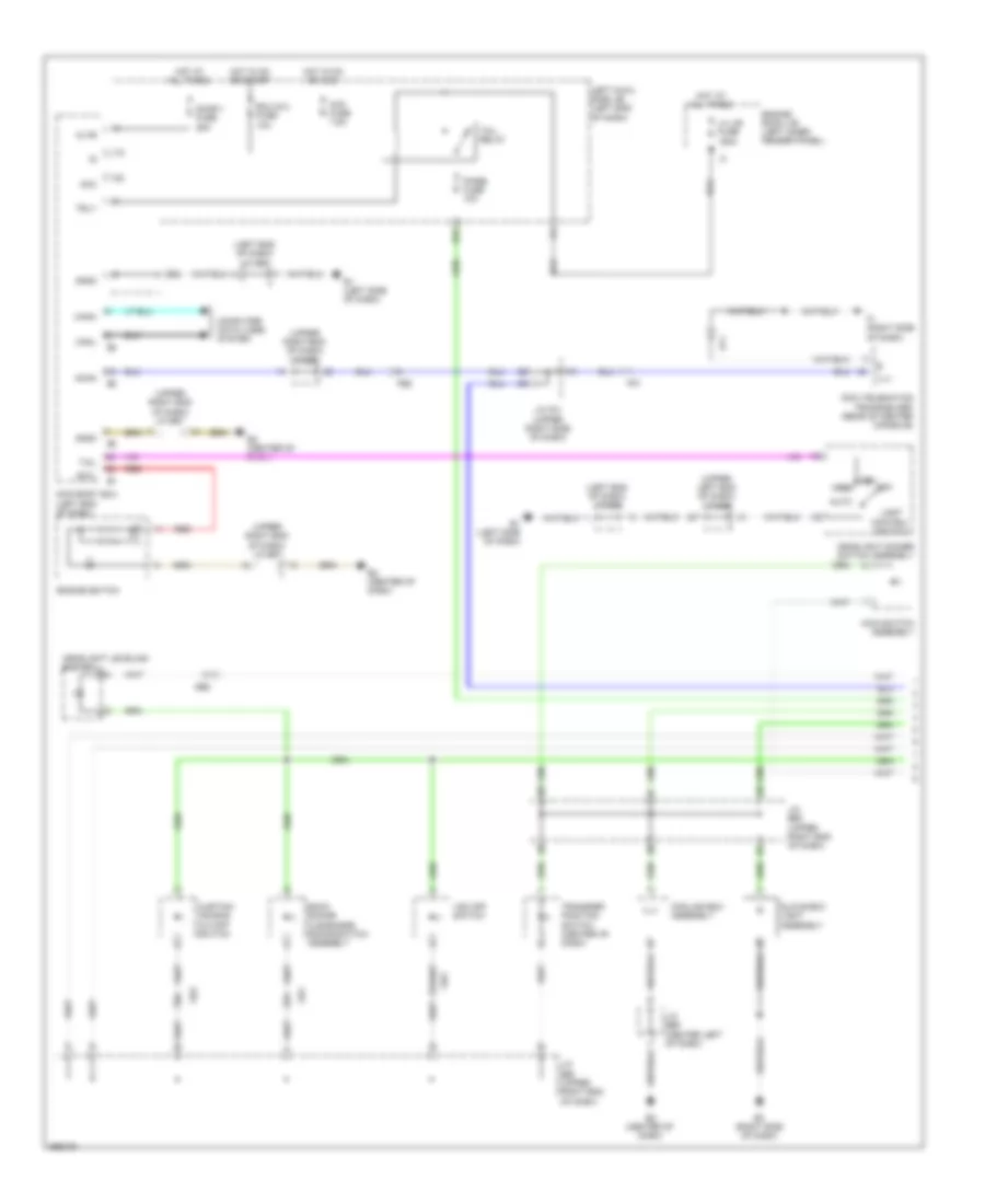
Headlights Wiring Diagram (1 of 2) for Toyota Land Cruiser 2014
List of elements for Headlights Wiring Diagram (1 of 2) for Toyota Land Cruiser 2014:
- Acc
- Acc fuse 7.5a
- Altb
- Auto
- Automatic light control sensor (center of dash)
- B13
- B16
- B18
- Bcty
- Canh
- Canl
- Cltb
- Clte
- Clts
- Computer data lines system
- D13
- D14
- D22
- D62
- Dcty
- Dim
- Dimmer switch
- Door 1 fuse 25a
- Drl
- E1 (left side of dash)
- E2 (center of dash)
- Ecu-b1 fuse 5a
- Ecu-ig 2 fuse 10a
- Engine room j/b (left inner fender panel)
- Engine room r/b
- Exterior lights system
- Fe6
- Ffgo
- Ffog
- Flash
- Fog switch
- Fr fog fuse 15a
- Gnd2
- Gnd3
- Head
- Headlight dimmer switch assembly
- High
- Hot at all times
- Hot w/ acc relay energized
- Hot w/ ig1 3 relay energized
- Hot w/ ig2 relay energized
- Hot w/ tail relay energized
- Hrly
- Interior lights system
- J/c e59 (upper left end of dash)
- J/c e62 (left end of dash)
- J/c e67 (upper right end of dash)
- Lcty
- Left cowl side j/b (left end of dash)
- Light control switch
- Low
- Main body ecu
- Main fuse 40a
- Met fuse 5a
- Off
- Parking brake switch assembly
- Pcty
- Pkb
- Rcty
- Red
- Tail
- Tail fuse 15a
- Trly
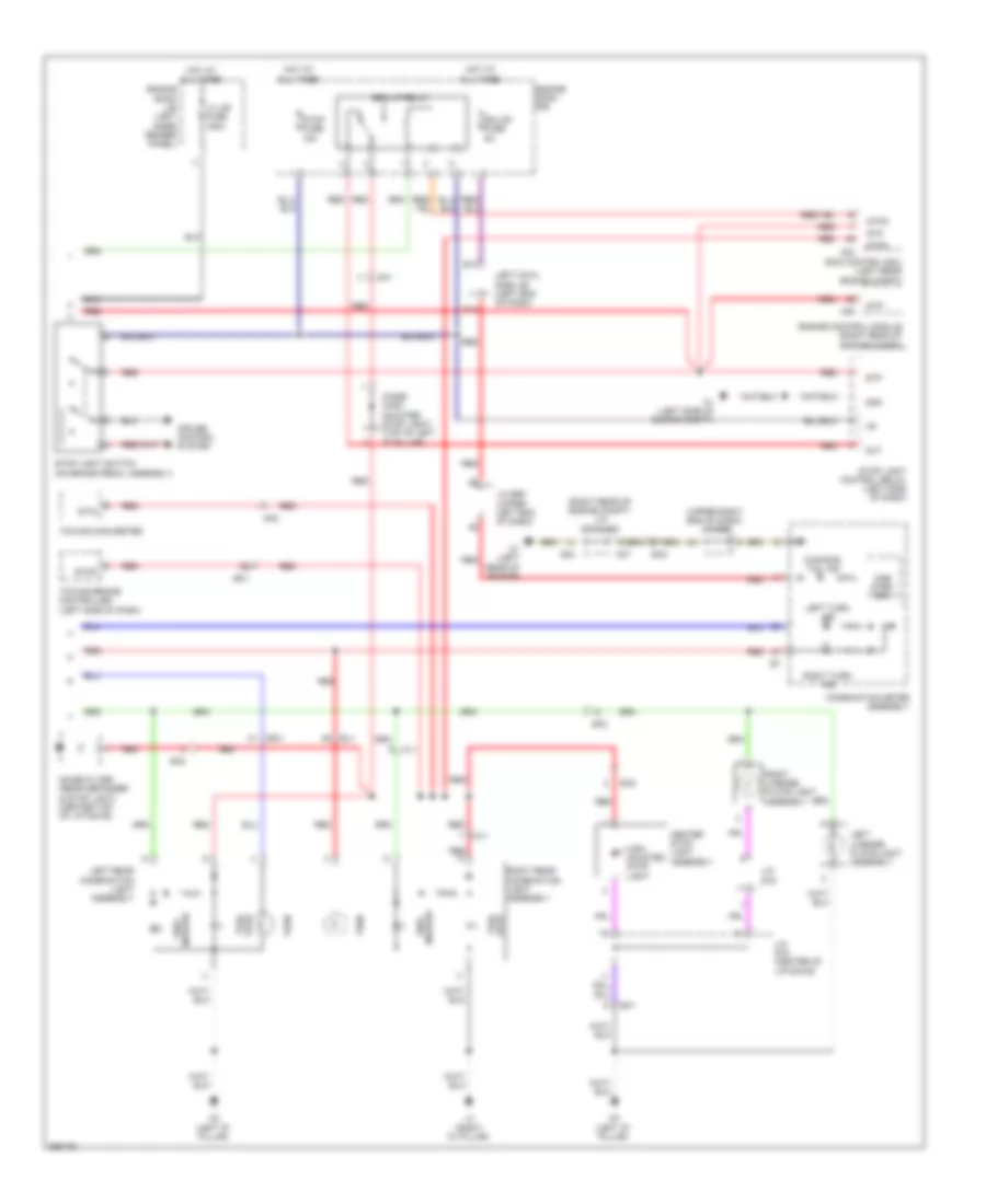
Headlights Wiring Diagram (2 of 2) for Toyota Land Cruiser 2014
List of elements for Headlights Wiring Diagram (2 of 2) for Toyota Land Cruiser 2014:
- +ig
- A2 (left front of engine compt)
- A37
- A4 (right front corner of engine compt)
- A40
- A41
- A44
- A45
- Ba1
- Beam ind
- C1 (left rear of engine)
- C52
- Can
- Canh
- Canl
- Combination meter assembly
- Computer data lines system
- Dim step one
- Drl mod relay
- Drls
- Ea1
- Ea2
- Ea3
- Engine room r/b
- Fr fog relay
- Front fog ind
- Head ind (usa)
- Head lo relay
- Hid (low)
- High
- Hlol
- Hlor
- Ig+
- J/c a37 & c52 (right rear of engine compt)
- J/c e59 (upper left end of dash)
- J/c e60 (upper right end of dash)
- Left fog light assembly
- Left headlight assembly
- Lh head fuse 15a
- Light control ecu
- Ll head fuse 15a
- Red
- Rh head fuse 15a
- Right fog light assembly
- Right headlight assembly
- Rl head fuse 15a
HORN
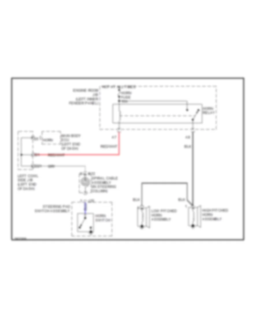
Horn Wiring Diagram for Toyota Land Cruiser 2014
List of elements for Horn Wiring Diagram for Toyota Land Cruiser 2014:
- D21
- E12
- Engine room j/b (left inner fender panel)
- High pitched horn assembly
- Horn
- Horn fuse 10a
- Horn relay
- Horn switch
- Hot at all times
- Left cowl side j/b (left end of dash)
- Low pitched horn assembly
- Main body ecu (left end of dash)
- Spiral cable assembly (in steering column)
- Steering pad switch assembly
- Z35
INSTRUMENT CLUSTER
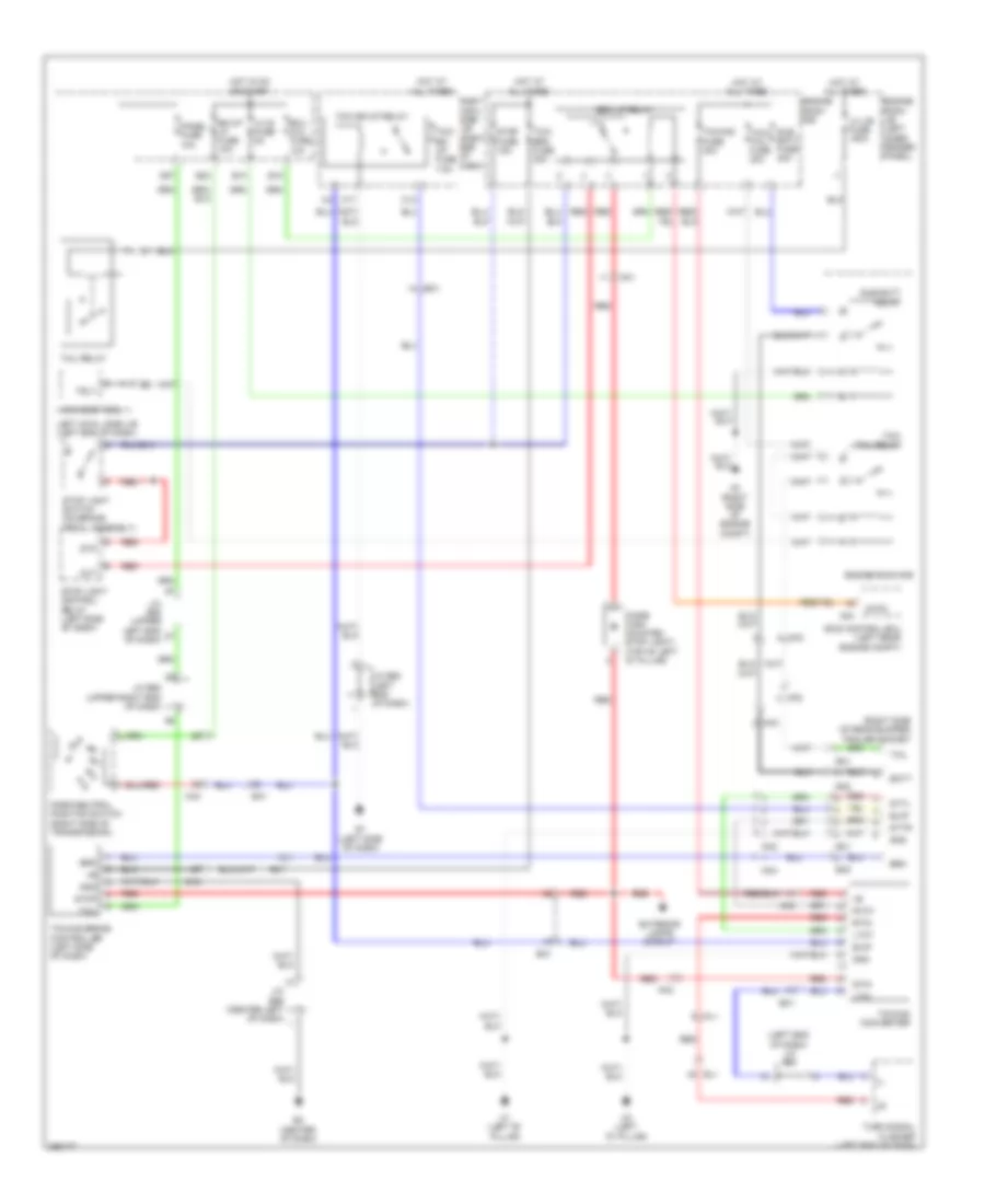
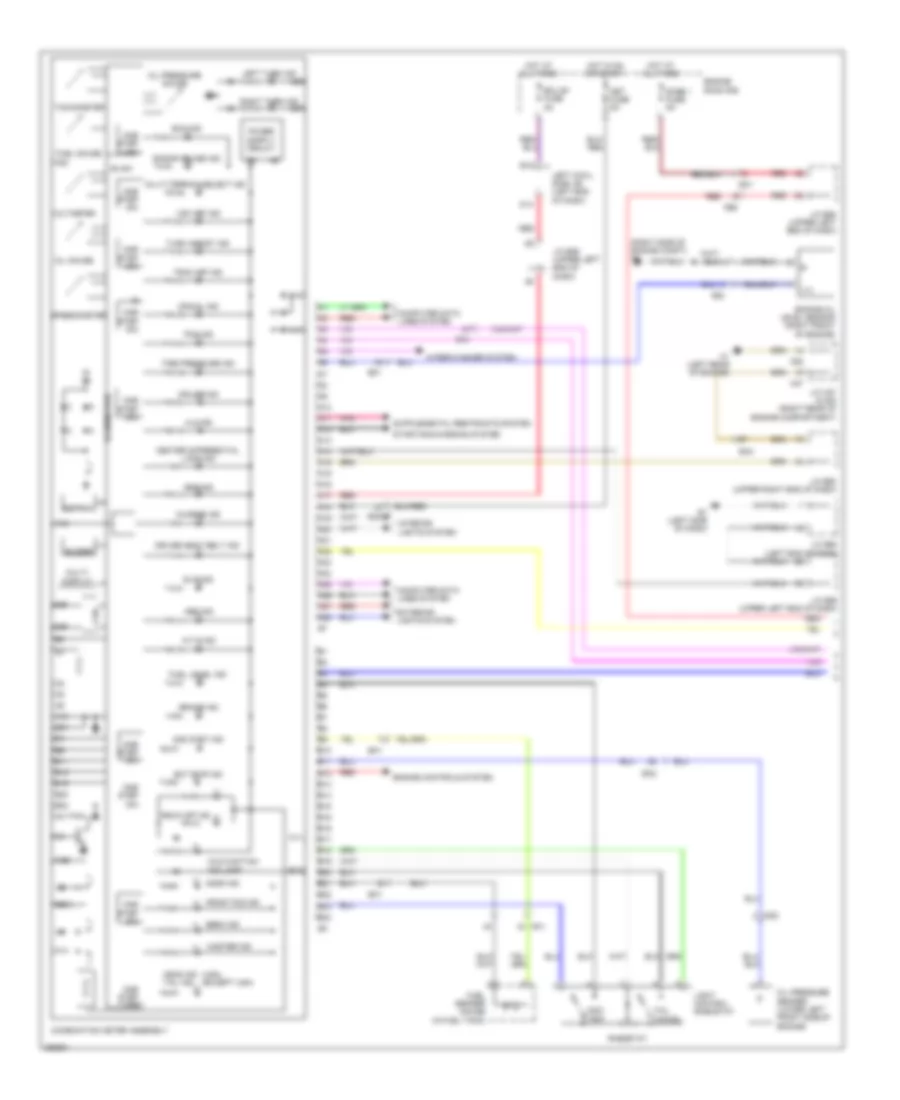
Instrument Cluster Wiring Diagram (1 of 2) for Toyota Land Cruiser 2014
List of elements for Instrument Cluster Wiring Diagram (1 of 2) for Toyota Land Cruiser 2014:
- (right side of engine compt) a3
- (usa) (except usa)
- 2nd strt ind
- 4lo ind
- A/t p ind
- A10
- A11
- A12
- A13
- A14
- A15
- A16
- A17
- A18
- A19
- A20
- A21
- A22
- A23
- A24
- A25
- A26
- A27
- A28
- A37
- Abs ind
- Ad2
- B10
- B11
- B12
- B13
- B14
- B15
- B16
- B17
- B18
- B19
- B20
- B21
- B22
- B23
- B24
- Beam ind
- Blink
- Brake ind
- Buzzer
- C1 (left rear of engine)
- C52
- Can
- Center differential lock ind
- Charge ind
- Combination meter assembly
- Computer data lines system
- Crawl ind
- Cruise ind
- D14
- Dome 1 fuse 5a
- Door ind
- Driver seat belt ind
- E1 (left side of dash)
- Ea1
- Ea2
- Ea3
- Eco ind
- Ect pwr ind
- Ecu b1 fuse 5a
- Eeprom
- Ek1
- Engine controls system
- Engine oil level sensor (right front of engine)
- Engine room r/b
- Exterior lights system
- Fe6
- Front fog ind
- Fuel gauge
- Fuel level ind
- Fuel sender gauge (in fuel tank)
- Head ind tail ind
- Hot at all times
- Hot in on or start
- Ig +b
- Ig+
- Illumination
- Interior lights system
- J/c a37 & c52 (right rear of engine compartment)
- J/c e58 (upper left end of dash)
- J/c e59 (upper left end of dash)
- J/c e60 (upper right end of dash)
- J/c e62 (left end of dash)
- Left cowl side j/b (left end of dash)
- Left turn ind
- Light control rheostat
- Lvl
- Malfunction ind lamp
- Master ind
- Met fuse 5a
- Multi- display
- Multi-terrain select ind
- Nk1
- Odo/ trip
- Oil gauge
- Oil pressure gauge
- Oil pressure sender (lower left front side of engine)
- One step dim
- Pcs ind
- Pnk
- Radar cruise ind
- Red
- Rheostat
- Right turn ind
- Rsca off ind
- Slip ind
- Speedometer
- Srs ind
- Starting/charging system
- Tachometer
- Tail cancel
- Tire pressure ind
- Trac off ind
- Turn assist ind
- Voltmeter
- Vsc off ind
- Wiper/washer system
Instrument Cluster Wiring Diagram (2 of 2) for Toyota Land Cruiser 2014
List of elements for Instrument Cluster Wiring Diagram (2 of 2) for Toyota Land Cruiser 2014:
- (right side of dash) f1
- A1 (left side of engine compt)
- A24
- A38
- Acan
- Acc
- Acc fuse 7.5a
- Anti theft system
- Back door lock assembly
- Bcty
- Brake fluid level warning switch (brake master cylinder reservoir assembly) (master cylinder reservoir)
- C53
- Canh
- Canl
- Clock assembly
- Computer data lines system
- Courtesy
- D22
- Dcm (telematics transceiver) (rear of center console)
- Dcty
- Disp
- E12
- Ea3
- Ecu-ig 2 fuse 10a
- Efi engine coolant temperature sensor (top left front of engine)
- Ek2
- Engine control module (right rear of engine compt)
- Etha
- F18
- F19
- F55
- F58
- F60
- Fe1
- Fe3
- Fe4
- Fe5
- Fe6
- Fl2
- Fg1
- Gnd
- Hot in on or acc
- Hot in on or start
- Ig+
- J/c e58 (upper left end of dash)
- J/c e59 (upper left end of dash)
- J/c e60 (upper right end of dash)
- J/c e61 (upper right end of dash)
- J/c f20 (upper right side of dash)
- J/c f21 (upper right side of dash)
- J/c s15 (center of liftgate)
- J/c s16
- K2 (left "d" pillar)
- Lapl
- Lbl
- Lcty
- Left cowl side j/b (left end of dash)
- Left front door courtesy light switch assembly
- Left rear door courtesy light switch assembly
- Left steering switch
- Main body ecu
- Multi-display assembly & multi-media module receiver assembly
- P-ab
- Paon
- Parking brake switch assembly
- Pbew
- Pcty
- Pf1
- Pkb
- Pnk
- Radio receiver assembly
- Rcty
- Red
- Right front door courtesy light switch assembly
- Right rear door courtesy light switch assembly
- Right steering switch
- Sk1
- Skid control ecu (left rear engine compt)
- Sp1
- Spd
- Spdp
- Spiral cable sub assembly (in steering column)
- Steering pad switch assembly
- Stereo component amplifier assembly (under driver's seat)
- Swg
- Thw
- W/ multi- display
- W/ multi-display
- W/ navigation
- W/o multi- display
- W/o multi-display
- W/o navigation
- Z35
INTERIOR LIGHTS
Courtesy Lamps Wiring Diagram (1 of 2) for Toyota Land Cruiser 2014
List of elements for Courtesy Lamps Wiring Diagram (1 of 2) for Toyota Land Cruiser 2014:
- (front passenger's door) right front door lock assembly
- (left "b" pillar)
- (left end of dash) j/c e62
- (left rear door) left rear door lock assembly
- (right passenger's door)
- Acc
- Altb
- Bcty
- Canh
- Canl
- Computer data lines system
- D51
- D62
- Dcty
- Diode (left front door courtesy switch)
- Diode (right front door courtesy switch)
- Diode (right rear door courtesy switch)
- Dome 1 fuse 5a
- Dome 2 fuse 7.5a
- Door 1 fuse 25a
- E1 (left side of dash)
- E2 (center of dash)
- E58
- E59
- E61
- Ea1
- Ecu-ig 2 fuse 10a
- Ek2
- El1
- Engine room r/b
- Engine switch
- Fe3
- Fe4
- Fl2
- Fuse 7.5a
- Gnd2
- Gnd3
- Hot at all times
- Hot in on or acc
- Hot in on or start
- Ie2
- Ie3
- Ie6
- Ile
- J/c e58 & e59 (upper left end of dash) e58
- J/c e61 (upper right end of dash)
- J/c e67 (upper right end of dash)
- Jk1
- Jl1
- Lcty
- Left cowl side j/b (left end of dash)
- Left front door courtesy light assembly
- Left front door courtesy light switch assembly
- Lswd
- Lswl
- Lswp
- Lswr
- Main body ecu (left end of dash)
- Pcty
- Rcty
- Re2
- Red
- Right front door courtesy light assembly
- Right front door courtesy light switch assembly
- Right rear door courtesy light assembly
- Right rear door courtesy light switch assembly
- Swil
- Unlock detection
Courtesy Lamps Wiring Diagram (2 of 2) for Toyota Land Cruiser 2014
List of elements for Courtesy Lamps Wiring Diagram (2 of 2) for Toyota Land Cruiser 2014:
- (center of liftgate) j/c s15
- (right "b" pillar)
- (right rear of engine compt) j/c c52
- (right side of transmission)
- +b1
- +b3
- A38
- B23
- Back door lock assembly
- Bk/up lp fuse 10a
- C53
- Ca3
- Canh
- Canl
- Computer data lines system
- Courtesy
- Cty
- Diode (left rear door courtesy switch)
- Dome light
- Dome light map light
- E1 (left side of dash)
- Ek2
- El1
- Engine control module (right rear of engine compt)
- Hot in on or start
- I2 (left driver's door)
- Ie6
- Illb
- J/c s16
- Jk1
- Jl1
- K2 (left "d" pillar)
- Left cowl side j/b (left end of dash)
- Left front door lock assembly (driver's door)
- Left rear door courtesy light assembly
- Left rear door courtesy light switch assembly
- Left visor assembly
- Map light dome light
- Overhead module (front headliner)
- Park/neutral position switch p
- Pnk
- Red
- Rgnd
- Right rear door lock assembly (right rear door)
- Right visor assembly
- Rill
- Room light assembly 1
- Room light assembly 2 (w/o rear seat entertainment system)
- Room light assembly 3
- Rrvt
- Sk1
- Unlock detection
- W/ rear seat entertainment system
- W/o rear seat entertainment system
Instrument Illumination Wiring Diagram (1 of 2) for Toyota Land Cruiser 2014
List of elements for Instrument Illumination Wiring Diagram (1 of 2) for Toyota Land Cruiser 2014:
- (left end of dash) j/c e62
- (upper left end of dash) j/c e59
- (upper right end of dash) j/c e60
- (upper right end of dash) j/c e67
- Acan
- Acc
- Acc fuse 7.5a
- Altb
- Auto
- Back sonar/ clearance sonar switch assembly
- Canh
- Canl
- Computer data lines system
- Cooling box assembly
- Curtain air bag cutoff switch
- D57
- D62
- Dcm (telematics transceiver) (rear of center console)
- Door 1 fuse 25a
- E1 (left side of dash)
- E2 (center of dash)
- E3 (right side of dash)
- Ecu-ig 2 fuse 10a
- Engine room j/b (left inner fender panel)
- Engine switch
- F1 (right side of dash)
- Fe5
- Ge1
- Ge2
- Glove box light assembly
- Gnd2
- Gnd3
- Head
- Headlight dimmer switch assembly
- Headlight leveling switch
- Hot at all times
- Hot in on or acc
- Hot in on or start
- Ill+
- J/c e60 (upper right end of dash)
- J/c e66 (center left of dash)
- J/c f21 (upper right side of dash)
- Left cowl side j/b (left end of dash)
- Lh j/b fuse 150a
- Light control switch
- Main body ecu (left end of dash)
- Main switch assembly
- Off
- Panel fuse 10a
- Pf1
- Red
- Swil
- Tail
- Tail relay
- Transfer position switch (center of dash)
- Trly
- Vsc off switch
Instrument Illumination Wiring Diagram (2 of 2) for Toyota Land Cruiser 2014
List of elements for Instrument Illumination Wiring Diagram (2 of 2) for Toyota Land Cruiser 2014:
- (front headliner) overhead module
- (left end of dash) j/c e62
- (left side of dash) e1
- (right rear of engine compt) j/c a37 & c52
- (right side of dash) f1
- (upper left end of dash) j/c e58
- (upper left end of dash) j/c e59
- (upper right end of dash) j/c e60
- A/b
- A/c control assembly (w/o navigation)
- A/c control assembly 2
- A37
- Adim
- Ash receptacle light sub- assembly
- C1 (left rear of engine)
- C52
- Can
- Cancel tail
- Center differ- -ential lock switch
- Cigarette lighter illumination assembly
- Combination meter assembly
- Computer data lines system
- Dim
- E1 (left side of dash)
- E12
- E58
- E59
- Ea2
- Ea3
- Engine room r/b
- F1 (right side of dash)
- F19
- F58
- Fe1
- Fe4
- Ge1
- Ge2
- Gill
- Gnd
- Gnd1
- Hazard warning signal switch assembly (w/o navigation)
- Headlight cleaner switch assembly
- Hot in on or start
- Ill
- Ill+
- Ill-
- J/c e58 & e59 (upper left end of dash)
- J/c e59 (upper left end of dash)
- J/c e61 (upper right end of dash)
- J/c e62 (left end of dash)
- Left steering switch
- Left temperature control switch assembly
- Light control rheostat
- Met fuse 5a
- Multi-display assembly (w/ navigation)
- Multi-media module receiver assembly
- Odo/ trip
- One
- Outer mirror switch assembly
- Radio receiver assembly
- Red
- Rf1
- Rheostat
- Right steering switch
- Right temperature control switch assembly
- Seat heater switch
- Spiral cable sub assembly (in steering column)
- Steering heater switch
- Steering pad switch assembly
- Step
- Suspension control switch
- Swg
- Trans- mission control switch (center console)
- Ve1
- W/ navigation
- W/o navigation
- Z35
MEMORY SYSTEMS
Memory Mirrors Wiring Diagram for Toyota Land Cruiser 2014
List of elements for Memory Mirrors Wiring Diagram for Toyota Land Cruiser 2014:
- (left driver's door) i2
- (upper right end of dash) j/c e61
- Acc
- Acc fuse 7.5a
- Altb
- Am1
- Am2
- Am2 fuse 5a
- B20
- Batb
- Canh
- Canl
- Cann
- Canp
- Computer data lines system
- D54
- D62
- Dcb+
- Dcv+
- Dcv-
- Defogger system
- Dgnd
- Door 1 fuse 25a
- Door 2 fuse 25a
- E1 (left side of dash)
- E2 (center of dash)
- Ea2
- Ecu-ig 2 fuse 10a
- Engine room r/b
- Exterior lights system
- Ge2
- Gnd
- Gnd2
- Gnd3
- Heater mirror
- Hot at all times
- Hot in acc or on
- Hot in on or acc
- Hot in on or start
- Hslr
- Hsrr
- I17
- I18
- I2 (left driver's door)
- Ie1
- Ie2
- Ie4
- Ie5
- Interior lights system
- Ix1
- J/c e59 (upper left end of dash)
- J/c e60 (upper right end of dash)
- J/c e61 (upper right end of dash)
- J/c e62 (left end of dash)
- J/c e67 (upper right end of dash)
- Le1
- Left cowl side j/b (left end of dash)
- Left outer rear view mirror assembly
- Left seat memory switch
- Lvc
- M+l
- M+r
- Main body ecu (left end of dash)
- Mhl
- Mhr
- Mir fuse 15a
- Mirb
- Mire
- Mirror heater
- Mirrors system
- Mirs
- Mry
- Msw
- Mswe
- Mvl
- Mvr
- Navigation system
- Nca
- Outer mirror control ecu (driver's door)
- Outer mirror switch assembly
- Re1
- Red
- Ret
- Right outer rear view mirror assembly
- Rvc
- Scb+
- Scv+
- Scv-
- Set
- Sgnd
- Turn
- Vr1
- Vsr
- Vssr
Memory Power Tilt & Power Telescopic Wiring Diagram for Toyota Land Cruiser 2014
List of elements for Memory Power Tilt & Power Telescopic Wiring Diagram for Toyota Land Cruiser 2014:
- B13
- Canh
- Canl
- Cann
- Canp
- Computer data lines system
- D14
- D34
- D56
- E1 (left side of dash)
- E2 (center of dash)
- Ecu b1 fuse 5a
- Ecu-ig 1 fuse 5a
- Ecub
- Engine room r/b
- Gnd
- Headlight dimmer switch assembly
- Hot at all times
- Hot in on or start
- I18
- Ix1
- J/c e59 (upper left end of dash)
- J/c e60 (upper right end of dash)
- J/c e61 (upper right end of dash)
- Left cowl side j/b (left end of dash)
- Left seat memory switch
- Mry
- Msw
- Mswe
- Multiplex tilt & telescopic ecu (behind left side of dash)
- Outer mirror control ecu (driver's door)
- Pnk
- Power tilt motor (left side of dash)
- Red
- Sensor telescopic
- Sensor tilt
- Set
- Shrink opic telesc-
- Stretch telescopic
- Telescopic motor
- Tem+
- Tem-
- Tes
- Ti & te fuse 15a
- Tilt & telescopic switch
- Tilt down
- Tilt motor
- Tilt up
- Tim+
- Tim-
- Tis
- Vce
- Vci
Memory Seat Wiring Diagram for Toyota Land Cruiser 2014
List of elements for Memory Seat Wiring Diagram for Toyota Land Cruiser 2014:
- Ak2
- Canh
- Canl
- Computer data lines system
- Ecu-b2 fuse 5a
- Ek1
- Ek2
- Engine room r/b
- Fr p/ seat lh fuse 30a
- Frv+
- Frv-
- Gnd
- Hot at all times
- I18
- Ix1
- J/c c23
- K1 (left "b" pillar)
- Kc1
- Left cowl side j/b (left end of dash)
- Left front position control ecu & switch assembly
- Left front power seat switch assembly
- Left seat memory switch
- Lft+
- Lft-
- Lumbar support
- Mpx1
- Mpx2
- Mry
- Mswe
- Outer mirror control ecu (driver's door)
- Pnk
- Power seat motor (driver's seat front vertical control) (driver's seat)
- Power seat motor (driver's seat lifter control) (driver's seat)
- Power seat motor (driver's seat lumbar support control)
- Power seat motor (driver's seat reclining control) (lower right driver's seat back)
- Power seat motor (driver's seat slide control) (driver's seat)
- Rcl+
- Rcl-
- Red
- Set
- Sld+
- Sld-
- Sysb
- C14
- C15
NAVIGATION
Navigation Wiring Diagram (1 of 5) for Toyota Land Cruiser 2014
List of elements for Navigation Wiring Diagram (1 of 5) for Toyota Land Cruiser 2014:
- (upper left end of dash) j/c e58
- (upper right side of dash) j/c f21
- +b1
- Acc1
- C19
- Ca+
- Canh
- Canl
- Cb+
- Cgnd
- Computer data lines system
- Cv+
- Cv-
- D22
- Ea1
- Ek2
- F1 (right side of dash)
- F56
- F57
- F58
- F64
- F66
- Fe3
- Fe5
- Fe6
- Ff1
- Gnd1
- Gps antenna
- Gvif
- Hot at all times
- Ill+
- Ill-
- Interior lights system
- Left cowl side j/b (left end of dash)
- Macc
- Min+
- Min-
- Multimedia module receiver assembly
- Nca
- Parking assist ecu (center right of dash)
- Parking brake switch assembly
- Pkb
- Pnk
- Rear television camera assembly (w/o multi terrain monitor)
- Red
- Rev
- Rf1
- Right cowl side j/b (right end of dash)
- Sdars antenna
- Sgnd
- Sk1
- Sns2
- Spd
- Sw1
- Sw2
- Swg
- Tv fuse 10a
- Tx+
- Tx-
- Tx1+
- Tx1-
- Tx3+
- Tx3-
- Uind
- Upsw
- Vmtf
Navigation Wiring Diagram (2 of 5) for Toyota Land Cruiser 2014
List of elements for Navigation Wiring Diagram (2 of 5) for Toyota Land Cruiser 2014:
- (right side of transmission)
- (upper right side of dash) j/c f20
- (upper right side of dash) j/c f21
- +b2
- Acc
- Acc fuse 7.5a
- Agnd
- Air
- Air conditioning system
- Al1
- Antenna
- Aron
- B23
- Bgnd
- Bk/up lp fuse 10a
- Ca3
- Door locks system
- E12
- Ecu-ig 1 fuse 5a
- Engine room r/b
- Exterior lights system
- F1 (right side of dash)
- F46
- F60
- F63
- F65
- Fe4
- Fe5
- Fe6
- Gnd1
- Gvif
- Haz
- Hot at all times
- Hot w/ acc relay energized
- Hot w/ ig1 1 relay energized
- Hot w/ ig1 2 relay energized
- Ill+
- Ill-
- Interior lights system
- Left cowl side j/b (left end of dash)
- Left steering switch
- Mode
- Multi-display assembly
- Nca
- Off hook
- On hook
- Park/ neutral position switch
- Pbew
- Pnk
- Red
- Right steering switch
- Rse fuse 7.5a
- Secu
- Seek+
- Seek-
- Spiral cable sub-assembly (in steering column)
- Steering pad switch assembly
- Tec+
- Tec-
- Tes+
- Tes-
- Tx+
- Tx-
- Uind
- Upsw
- Vmti
- Voice
- Vol+
- Vol-
- Warning systems
- Z35
Navigation Wiring Diagram (3 of 5) for Toyota Land Cruiser 2014
List of elements for Navigation Wiring Diagram (3 of 5) for Toyota Land Cruiser 2014:
- +b2
- Adpg
- Agnd
- Alo
- Aro
- Asgn
- Auxo
- Ef2
- Entertainment system
- F59
- F61
- F67
- Fe3
- Ff2
- Fl1
- Fl2
- Fl6
- Gnd
- Gnd2
- Headphone terminal
- Hp1l
- Hp1r
- Hp2l
- Hp2r
- L1 (right "b" pillar)
- L40
- L41
- Mi+
- Mi-
- Mo+
- Mo-
- Multimedia module receiver assembly
- Nca
- Nts4
- Ntsg
- Ntso
- Pf1
- Pf2
- Red
- Sgn1
- Sgn2
- Sgn4
- Sld2
- Sld4
- Sld5
- Sld6
- Sldi
- Sldo
- Stereo jack adapter assembly 1
- Television display assembly
- Udi+
- Udi-
- Ugd1
- Ujsg
- Upo
- Us1+
- Us1-
- Usv1
- Va-
- Val+
- Val-
- Var+
- Vmtr
- Vv+
- Vv-
- W/ rear seat
- W/o rear seat entertainment system
- Wui
- Wuo
- Fe1
- Fe2
Navigation Wiring Diagram (4 of 5) for Toyota Land Cruiser 2014
List of elements for Navigation Wiring Diagram (4 of 5) for Toyota Land Cruiser 2014:
- (front headliner) overhead module
- (rear of center console) (w/ safety connect) dcm (telematics transceiver)
- Acc
- Ek2
- Fe1
- Fe7
- Ff1
- Fl1
- Front speaker assembly 4
- Ie3
- Ie6
- Jl2
- Left front speaker assembly 1
- Left rear header speaker assembly
- Mci+
- Mci-
- Mco+
- Mco-
- Mcvd
- Mi1+
- Mic-
- Microphone amplifier
- Mute
- Nca
- Pf3
- Pnk
- Red
- Rf1
- Right front speaker assembly 1
- Right front speaker assembly 2
- Right front speaker assembly 3
- Right rear speaker assembly 3
- Right rear speaker set
- Rld+
- Rld-
- Sgnd
- Sk2
- Sns2
- Spi+
- Spi-
- Spo+
- Spo-
- Twr+
- Twr-
- W/ safety connect
- W/o safety connect
- Wf+
- Wf-
Navigation Wiring Diagram (5 of 5) for Toyota Land Cruiser 2014
List of elements for Navigation Wiring Diagram (5 of 5) for Toyota Land Cruiser 2014:
- +b2
- A24
- Amp1 fuse 30a
- Amp2 fuse 30a
- Combination meter assembly
- Ctr+
- Ctr-
- Ea1
- Ea2
- Ek2
- Engine room r/b
- F1 (right side of dash)
- F55
- F62
- Fe5
- Fe6
- Fe7
- Fl+
- Fl-
- Fl1
- Fr+
- Fr-
- Gnd
- Gnd2
- Hot at all times
- J/c e58 (upper left end of dash)
- J/c f20 (upper right side of dash)
- Jk2
- Left front speaker assembly
- Left front speaker assembly 3
- Left rear speaker assembly 3
- Left rear speaker set
- Mi+
- Mi-
- Mo+
- Mo-
- Nca
- Pnk
- R-l+
- R-l-
- R-r+
- R-r-
- Red
- Right rear header speaker assembly
- Rrd+
- Rrd-
- Sk2
- Skid control ecu (left rear engine compt)
- Sl+
- Sl-
- Sldi
- Sldo
- Spd
- Sr+
- Sr-
- Stereo component amplifier (under driver's seat)
- Tmut
- Twl+
- Twl-
- W/ box speaker assembly 1
- Wf+
- Wf-
- Wf1+
- Wf1-
- Wf2+
- Wf2-
- Wfl+
- Wfl-
- Wfr+
- Wfr-
- Wui
- Wuo
Parking Assistant Wiring Diagram, with Multi-terrain Monitor (1 of 2) for Toyota Land Cruiser 2014
List of elements for Parking Assistant Wiring Diagram, with Multi-terrain Monitor (1 of 2) for Toyota Land Cruiser 2014:
- (right side of dash) f1
- Aa3
- Acc
- Acc fuse 7.5a
- Ae3
- Ba1
- Bbz
- Bcb+
- Bcv+
- Bcv-
- Bgnd
- Blsw
- Canh
- Canl
- Cb+
- Cgnd
- Computer data lines system
- Csb1
- Csb2
- Csg1
- Csg2
- Cssw
- Cv+
- Cv-
- D56
- Dcb+
- Dcv+
- Dcv-
- Dgnd
- Ea2
- Ecu-ig 1 fuse 5a
- Engine room r/b
- F56
- F57
- F60
- F63
- F64
- F65
- F66
- F85
- Fe3
- Fe5
- Fe6
- Fl1
- Ge2
- Gnd1
- Gvif
- Hot at all times
- Hot w/ acc relay energized
- Hot w/ ig1 1 relay energized
- J/c e61 (upper right end of dash)
- J/c f20 (upper right side of dash)
- J/c f21 (upper right side of dash)
- Kl1
- Left cowl side j/b (left end of dash)
- Left ultrasonic sensor 1 (left front of bumper)
- Left ultrasonic sensor 2 (rear bumper)
- Left ultrasonic sensor 3 (rear bumper)
- Lin1
- Lin2
- Main body ecu (left end of dash)
- Mpos
- Msdl
- Multi-display assembly
- Multi-media module receiver assembly
- Ok1
- Outer mirror switch assembly
- Parking assist ecu (center right of dash)
- Pnk
- Rad 1 fuse 10a
- Red
- Ret
- Right ultrasonic sensor 1 (right front bumper)
- Right ultrasonic sensor 2 (rear bumper)
- Right ultrasonic sensor 3 (rear bumper)
- Scb+
- Scv+
- Scv-
- Sgnd
- Shield
- Tx+
- Tx-
- Tx1+
- Tx1-
- Tx3+
- Tx3-
Parking Assistant Wiring Diagram, with Multi-terrain Monitor (2 of 2) for Toyota Land Cruiser 2014
List of elements for Parking Assistant Wiring Diagram, with Multi-terrain Monitor (2 of 2) for Toyota Land Cruiser 2014:
- (right side of transmission) park/neutral position switch
- A37
- A38
- B23
- Back sonar or clearance switch assembly
- Bcb+
- Bcv+
- Bcv-
- Bgnd
- Bk/up lp fuse 10a
- C1 (left rear of engine)
- C52
- C53
- Ca3
- Can
- Canh
- Canl
- Cb+
- Cgnd
- Clearance warning buzzer 1
- Combination meter assembly
- Computer data lines system
- Cv+
- Cv-
- Dcb+
- Dcv+
- Dcv-
- Dgnd
- Ea1
- Ea2
- Ea3
- Ek2
- Engine compt)
- Engine control module (right rear of engine compt)
- Engine room r/b
- Fe1
- Fe3
- Fe7
- Front television camera assembly (center of front grille)
- Ge1
- Hot w/ ig1 2 relay energized
- Hot w/ ig2 relay energized
- Ie1
- Ie4
- Interior lights system
- J/c a37 & c52 (right rear of
- J/c c52 (right rear of engine compt)
- J/c e60 (upper right end of dash)
- Left cowl side j/b (left end of dash)
- Left outer rearview mirror assembly
- Main switch assembly
- Master ind
- Met fuse 5a
- Multi display
- Pnk
- Rear television camera assembly
- Red
- Right outer rearview mirror assembly
- Scb+
- Scv+
- Scv-
- Sgnd
- Shield
- Sk1
- Sonar switch
Parking Assistant Wiring Diagram, without Multi-terrain Monitor for Toyota Land Cruiser 2014
List of elements for Parking Assistant Wiring Diagram, without Multi-terrain Monitor for Toyota Land Cruiser 2014:
- (right side of dash) f1
- A37
- A38
- Aa3
- Ae3
- B23
- Ba1
- Back sonar or clearance sonar switch assembly
- Bbz
- Bk/up lp fuse 10a
- Bof
- Bor
- C1 (left rear of engine)
- C52
- C53
- Ca3
- Can
- Canh
- Canl
- Clearance warning buzzer 1
- Clearance warning ecu (center of dash)
- Combination meter assembly
- Computer data lines system
- Csg1
- Csg2
- Cssw
- D56
- Ea2
- Ea3
- Ecu-ig 1 fuse 5a
- Engine compt)
- Engine control module (right rear of engine compt)
- Engine room r/b
- Fe1
- Fe3
- Fe6
- Fl1
- Ge1
- Gnd1
- Hot in on or start
- Interior lights system
- J/c a37 & c52 (right rear of
- J/c c52 (right rear of engine compt)
- J/c e60 (upper right end of dash)
- J/c e61 (upper right end of dash)
- J/c f21 (upper right side of dash)
- Kl1
- Left cowl side j/b (left end of dash)
- Left ultrasonic sensor 1 (left front of bumper)
- Left ultrasonic sensor 2 (rear bumper)
- Left ultrasonic sensor 3 (rear bumper)
- Lin1
- Lin2
- Master ind
- Met fuse 5a
- Msdl
- Multi display
- N r
- Ok1
- Park/neutral position switch (right side of transmission)
- Pnk
- Red
- Right ultrasonic sensor 1 (right front bumper)
- Right ultrasonic sensor 2 (rear bumper)
- Right ultrasonic sensor 3 (rear bumper)
- Sonar switch
Telematics Wiring Diagram for Toyota Land Cruiser 2014
List of elements for Telematics Wiring Diagram for Toyota Land Cruiser 2014:
- (center rear of roof) telephone antenna
- (under driver's seat) stereo component amplifier
- A24
- Acc
- Acc fuse 7.5a
- B15
- Backup battery (mayday battery) (rear of center console)
- Bbi+
- Bbi-
- Bbo+
- Bbo-
- Btr1
- Btr2
- Combination meter assembly
- Computer data lines system
- Ctr1
- Ctr2
- D17
- Dcm (telematics transceiver) (rear of center console)
- E1 (left side of dash)
- Ea1
- Engine room r/b
- F1 (right side of dash)
- F18
- F55
- Fe5
- Fe6
- Fe7
- Fr+
- Fr-
- Gnd3
- Gnd9
- Gps antenna
- Gsw
- Hot at all times
- Hot in on or acc
- Hot in on or start
- Ig2
- Ign fuse 10a
- Ill+
- Ind1
- Ind2
- Interior lights system
- J/c e58 (upper left end of dash)
- J/c e60 (upper right end of dash)
- J/c e61 (upper right end of dash)
- J/c f20 (upper right side of dash)
- Left cowl side j/b (left end of dash)
- Mci+
- Mci-
- Mco+
- Mco-
- Mcvd
- Mute
- Nca
- Overhead module (front headliner)
- Pf1
- Pf2
- Pf3
- Pnk
- Pe1
- Red
- Rf1
- Right cowl side j/b (right end of dash)
- Right front speaker assembly 2
- Right front speaker assembly 3
- Sgnd
- Sig-
- Sig1
- Sil
- Skid control ecu (left rear engine compt)
- Sos switch
- Sound systems
- Sp1
- Spdp
- Spi+
- Spi-
- Spo+
- Spo-
- Tel fuse 5a
- Tmut
- Twr+
- Twr-
- W/ navigation system
- W/o navigation system
PASSIVE RESTRAINTS
Passive Restraints Wiring Diagram for Toyota Land Cruiser 2014
List of elements for Passive Restraints Wiring Diagram for Toyota Land Cruiser 2014:
- A3 (right side of engine compt)
- Al1
- Buckle switch
- C18
- D55
- El1
- Hot in on or start
- J/c c12
- J/c c23
- J/c e58 (upper left end of dash)
- J/c e59 (upper left end of dash)
- K1 (left "b" pillar)
- Kc1
- Left cowl side j/b (left end of dash)
- Left front seat rdc inner belt assembly
- Left front tension reducer
- Lh-ig fuse 5a
- Lc1
- Right front seat rdc inner belt assembly
- Right front tension reducer
POWER DISTRIBUTION
Power Distribution Wiring Diagram (1 of 3) for Toyota Land Cruiser 2014
List of elements for Power Distribution Wiring Diagram (1 of 3) for Toyota Land Cruiser 2014:
- (left end of dash) left cowl side j/b
- (left inner fender panel) engine room j/b
- 4wd fuse 20a
- A/c ig fuse 10a
- A/pump fuse 50a
- Abs 1 fuse 50a
- Abs 2 fuse 30a
- Acc
- Acc fuse 7.5a
- Acc relay
- Accd
- Air conditioning system
- Air conditioning, anti-lock brakes, instrument cluster, wiper/washer, electronic power steering, mirrors, power tops & seats systems
- Air conditioning, cooling fans & defogger systems
- Alt fuse 180a
- Alt s fuse 5a
- Am1
- Am2
- Am2 fuse 5a
- Amp 1 fuse 30a
- Amp 2 fuse 30a
- Anti-lock brakes & exterior lights systems
- Anti-lock brakes system
- Anti-lock brakes, navigation & exterior lights systems
- Anti-theft system
- B12
- B17
- B20
- B21
- B23
- Batb
- Battery
- Bk/up lp fuse 10a
- C16
- C21
- C22
- Cig fuse 15a
- Cigarette lighter assembly
- D43
- D45
- D56
- D57
- D62
- D63
- D66
- Dome fuse 5a
- Dome fuse 7.5a
- Door 2 fuse 25a
- Door locks, anti-theft, mirrors & memory systems
- E1 (left side of dash)
- E2 (center of dash)
- Ea2
- Ecu b1 fuse 5a
- Ecu b2 fuse 5a
- Ecu ig 1 fuse 5a
- Ecu ig 2 fuse 10a
- Efi main 2 fuse 20a
- End of dash)
- Engine controls system
- Engine room r/b
- Etcs fuse 10a
- Exterior lights & interior lights systems
- Exterior lights system
- From short pin (diagram 1 of 3)
- Headlights & exterior lights systems
- Headlights, anti-lock brakes, navigation, air conditioning, door locks, mirrors, electronic power steering, computer data lines, instrument cluster & memory systems
- Htr fuse 50a
- Ig1 relay 1
- Ig1 relay 2
- Ig1 relay 3
- Ig1d
- Imb fuse 7.5a
- Instrument cluster & interior lights systems
- Interior lights system
- J/c e59 (upper left e1
- J/c e59 (upper left end of dash)
- J/c e62 (left end of dash)
- J/c e66 (center left of dash)
- Lh j/b fuse 150a
- Main body ecu
- Main body ecu (left end of dash)
- Panel fuse 10a
- Pnk
- Rad 1 fuse 10a
- Red
- Rr wiper fuse 15a
- Rse fuse 7.5a
- Seats system
- Shift interlock system
- Short pin
- Sound & navigation systems
- Sound, navigation & instrument cluster systems
- St fuse 30a
- Starting/ charging system
- Str lock fuse 20a
- Tail fuse 15a
- Tail relay
- To abs 2 fuse (diagram 1 of 3)
- To engine room j/b (diagram 2 of 3)
- To left cowl side j/b (diagram 2 of 3)
- To lh ig fuse (diagram 3 of 3)
- To main fuse (diagram 2 of 3)
- To obd fuse (diagram 2 of 3)
- To right cowl side j/b (diagram 2 of 3)
- Towing fuse 30a
- Transmissions system
- Transmissions, cruise control & engine controls systems
- Trly
- Turn haz fuse 15a
- Wiper fuse 30a
- Wiper/ washer system
- Wiper/washer system
- Wsh fuse 20a
Power Distribution Wiring Diagram (2 of 3) for Toyota Land Cruiser 2014
List of elements for Power Distribution Wiring Diagram (2 of 3) for Toyota Land Cruiser 2014:
- (left end of dash) left cowl side j/b
- (left inner fender panel) engine room j/b
- (not used)
- (right end of dash) right cowl side j/b
- A/c fuse 7.5a
- A/f fuse 15a
- A/f relay
- A2 (left front of engine compt)
- A3 (right side of engine compt)
- Accd
- Air conditioning system
- Alt cds fuse 10a
- Altb
- Anti- theft system
- C12
- C19
- C22
- Cds fan fuse 25a
- Computer data lines system
- Cooling fans, air conditioning systems
- D18
- D31
- D32
- D33
- D34
- D36
- D45
- D54
- D58
- D59
- D61
- D62
- D64
- Defog fuse 30a
- Defogger system
- Deicer fuse 20a
- Door fuse 25a
- E1 (left side of dash)
- E2 (center of dash)
- E3 (right side of dash)
- Ea1
- Ecu ig 4 fuse 5a
- Efi main fuse 25a
- Efi relay
- Electronic power steering system
- Engine controls system
- Engine room j/b (left inner fender panel)
- Engine room r/b
- Engine switch
- Exterior lights system
- Fr fog fuse 15a
- Fr p/ seat lh fuse 30a
- Fr p/ seat rh fuse 30a
- From a/pump 2 fuse (diagram 1 of 3)
- From e
- From engine room j/b (diagram 1 of 3)
- From j/c e59 (diagram 1 of 3)
- Front power outlet socket assembly
- Gnd
- H-lp cln fuse 30a
- Headlights system
- Horn fuse 10a
- Horn relay
- Ig 4 relay
- Ig2 main fuse 30a
- Ig2 relay
- Ig2d
- Ign fuse 10a
- Inj fuse 10a
- J/c a34 (right rear of engine compt)
- J/c e59 (upper left end of dash)
- J/c e60 (upper right end of dash)
- J/c e62 (left end of dash)
- J/c e66 (center left of dash)
- J/c e67 (upper right end of dash)
- Lh fr door fuse 20a
- Lh rr door fuse 20a
- Lh seat a/c fuse 25a
- Main body ecu
- Main body ecu (left end of dash)
- Main fuse 40a
- Memory & seats systems
- Memory systems
- Met fuse 5a
- Mir fuse 15a
- Mir htr relay
- Mirrors & memory systems
- Navigation system
- Noise filter (ghost buster) (left rear of engine compt)
- Obd fuse 7.5a
- Pnk
- Power outlet relay
- Power tops system
- Power windows & door locks systems
- Power windows system
- Psb fuse 30a
- Ptc 1 fuse 50a
- Ptc 2 fuse 50a
- Ptc 3 fuse 50a
- Pwr outlet fuse 15a
- Rear power outlet socket assembly
- Red
- Rh fr door fuse 20a
- Rh j/b fuse 40a
- Rh rr door fuse 20a
- Rh seat a/c fuse 25a
- Rr auto a/c fuse 50a
- Rr s/ htr fuse 20a
- S/roof fuse 25a
- Seat htr fuse 20a
- Seats system
- Security fuse 5a
- Sound & navigation systems
- Ss1
- Ss2
- Ssw1
- Ssw2
- Stop fuse 15a
- Strg htr fuse 10a
- Strg htr relay
- Sub batt fuse 40a
- Tail relay (diagram 1 of 3)
- Tel fuse 5a
- Ti & te fuse 15a
- To ecu-ig 3 fuse (diagram 3 of 3)
- To inverter fuse (diagram 3 of 3)
- Tow bk/up fuse 7.5a
- Tow bk/up relay
- Tow brk fuse 30a
- Tow tail fuse 30a
- Transmissions, engine controls, cruise control, anti-lock brakes, exterior lights & shift interlock systems
- Tv fuse 10a
- Vgrs fuse 40a
- Warning systems
- Wiper/ washer system
Power Distribution Wiring Diagram (3 of 3) for Toyota Land Cruiser 2014
List of elements for Power Distribution Wiring Diagram (3 of 3) for Toyota Land Cruiser 2014:
- (left end of dash) left cowl side j/b
- (right end of dash) right cowl side j/b
- Ac1
- Ac2
- Acc1
- Acc2
- B10
- C18
- C26
- Cruise control system
- D37
- D55
- D62
- E1 (left side of dash)
- Ecu-ig fuse 5a
- Exterior lights system
- Exterior lights, starting/charging & defogger systems
- From g pwr outlet fuse (diagram 2 of 3)
- From h ig1 relay 1 (diagram 1 of 3)
- From j seat htr fuse (diagram 2 of 3)
- Gnd
- Inverter fuse 15a
- Inverter relay
- J/c e58 (upper left end of dash)
- J/c e59 (upper left end of dash)
- J/c e62 (left end of dash)
- K2 (left "d" pillar)
- Lh ig fuse 5a
- Passive restraint system
- Power outlet socket assembly
- Red
- Seat a/c fan fuse 10a
- Seats system
- Transmissions system
- Voltage inverter assembly (base of left "d" pillar)
POWER DOOR LOCKS
Power Door Locks Wiring Diagram (1 of 4) for Toyota Land Cruiser 2014
List of elements for Power Door Locks Wiring Diagram (1 of 4) for Toyota Land Cruiser 2014:
- (right "b" pillar) l1
- (right passenger's door) i1
- (right side of transmission) park/neutral position switch
- (upper right end of dash)
- A38
- Acc
- Acc fuse 7.5a
- Act+
- Act-
- Actd
- Altb
- Am1
- Am2
- Am2 fuse 5a
- B13
- B15
- B18
- B20
- B22
- B23
- Batb
- Bcty
- Bdsu
- Bk/up lp fuse 10a
- C23
- C24
- C53
- Ca3
- Canh
- Canl
- Cann
- Canp
- Computer data lines system
- D14
- D17
- D20
- D32
- D49
- D51
- D52
- D53
- D56
- D62
- Dcty
- Detection unlock
- Door 1 fuse 25a
- E1 (left side of dash)
- Ea2
- Ecu ig 2 fuse 10a
- Ecu ig fuse 5a
- Ek2
- El1
- Engine control module (right rear of engine compt)
- Engine room r/b
- Exterior lights system
- Fe3
- Fe4
- Fl2
- Gnd2
- Gnd3
- Haz
- Headlights system
- Horn
- Horns system
- Hot at all times
- Hot in on or acc
- Hot in on or start
- Hrly
- I2 (left driver's door)
- Ie3
- Ie6
- Ile
- Inds
- Indw
- Interior lights system
- J/c c52 (right rear of engine compt)
- J/c e59 (upper left end of dash)
- J/c e61
- J/c e61 (upper right end of dash)
- J/c e62 (left end of dash)
- J/c e89 (left end of dash)
- Jl1
- Key lock
- Key unlock
- Lcty
- Left cowl side j/b (left end of dash)
- Left front door courtesy light switch assembly
- Left front door lock assembly (driver's door)
- Left rear door courtesy light switch assembly
- Lh fr door fuse 20a
- Lin1
- Lin2
- Lswd
- Lswl
- Lswp
- Lswr
- Main body ecu (left end of dash)
- Pcty
- Pnk
- Rcty
- Red
- Right front door courtesy light switch assembly
- Right front door lock assembly (front passenger's door)
- Right rear door courtesy light switch assembly
- Right rear door lock assembly (right rear door)
- Ssw1
- Ssw2
- Stp
- Swil
- Tr+
- Ul1
- Ul3
- Unlock detection
Power Door Locks Wiring Diagram (2 of 4) for Toyota Land Cruiser 2014
List of elements for Power Door Locks Wiring Diagram (2 of 4) for Toyota Land Cruiser 2014:
- (left "b" pillar) k1
- (right rear of engine compt) j/c a37 & c52
- (upper right end of dash) j/c e60
- A3 (right side of engine compt)
- A37
- Back door lock assembly
- C1 (left rear of engine)
- C52
- Courtesy
- Detection unlock
- Door 2 fuse 25a
- Door lock control switch
- Ea1
- Ea2
- Ea3
- Ecu b1 fuse 5a
- Ek2
- Engine room r/b
- Gnd
- Hot at all times
- Hot in on or start
- I1 (right passenger's door)
- I2 (left driver's door)
- Ie3
- Ie5
- Ie6
- Ign fuse 10a
- J/c e58 (upper left end of dash)
- J/c e59 (upper left end of dash)
- J/c e60 (upper right end of dash)
- J/c e61 (upper right end of dash)
- J/c s15 (center of liftgate)
- J/c s16
- Jk1
- K2 (left "d" pillar)
- Left rear door lock assembly (left rear door)
- Lin1
- Lock
- Met fuse 5a
- Multiplex network master switch assembly
- Red
- Right front door control switch assembly
- Security fuse 5a
- Security horn assembly
- Security horn relay
- Sk1
- Unlock
- Wireless door lock buzzer
Power Door Locks Wiring Diagram (3 of 4) for Toyota Land Cruiser 2014
List of elements for Power Door Locks Wiring Diagram (3 of 4) for Toyota Land Cruiser 2014:
- (center of liftgate) j/c s15
- (left "d" pillar) k2
- (upper left end of dash)
- Back door opener switch assembly
- Buzzer
- Can
- Combination meter assembly
- Computer data lines system
- E2 (center of dash)
- Ek2
- El1
- Engine switch
- Front indoor electrical key oscillator (center console)
- Gnd
- I2 (left driver's door)
- Ie2
- Ie5
- Ig+
- Ind
- Indoor luggage compartment electrical key oscillator (center front of luggage compt)
- J/c e59
- J/c e67 (upper right end of dash)
- Lock
- Master
- Multi display
- Open
- Outside luggage electrical key antenna (left rear of luggage compt)
- Pnk
- Rear indoor electrical key oscillator (under center of rear seat)
- Red
- Sk1
- Sk2
- Ss1
- Ss2
- Transponder key coil
- Ve1
Power Door Locks Wiring Diagram (4 of 4) for Toyota Land Cruiser 2014
List of elements for Power Door Locks Wiring Diagram (4 of 4) for Toyota Land Cruiser 2014:
- (center front of engine compt)
- (right passenger's door) i1
- (right side of dash)
- (upper right end of dash) j/c e61
- A4 (right front corner of engine compt)
- Acc
- Agnd
- Ant1
- Ant2
- Bzr
- Canh
- Canl
- Certification ecu (under left side of dash)
- Cg1b
- Cg2b
- Cg3b
- Cg4b
- Cg5b
- Cg6b
- Cg7b
- Cg8b
- Clg
- Clg1
- Clg2
- Clg3
- Clg4
- Clg5
- Clg6
- Clg7
- Clg8
- Clgb
- Clock assembly
- Code
- Computer data lines system
- Data
- Door control receiver (right rear of luggage compt)
- E1 (left side of dash)
- E29
- E30
- Ea1
- Ek2
- El1
- Engine hood courtesy switch
- Engine room r/b
- F60
- Fe3
- Fe5
- Fl2
- Fg1
- Gnd
- Gnd1
- Hot at all times
- Hsw
- Ie2
- Ie5
- Imb fuse 7.5a
- Ind
- J/c e62 (left end of dash)
- Jk1
- Jl1
- K1 (left "b" pillar)
- L1 (right "b" pillar)
- L2 (right "d" pillar)
- Left front door electrical key oscillator
- Left front door outside handle assembly
- Left rear door electrical key oscillator
- Left rear door outside handle assembly
- Lin
- Mult- display assembly
- Pnk
- Rc0
- Rda
- Red
- Right front door electrical key oscillator
- Right front door outside handle assembly
- Right rear door electrical key oscillator
- Right rear door outside handle assembly
- Rssi
- Sec
- Security ind
- Sel
- Sel1
- Sel2
- Sel3
- Sel4
- Sen1
- Sen2
- Sen3
- Sen4
- Sens
- Sgt
- Sh-
- Trg+
- Trg-
- Tsw1
- Tsw2
- Tsw3
- Tsw4
- Tsw5
- Txct
- Vc5
- W/ navigation
- W/o navigation
- Zi1
- Zi2
- Zj1
- Zj2
POWER MIRRORS
Power Mirrors Wiring Diagram for Toyota Land Cruiser 2014
List of elements for Power Mirrors Wiring Diagram for Toyota Land Cruiser 2014:
- E1 (left side of dash)
- Ec+
- Ec-
- Ecu ig 2 fuse 10a
- Ecub
- Garage door opener
- Gnd1
- Gnd5
- Hot in on or start
- Ie1
- Ie4
- Ig1
- Inner rear view mirror assembly
- J/c e58 (upper left end of dash)
- J/c e60 (upper right end of dash)
- Left cowl side j/b (left end of dash)
- Left outer rear view
- Mirror assembly
- Overhead module (front headliner)
- Re2
- Red
- Right outer rear view
POWER SEATS
Climate Control Seats Wiring Diagram (1 of 2) for Toyota Land Cruiser 2014
List of elements for Climate Control Seats Wiring Diagram (1 of 2) for Toyota Land Cruiser 2014:
- Bcs
- Bfc+
- Bfc-
- Ea1
- Ek1
- Ek2
- Engine room r/b
- Gnd
- Hot at all times
- Hot w/ ig1 4 relay energized
- Ind
- J/c c23
- K1 (left "b" pillar)
- Kc1
- Left front seat cushion heater assembly
- Left seat climate control blower
- Left seat climate control ecu (under left front seat)
- Lh seat- a/c fuse 25a
- Lc1
- Right cowl side j/b (right end of dash)
- Right front seat cushion heater assembly
- Right seat climate control blower
- Seat back
- Seat cushion
- Seat-a/c fan fuse 10a
- Thermistor
Climate Control Seats Wiring Diagram (2 of 2) for Toyota Land Cruiser 2014
List of elements for Climate Control Seats Wiring Diagram (2 of 2) for Toyota Land Cruiser 2014:
- A3 (right side of engine compt)
- Al1
- Bcs
- Bfc-
- D55
- Ek1
- El1
- Engine room r/b
- Gnd
- Hot at all times
- Hot w/ ig1 1 relay energized
- Ill+
- Ill-
- Ind
- Indl
- Indr
- Interior lights system
- J/c e58 (upper left end of dash)
- J/c c12
- Kc1
- Left cowl side j/b (left end of dash)
- Lh-ig fuse 5a
- Lc1
- Red
- Rh seat- a/c fuse 25a
- Right seat climate control ecu (under right front seat)
- Seat heater switch
- V5l
- V5r
- Ve2
- Vgl
- Vgr
- Vsl
- Vsr
Heated Seats Wiring Diagram for Toyota Land Cruiser 2014
List of elements for Heated Seats Wiring Diagram for Toyota Land Cruiser 2014:
- (left end of dash)
- (left end of dash) main body ecu
- (upper left end of dash) j/c e59
- A/c control assembly 2
- A3 (right side of engine compt)
- Air conditioning system
- Ak1
- Al1
- Com
- E1 (left side of dash)
- Ea1
- Ecu ig 2 fuse 10a
- Ek2
- El1
- Engine room r/b
- Hot at all times
- Hot in on or start
- Ig1 relay 5
- Ig1d
- Ill+
- Ill-
- Interior lights system
- J/c e59 (upper left end of dash)
- J/c e60 (upper right end of dash)
- J/c e62
- K1 (left "b" pillar)
- Kd1
- L2 (right "d" pillar)
- Left cowl side j/b (left end of dash)
- Left rear seat heater
- Ld1
- Rear seat heater switch
- Right rear seat heater
- Rlin
- Rly
- Rr s/ htr fuse 20a
- Seat back
- Seat cushion
- Seat heater control
- Swl
- Swr
- Thermistor
- Thl
- Thr
Heated Steering Wheel Wiring Diagram for Toyota Land Cruiser 2014
List of elements for Heated Steering Wheel Wiring Diagram for Toyota Land Cruiser 2014:
- C12
- D55
- E1 (left side of dash)
- E3 (right side of dash)
- E87
- Engine room r/b
- Ge1
- Heater control assembly
- Hot at all times
- Hot in on or start
- Hot w/ ig1 1 relay energized
- Ill+
- Interior lights system
- J/c e58 (upper left end of dash)
- J/c e62 (left end of dash)
- Left cowl side j/b (left end of dash)
- Lh-ig fuse 5a
- Red
- Rh-j/b fuse 50a
- Right cowl side j/b (right end of dash)
- Spiral cable sub-assembly (in steering column)
- Steering heater
- Steering heater switch
- Steering wheel heater control assembly (in steering wheel)
- Strg htr fuse 10a
- Strg htr relay
- Z45
Passenger Power Seat Wiring Diagram for Toyota Land Cruiser 2014
List of elements for Passenger Power Seat Wiring Diagram for Toyota Land Cruiser 2014:
- A3 (right side of engine compt)
- Al1
- D36
- Down
- El1
- Fr p/ seat rh fuse 30a
- Front
- Front vertical
- Frv+
- Frv-
- Hot at all times
- J/c c12
- Left cowl side j/b (left end of dash)
- Lft+
- Lft-
- Lift
- Lc1
- Pnk
- Power seat motor (front passenger's reclining control) (front passenger's seat)
- Power seat motor (front passenger's seat front vertical control) (front passenger's seat)
- Power seat motor (front passenger's seat lifter control) (front passenger's seat)
- Power seat motor (front passenger's seat slide control) (front passenger's seat)
- Rcl+
- Rcl-
- Rear
- Reclining
- Red
- Right front power seat switch assembly
- Sld+
- Sld-
- Slide
POWER TOP/SUNROOF
Power Top/Sunroof Wiring Diagram for Toyota Land Cruiser 2014
List of elements for Power Top/Sunroof Wiring Diagram for Toyota Land Cruiser 2014:
- (left driver's door) i2
- (left rear of engine) c1
- A3 (right side of engine compt)
- A37
- B13
- B20
- Batb
- Buzzer
- Bzr
- C52
- Can
- Canh
- Canl
- Cann
- Canp
- Certification ecu (under left side of dash)
- Cls
- Combination meter assembly
- Computer data lines system
- D14
- D53
- D64
- Data
- Dcty
- Door 2 fuse 25a
- Door control receiver (right rear of luggage compt)
- Down
- Dwn
- E1 (left side of dash)
- E2 (center of dash)
- E29
- Ea1
- Ea2
- Ea3
- Ecu-b1 fuse 5a
- Ecu-ig 2 fuse 10a
- Ek2
- Engine room r/b
- Fe3
- Fl2
- Gnd
- Gnd3
- Gnd9
- Hot at all times
- Hot in on or start
- Ie6
- Ig+
- J/c a37 & c52 (right rear of engine compt)
- J/c e58 (upper left end of dash)
- J/c e59 (upper left end of dash)
- J/c e60 (upper right end of dash)
- J/c e67 (upper right end of dash)
- Key lock
- Key unlock
- L2 (right "d" pillar)
- Left cowl side j/b (left end of dash)
- Left front door courtesy light switch assembly
- Left front door lock assembly (driver's door)
- Lin2
- Main body ecu (left end of dash)
- Master ind
- Met fuse 5a
- Mpx1
- Multi display
- Opn
- Overhead module (front headliner)
- Pnk
- Rc0
- Rda
- Re1
- Re2
- Red
- Rssi
- S/roof fuse 25a
- Sliding roof control ecu (front headliner)
- Sliding roof control switch
- Ul3
- Wireless door lock buzzer
POWER WINDOWS
Power Windows Wiring Diagram (1 of 2) for Toyota Land Cruiser 2014
List of elements for Power Windows Wiring Diagram (1 of 2) for Toyota Land Cruiser 2014:
- A3 (right side of engine compt)
- Acc
- Acc fuse 7.5a
- Altb
- Am1
- Am2
- Am2 fuse 5a
- B20
- Batb
- Bzr
- C19
- Canh
- Canl
- Cann
- Canp
- Certification ecu (under left side of dash)
- Computer data lines system
- D31
- D32
- D33
- D53
- D62
- Data
- Dcty
- Door 1 fuse 25a
- Door 2 fuse 25a
- Door control receiver (right rear of luggage compt)
- Down
- E1 (left side of dash)
- E2 (center of dash)
- E29
- Ea1
- Ea2
- Ecu-ig 2 fuse 10a
- Ek2
- El1
- Engine room r/b
- Fe3
- Fl2
- Gnd
- Gnd2
- Gnd3
- Hot at all times
- Hot in acc or on
- Hot in on or start
- I2 (left driver's door)
- Ie2
- Ie5
- Ie6
- J/c e58 (upper left end of dash)
- J/c e59 (upper left end of dash)
- J/c e62 (left end of dash)
- J/c e67 (upper right end of dash)
- Jk1
- Jl1
- Key lock
- Key unlock
- L2 (right "d" pillar)
- Led
- Left cowl side j/b (left end of dash)
- Left front door courtesy light switch assembly
- Left front door lock assembly (driver's door)
- Lh fr door fuse 20a
- Lh rr door fuse 20a
- Lin1
- Lin2
- Main body ecu (left end of dash)
- Multiplex network master switch assembly
- Power window master switch
- Rc0
- Rda
- Red
- Rh fr door fuse 20a
- Rh rr door fuse 20a
- Rssi
- Ul3
- Wireless door lock buzzer
Power Windows Wiring Diagram (2 of 2) for Toyota Land Cruiser 2014
List of elements for Power Windows Wiring Diagram (2 of 2) for Toyota Land Cruiser 2014:
- (in passenger's door) right front power window regulator motor assembly
- Auto
- Door)
- Down
- El1
- Gnd
- I1 (right passenger's
- I2 (left driver's door)
- Ie2
- J/c e61 (upper right end of dash)
- Jl1
- K1 (left "b" pillar)
- L1 (right "b" pillar)
- Led
- Left front power window regulator motor assembly (in driver's door)
- Left rear power window regulator motor assembly (in left rear door)
- Left rear power window regulator switch assembly
- Lin
- Red
- Right front power window regulator switch assembly
- Right rear power window regulator motor assembly (in right rear door)
- Right rear power window regulator switch assembly
RADIO
Radio Wiring Diagram, with Navigation (1 of 5) for Toyota Land Cruiser 2014
List of elements for Radio Wiring Diagram, with Navigation (1 of 5) for Toyota Land Cruiser 2014:
- (upper left end of dash) j/c e58
- (upper right side of dash) j/c f21
- +b1
- Acc1
- C19
- Ca+
- Canh
- Canl
- Cb+
- Cgnd
- Computer data lines system
- Cv+
- Cv-
- D22
- Ea1
- Ek2
- F1 (right side of dash)
- F56
- F57
- F58
- F64
- F66
- Fe3
- Fe5
- Fe6
- Ff1
- Gnd1
- Gps antenna
- Gvif
- Hot at all times
- Ill+
- Ill-
- Interior lights system
- Left cowl side j/b (left end of dash)
- Macc
- Min+
- Min-
- Multimedia module receiver assembly
- Nca
- Parking assist ecu (center right of dash)
- Parking brake switch assembly
- Pkb
- Pnk
- Rear television camera assembly (w/o multi terrain monitor)
- Red
- Rev
- Rf1
- Right cowl side j/b (right end of dash)
- Sdars antenna
- Sgnd
- Sk1
- Sns2
- Spd
- Sw1
- Sw2
- Swg
- Tv fuse 10a
- Tx+
- Tx-
- Tx1+
- Tx1-
- Tx3+
- Tx3-
- Uind
- Upsw
- Vmtf
Radio Wiring Diagram, with Navigation (2 of 5) for Toyota Land Cruiser 2014
List of elements for Radio Wiring Diagram, with Navigation (2 of 5) for Toyota Land Cruiser 2014:
- (right side of transmission)
- (upper right side of dash) j/c f20
- (upper right side of dash) j/c f21
- +b2
- Acc
- Acc fuse 7.5a
- Agnd
- Air
- Air conditioning system
- Al1
- Antenna
- Aron
- B23
- Bgnd
- Bk/up lp fuse 10a
- Ca3
- Door locks system
- E12
- Ecu-ig 1 fuse 5a
- Engine room r/b
- Exterior lights system
- F1 (right side of dash)
- F46
- F60
- F63
- F65
- Fe4
- Fe5
- Fe6
- Gnd1
- Gvif
- Haz
- Hot at all times
- Hot w/ acc relay energized
- Hot w/ ig1 1 relay energized
- Hot w/ ig1 2 relay energized
- Ill+
- Ill-
- Interior lights system
- Left cowl side j/b (left end of dash)
- Left steering switch
- Mode
- Multi-display assembly
- Nca
- Off hook
- On hook
- Park/ neutral position switch
- Pbew
- Pnk
- Red
- Right steering switch
- Rse fuse 7.5a
- Secu
- Seek+
- Seek-
- Spiral cable sub-assembly (in steering column)
- Steering pad switch assembly
- Tec+
- Tec-
- Tes+
- Tes-
- Tx+
- Tx-
- Uind
- Upsw
- Vmti
- Voice
- Vol+
- Vol-
- Warning systems
- Z35
Radio Wiring Diagram, with Navigation (3 of 5) for Toyota Land Cruiser 2014
List of elements for Radio Wiring Diagram, with Navigation (3 of 5) for Toyota Land Cruiser 2014:
- +b2
- Adpg
- Agnd
- Alo
- Aro
- Asgn
- Auxo
- Ef2
- Entertainment system
- F59
- F61
- F67
- Fe3
- Ff2
- Fl1
- Fl2
- Fl6
- Gnd
- Gnd2
- Headphone terminal
- Hp1l
- Hp1r
- Hp2l
- Hp2r
- L1 (right "b" pillar)
- L40
- L41
- Mi+
- Mi-
- Mo+
- Mo-
- Multimedia module receiver assembly
- Nca
- Nts4
- Ntsg
- Ntso
- Pf1
- Pf2
- Red
- Sgn1
- Sgn2
- Sgn4
- Sld2
- Sld4
- Sld5
- Sld6
- Sldi
- Sldo
- Stereo jack adapter assembly 1
- Television display assembly
- Udi+
- Udi-
- Ugd1
- Ujsg
- Upo
- Us1+
- Us1-
- Usv1
- Va-
- Val+
- Val-
- Var+
- Vmtr
- Vv+
- Vv-
- W/ rear seat
- W/o rear seat entertainment system
- Wui
- Wuo
- Fe1
- Fe2
Radio Wiring Diagram, with Navigation (4 of 5) for Toyota Land Cruiser 2014
List of elements for Radio Wiring Diagram, with Navigation (4 of 5) for Toyota Land Cruiser 2014:
- (front headliner) overhead module
- (rear of center console) (w/ safety connect) dcm (telematics transceiver)
- Acc
- Ek2
- Fe1
- Fe7
- Ff1
- Fl1
- Front speaker assembly 4
- Ie3
- Ie6
- Jl2
- Left front speaker assembly 1
- Left rear header speaker assembly
- Mci+
- Mci-
- Mco+
- Mco-
- Mcvd
- Mi1+
- Mic-
- Microphone amplifier
- Mute
- Nca
- Pf3
- Pnk
- Red
- Rf1
- Right front speaker assembly 1
- Right front speaker assembly 2
- Right front speaker assembly 3
- Right rear speaker assembly 3
- Right rear speaker set
- Rld+
- Rld-
- Sgnd
- Sk2
- Sns2
- Spi+
- Spi-
- Spo+
- Spo-
- Twr+
- Twr-
- W/ safety connect
- W/o safety connect
- Wf+
- Wf-
Radio Wiring Diagram, with Navigation (5 of 5) for Toyota Land Cruiser 2014
List of elements for Radio Wiring Diagram, with Navigation (5 of 5) for Toyota Land Cruiser 2014:
- +b2
- A24
- Amp1 fuse 30a
- Amp2 fuse 30a
- Combination meter assembly
- Ctr+
- Ctr-
- Ea1
- Ea2
- Ek2
- Engine room r/b
- F1 (right side of dash)
- F55
- F62
- Fe5
- Fe6
- Fe7
- Fl+
- Fl-
- Fl1
- Fr+
- Fr-
- Gnd
- Gnd2
- Hot at all times
- J/c e58 (upper left end of dash)
- J/c f20 (upper right side of dash)
- Jk2
- Left front speaker assembly
- Left front speaker assembly 3
- Left rear speaker assembly 3
- Left rear speaker set
- Mi+
- Mi-
- Mo+
- Mo-
- Nca
- Pnk
- R-l+
- R-l-
- R-r+
- R-r-
- Red
- Right rear header speaker assembly
- Rrd+
- Rrd-
- Sk2
- Skid control ecu (left rear engine compt)
- Sl+
- Sl-
- Sldi
- Sldo
- Spd
- Sr+
- Sr-
- Stereo component amplifier (under driver's seat)
- Tmut
- Twl+
- Twl-
- W/ box speaker assembly 1
- Wf+
- Wf-
- Wf1+
- Wf1-
- Wf2+
- Wf2-
- Wfl+
- Wfl-
- Wfr+
- Wfr-
- Wui
- Wuo
Radio Wiring Diagram, without Navigation (1 of 3) for Toyota Land Cruiser 2014
List of elements for Radio Wiring Diagram, without Navigation (1 of 3) for Toyota Land Cruiser 2014:
- (if equipped) sdars antenna
- Acc
- Acc fuse 7.5a
- Adim
- Agnd
- Ali
- Alo
- Antenna
- Ari
- Aro
- Asgn
- Auxi
- Auxo
- Cdl+
- Cdl-
- Cdr+
- Cdr-
- Csld
- E12
- Ea2
- El4
- Engine room r/b
- F19
- F40
- Fe3
- Fe4
- Fe5
- Fl1
- Fl2
- Gnd
- Hot at all times
- Hot in on or acc
- Interior lights system
- Ivo+
- Ivo-
- J/c f20 (upper right side of dash)
- J/c f21 (upper right side of dash)
- L35
- L42
- Left cowl side j/b (left end of dash)
- Left steering switch
- Mode
- Multi-media interface ecu assembly
- Mute
- Muti
- Nca
- Off hook
- On hook
- Pnk
- Rad1 fuse 10a
- Radio receiver assembly
- Red
- Right steering switch
- Seek+
- Seek-
- Sld1
- Spd
- Spiral cable sub assembly (in steering column)
- Steering pad switch assembly
- Stereo jack adapter assembly 1
- Sw1
- Sw2
- Swg
- Tx1+
- Tx1-
- Txm+
- Txm-
- Udi+
- Udo+
- Udo-
- Uesg
- Uio-
- Ujsg
- Ulo+
- Ulo-
- Upo
- Uro+
- Uro-
- Usd1
- Voice
- Vol+
- Vol-
- Fe1
- Fe2
- Z35
Radio Wiring Diagram, without Navigation (2 of 3) for Toyota Land Cruiser 2014
List of elements for Radio Wiring Diagram, without Navigation (2 of 3) for Toyota Land Cruiser 2014:
- A24
- Acc
- Atx+
- Atx-
- Combination meter assembly
- Connect
- Ea1
- F1 (right side of dash)
- F39
- Fe1
- Fe6
- Ff1
- Front speaker assembly 4
- Gnd
- Ie3
- Ie6
- Ill+
- Ill-
- Interior lights system
- J/c e58 (upper left end of dash)
- J/c f20 (upper right side of dash)
- Left front speaker assembly 1
- Macc
- Mi1+
- Mic-
- Microphone amplifier
- Min+
- Min-
- Mute
- Nca
- Overhead module (front headliner)
- Pf3
- Pnk
- Radio receiver assembly
- Red
- Rf1
- Right front speaker assembly 1
- Sgnd
- Skid control ecu (left rear engine compt)
- Sld
- Sns2
- W/ safety
- W/o safety
Radio Wiring Diagram, without Navigation (3 of 3) for Toyota Land Cruiser 2014
List of elements for Radio Wiring Diagram, without Navigation (3 of 3) for Toyota Land Cruiser 2014:
- (rear of center console) (w/ safety connect) dcm (telematics transceiver)
- +b2
- Acc
- Amp1 fuse 30a
- Amp2 fuse 30a
- Connect
- Ctr+
- Ctr-
- Ea2
- Ek2
- Engine room r/b
- F1 (right side of dash)
- F18
- Fe2
- Fe5
- Ff1
- Fl+
- Fl-
- Fl1
- Fr+
- Fr-
- Gnd
- Gnd2
- Hot at all times
- Ii1+
- Ii1-
- Jk2
- Jl2
- Left front speaker assembly 2
- Left front speaker assembly 3
- Left rear header speaker assembly
- Left rear speaker assembly 3
- Left rear speaker set
- Mci+
- Mci-
- Mco+
- Mco-
- Mcvd
- Mute
- Nca
- Pf3
- Pnk
- R-l+
- R-l-
- R-r+
- R-r-
- Red
- Right front speaker assembly 2
- Right front speaker assembly 3
- Right rear header speaker assembly
- Right rear speaker assembly 3
- Right rear speaker set
- Rld+
- Rld-
- Rrd+
- Rrd-
- Sgnd
- Sk2
- Sl+
- Sl-
- Spd
- Spi+
- Spi-
- Spo+
- Spo-
- Sr+
- Sr-
- Stereo component amplifier (under driver's seat)
- Tmut
- Twl+
- Twl-
- Twr+
- Twr-
- Tx+
- Tx-
- W/ box speaker assembly 1
- W/ safety
- W/o safety
- Wf+
- Wf-
- Wf1+
- Wf1-
- Wf2+
- Wf2-
- Wfl+
- Wfl-
- Wfr+
- Wfr-
SHIFT INTERLOCK
Shift Interlock Wiring Diagram for Toyota Land Cruiser 2014
List of elements for Shift Interlock Wiring Diagram for Toyota Land Cruiser 2014:
- A38
- B22
- B23
- Bk/up lp fuse 10a
- C53
- Ca3
- Canh
- Canl
- Computer data lines system
- D56
- E2 (center of dash)
- Ecu-ig1 fuse 5a
- Engine control module (right rear of engine compt)
- Engine room r/b
- Hot at all times
- Hot in on or start
- J/c c52 (right rear of engine compt)
- J/c e59 (upper left end of dash)
- J/c e60 (upper right end of dash)
- J/c e61 (upper right end of dash)
- J/c e63 (upper left end of dash)
- J/c e66 (center left of dash)
- Left cowl side j/b (left end of dash)
- Main body ecu (left end of dash)
- P detection switch
- Park/neutral position switch (right side of transmission)
- Pnk
- Red
- Shift lock control ecu (center of dash)
- Shift lock solenoid
- Sls+
- Sls-
- Stop fuse 15a
- Stop light switch (on brake pedal assembly)
- Stp
Steering Column Wiring Diagram for Toyota Land Cruiser 2014
List of elements for Steering Column Wiring Diagram for Toyota Land Cruiser 2014:
- B15
- Canh
- Canl
- Certification ecu assembly (under left side of dash)
- Computer data lines system
- D17
- D20
- E1 (left side of dash)
- E2 (center of dash)
- E29
- Ea1
- Engine room r/b
- Gnd
- Hot at all times
- Hot in on or start
- Id code box (left side of dash)
- Ig2
- Ige
- Ign fuse 10a
- J/c e61 (upper right end of dash)
- J/c e67 (upper right end of dash)
- Left cowl side j/b (left end of dash)
- Lin
- Lin1
- Main body ecu (left end of dash)
- Red
- Sgnd
- Slp
- Slp1
- Slr+
- Steering lock actuator (on steering column)
- Str lock fuse 20a
STARTING/CHARGING
Charging Wiring Diagram for Toyota Land Cruiser 2014
List of elements for Charging Wiring Diagram for Toyota Land Cruiser 2014:
- A/c amplifier (center of dash)
- Ad1
- Alt
- Alt fuse 180a
- Alt s fuse 5a
- B10
- Battery
- C53
- Ca1
- Ca2
- Charge ind
- Chg-1
- Combination meter assembly
- E36
- Ea1
- Ea2
- Engine control module (right rear of engine compt)
- Engine room j/b (left inner fender panel)
- Engine room r/b
- Generator assembly
- Hot in on or start
- Ig+
- J/c c51 (right rear of engine compt)
- J/c e58 (upper left end of dash)
- Left cowl side j/b (left end of dash)
- Lh ig fuse 5a
- Met fuse 5a
- Red
- Starting circuit
Starting Wiring Diagram for Toyota Land Cruiser 2014
List of elements for Starting Wiring Diagram for Toyota Land Cruiser 2014:
- (right rear of engine compt) j/c a37
- A3 (right side of engine compt)
- A37
- A38
- Ad1
- Battery
- C52
- Ca1
- Charging circuit
- E2 (center of dash)
- Ea3
- Engine control module (right rear of engine compt)
- Engine room r/b
- Engine switch
- Gnd
- Hot at all times
- Hot in on or start
- Ign fuse 10a
- J/c a34 (right rear of engine compt)
- J/c a37 & c52 (right rear of engine compt)
- J/c e67 (upper right end of dash)
- Main body ecu (left end of dash)
- Park/neutral position switch (right side of transmission)
- Red
- Ss1
- Ss2
- Ssw1
- Ssw2
- St cut relay
- St fuse 30a
- St relay
- Sta
- Starter assembly
- Str
- Str2
- Stsw
SUPPLEMENTAL RESTRAINTS
Pre-Collision Wiring Diagram for Toyota Land Cruiser 2014
List of elements for Pre-Collision Wiring Diagram for Toyota Land Cruiser 2014:
- A24
- A37
- B13
- Buzzer
- C1 (left rear of engine)
- C52
- Can
- Can h
- Can l
- Canh
- Canl
- Combination meter assembly
- Computer data lines system
- D14
- D56
- E1 (left side of dash)
- E41
- E42
- Ea2
- Ea3
- Ecu b1 fuse 5a
- Ecu-ig 1 fuse 5a
- Ek1
- El1
- Engine room r/b
- Hot at all times
- Hot in on or start
- Hot w/ ig1 1 relay energized
- Ig+
- Ig1
- J/c a37 & c52 (right rear of engine compt)
- J/c e59 (upper left end of dash)
- J/c e60 (upper right end of dash)
- J/c e61 (upper right end of dash)
- J/c e62 (left end of dash)
- Left cowl side j/b (left end of dash)
- Left front pre-collision seat belt motor (base of left "b"pillar)
- Master ind
- Met fuse 5a
- Mol+
- Mol-
- Mor+
- Mor-
- Multi- display
- Pcs ind
- Pgnd
- Psb fuse 30a
- Red
- Right front pre-collision seat belt motor (base of right "b"pillar)
- Seat belt control ecu (under left side of dash)
- Skid control ecu w/ actuator assembly (left rear of engine compt)
Supplemental Restraint Wiring Diagram (1 of 3) for Toyota Land Cruiser 2014
List of elements for Supplemental Restraint Wiring Diagram (1 of 3) for Toyota Land Cruiser 2014:
- (left side of driver's seat back) left front side air bag squib
- (right front of engine compt) right front air bag sensor
- (right side of driver's seat back) right front side air bag squib
- +sl
- +sr
- -sl
- -sr
- Aa4
- Ae2
- Air
- Aron
- Bbl+
- Bbl-
- Bcl+
- Bcl-
- Buckle switch
- Canh
- Canl
- Center air bag sensor assembly (center of dash)
- Cl2+
- Cl2-
- Clock assembly
- Computer data lines system
- D2+
- D2-
- D26
- D44
- Dcm (telematics transceiver) (rear of center console)
- Dk+
- Dk-
- E2 (center of dash)
- E47
- Ee1
- Eb1
- F60
- Fe4
- Fe7
- First step
- Fg1
- Gsw
- Gsw3
- Icl+
- Icl-
- Ig2
- Ik1
- J/c e67 (upper right end of dash)
- K27
- Kz3
- Kz4
- Lbe+
- Lbe-
- Left cowl side j/b (left end of dash)
- Left front pretensioner (base of left "b" pillar)
- Left front seat inner belt assembly
- Left front side air bag sensor (lower rear of driver's door)
- Left front side air bag squib (left side of driver's seat back)
- Left rear pretensioner
- Left rear side air bag sensor (top of left rear wheelwell)
- Left rear side air bag squib circuit (outer edge of left rear seat back)
- Lower instrument panel air bag assembly 1 knee air bag
- Lower instrument panel air bag assembly 2 knee air bag
- Lsp+
- Lsp-
- Multi-display assembly
- P-ab
- P2+
- P2-
- Paon
- Passenger air bag on/off indicator
- Pf1
- Pk+
- Pk-
- Pl+
- Pl-
- Plr+
- Plr-
- Pnk
- Red
- Rmil
- Rmsw
- Seat position air bag sensor
- Second step
- Sfl+
- Sfl-
- Spiral cable sub- assembly (in steering e13 column)
- Srl+
- Srl-
- W/ navigation system
- W/o navigation system
- Z43
- Z44
Supplemental Restraint Wiring Diagram (2 of 3) for Toyota Land Cruiser 2014
List of elements for Supplemental Restraint Wiring Diagram (2 of 3) for Toyota Land Cruiser 2014:
- (front of right quarterpanel) right rear pretensioner
- (left center of vehicle) right front pretensioner
- (left end of dash) left cowl side j/b
- (left front of engine compt) left front air bag sensor
- (left rear of vehicle) rear floor side air bag sensor
- +sl
- -sl
- Ae1
- B13
- B15
- Bbr+
- Bbr-
- Bcr+
- Bcr-
- Bdr+
- Bdr-
- Ber+
- Ber-
- Can h
- Can l
- Center air bag sensor assembly (center of dash)
- Computer data lines system
- Cr2+
- Cr2-
- Curtain air bag cutoff switch
- D14
- D16
- D17
- D25
- D28
- D29
- D30
- D62
- E1 (left side of dash)
- Ea2
- Ecu-b1 fuse 5a
- Ee1
- Engine room r/b
- Front side
- Fsr+
- Fsr-
- Ge2
- Gsw
- Hot at all times
- Hot in on or start
- Icr+
- Icr-
- Ign fuse 10a
- Il1
- Interior lights system
- J/c e59 (upper left end of dash)
- J/c e61 (upper right end of dash)
- J/c e62 (left end of dash)
- L17
- L20
- L27
- L3 (right "c" pillar)
- L4 (right rear roof rail)
- Left cowl side j/b (left end of dash)
- Left curtain shield air bag (k6: top of left "b" pillar) (k9: left rear roof rail)
- Ll1
- Lz2
- Lz3
- Main body ecu
- Met fuse 5a
- Pnk
- Pr+
- Pr-
- Prr+
- Prr-
- Rear side
- Red
- Right curtain shield air bag assembly (right roof rail)
- Right front side air bag sensor (lower rear of passenger's door)
- Right front side air bag squib (right side of driver's seat back)
- Right rear side air bag sensor (top of right rear wheelwell)
- Right rear side air bag squib circuit (outer edge of right rear seat back)
- Rsca off
- Sfr+
- Sfr-
- Srr+
- Srr-
Supplemental Restraint Wiring Diagram (3 of 3) for Toyota Land Cruiser 2014
List of elements for Supplemental Restraint Wiring Diagram (3 of 3) for Toyota Land Cruiser 2014:
- A37
- Bgnd
- Bsw
- Buckle switch
- C1 (left rear of engine)
- C52
- Can
- Combination meter assembly
- Computer data lines system
- Dia
- E2 (center of dash)
- Ea3
- El1
- Fsr+
- Fsr-
- Gbt
- Gnd
- Gps
- Gsp
- Ig+
- J/c a37 & c52 (right rear of engine compt)
- J/c e60 (upper right end of dash)
- J/c e67 (upper right end of dash)
- Lc2
- Occupant detection ecu (under passenger's seat)
- Occupant detection sensor (under front passenger seat)
- Pnk
- Red
- Right front seat inner belt assembly
- Rsca off ind
- Seat belt tension sensor (left rear of vehicle)
- Seat position sensor
- Srs ind
- Vbt
- Vps
TRANSMISSION
4WD Wiring Diagram for Toyota Land Cruiser 2014
List of elements for 4WD Wiring Diagram for Toyota Land Cruiser 2014:
- (right rear of engine compt) engine control module
- (right rear of engine compt) j/c a34
- 4lo ind
- 4wd fuse 20a
- A/t p ind
- A27
- A28
- A37
- A38
- B23
- Bk/up lp fuse 10a
- C1 (left rear of engine)
- C2 (right rear of engine)
- C43
- C44
- C49
- C52
- C53
- Ca3
- Can
- Can+
- Can-
- Canh
- Canl
- Cdl
- Center differential lock ind
- Center differential lock switch (center of dash panel)
- Combination meter assembly
- Computer data lines system
- D62
- E1 (left side of dash)
- E2 (center of dash)
- Ea2
- Ea3
- Engine room r/b
- Four wheel drive control ecu (right end of dash)
- Ge1
- Ge2
- Gnd
- Gnd1
- Hl1
- Hl2
- Hl3
- Hm1
- Hm2
- Hot in on or start
- Ig+
- Ill+
- Ill-
- Interior lights system
- J/c a37 & c52 (right rear of engine compt)
- J/c c50 (right rear of engine compt)
- J/c c52 (right rear of engine compt)
- J/c e59 (upper left end of dash)
- J/c e60 (upper right end of dash)
- J/c e62 (left end of dash)
- J/c e66 (center left of dash)
- Left cowl side j/b (left end of dash)
- Met fuse 5a
- Park/neutral position switch (right side of transmission)
- Pnk
- Red
- Tfn
- Tgnd
- Tl1
- Tl2
- Tl3
- Tm1
- Tm2
- Transfer position switch (center of dash)
- Transfer shift actuator (center rear of engine compt)
A/T Wiring Diagram (1 of 3) for Toyota Land Cruiser 2014
List of elements for A/T Wiring Diagram (1 of 3) for Toyota Land Cruiser 2014:
- (left side of transmission) electronically controlled transmission solenoid
- +bm
- C2 (right rear of engine)
- C3 (right rear of engine) c1 (left rear of engine)
- C39
- C40
- C53
- E01
- E02
- E03
- E04
- E05
- Efi engine coolant temperature sensor (top left front of engine)
- Engine control module (right rear of engine compt)
- Engine controls system
- Eta
- Etha
- Ethw
- Ge01
- Me01
- Nsw
- Nt+
- Nt-
- Pnk
- Red
- Red sl1+
- Sl1+
- Sl1-
- Sl2+
- Sl2-
- Slt+
- Slt-
- Slu+
- Slu-
- Sp2+
- Sp2-
- Tho1
- Tho2
- Throttle body (top right front of engine)
- Thw
- Transmission revolution sensor (turbine)
- Vcta
- Vta
- Vta1
- Vta2
A/T Wiring Diagram (2 of 3) for Toyota Land Cruiser 2014
List of elements for A/T Wiring Diagram (2 of 3) for Toyota Land Cruiser 2014:
- B23
- Bk/up lp fuse 10a
- Ca3
- D55
- Ea3
- Engine room r/b
- Etcs fuse 10a
- Hot at all times
- Hot in on or start
- Ign fuse 10a
- J/c c52 (right rear of engine compt)
- J/c e58 (upper left end of dash)
- J/c e59 (upper left end of dash)
- Left cowl side j/b (left end of dash)
- Lh-ig fuse 5a
- Met fuse 5a
- Park/neutral position switch (right side of transmission)
- Pnk
- Red
- Starting/charging system
- Stop fuse 15a
- Stop light switch (on brake pedal assembly)
- Transmission revolution sensor (counter gear)
A/T Wiring Diagram (3 of 3) for Toyota Land Cruiser 2014
List of elements for A/T Wiring Diagram (3 of 3) for Toyota Land Cruiser 2014:
- +b2
- A/t p ind
- A3 (right side of engine compt)
- A37
- A38
- A4 (right front corner of engine compt)
- Accelerator pedal sensor (near accelerator pedal assembly)
- Batt
- Buzzer
- C1 (left rear of engine)
- C52
- Can
- Canh
- Canl
- Combination meter assembly
- Computer data lines system
- Cruise control system
- E2 (center of dash)
- Ea3
- Ect pwr ind
- Efi main fuse 25a
- Efi relay
- Engine control module (right rear of engine compt)
- Engine room j/b (left inner fender
- Epa
- Epa2
- Hot at all times
- Ig+
- Igsw
- Interior lights system
- J/c a37 & c52 (right rear of engine compt)
- J/c e58 (upper left end of dash)
- J/c e59 (upper left end of dash)
- J/c e60 (upper right end of dash)
- J/c e66 (center left of dash)
- Mrel
- Multi display
- One step dim
- Panel)
- Pnk
- Red
- Sftd
- Sftu
- Spd
- St1-
- Stp
- Transmission control switch (center console)
- Vcp2
- Vcpa
- Vpa
- Vpa2
TRUNK, TAILGATE, FUEL DOOR
Back Door Opener Wiring Diagram for Toyota Land Cruiser 2014
List of elements for Back Door Opener Wiring Diagram for Toyota Land Cruiser 2014:
- (left "d" pillar) k2
- (left end of dash) j/c e62
- (left side of dash) e1
- (upper left end of dash) j/c e59
- Am1
- Am2
- Am2 fuse 5a
- Back door lock assembly
- Back door opener switch assembly
- Bcty
- Bdsu
- Canh
- Canl
- Certification ecu (under left side of dash)
- Computer data lines system
- Courtesy
- D62
- Data
- Door control receiver (right rear of luggage compt)
- E29
- Ea2
- Ecu ig 2 fuse 10a
- Ek1
- Ek2
- Engine room r/b
- Fe3
- Fl2
- Gnd
- Gnd2
- Hot at all times
- Hot in on or start
- J/c s15 (center of liftgate)
- J/c s16
- K2 (left "d" pillar)
- L2 (right "d" pillar)
- Left cowl side j/b (left end of dash)
- Lock
- Main body ecu (left end of dash)
- Open
- Rc0
- Rda
- Red
- Rssi
- Sk1
- Sk2
- Tr+
- Tsw5
WARNING SYSTEMS
Key Reminder & Seat Belt Warning Wiring Diagram for Toyota Land Cruiser 2014
List of elements for Key Reminder & Seat Belt Warning Wiring Diagram for Toyota Land Cruiser 2014:
- (left end of dash) left cowl side j/b
- (upper right end of dash) j/c e60
- A37
- B13
- B15
- Bgnd
- Blink
- Bsw
- Buckle switch
- Buzzer
- C1 (left rear of engine)
- C52
- Can
- Canh
- Canl
- Center air bag sensor (center of dash)
- Clock assembly
- Combination meter assembly
- Computer data lines system
- D14
- D17
- D29
- Dia
- Dlc 3
- Door ind
- Driver seat belt ind
- E2 (center of dash)
- E47
- Ea2
- Ea3
- Ecu-b1 fuse 5a
- El1
- Engine room r/b
- F60
- Fe1
- Fsr+
- Fsr-
- Fg1
- Gnd
- Gps
- Hot at all times
- Hot in on or start
- Ig+
- Ig2
- Ign fuse 10a
- J/c a37 & c52 (right rear of engine compt)
- J/c e59 (upper left end of dash)
- J/c e60 (upper right end of dash)
- J/c e61 (upper right end of dash)
- J/c e67 (upper right end of dash)
- K27
- L27
- Lapl
- Lbe+
- Lbe-
- Left cowl side j/b (left end of dash)
- Left front seat inner belt assembly
- Lc2
- Met fuse 5a
- Multi-display assembly
- Occupant detection ecu (under passenger's seat)
- Occupant detection sensor (under front passenger seat)
- Passenger seat belt warning light
- Pbew
- Rbe+
- Rbe-
- Red
- Right front seat inner belt assembly
- Sil
- Vps
- Vsp
- W/ navigation
- W/o navigation
- Wrnp
Tire Pressure Monitoring Wiring Diagram for Toyota Land Cruiser 2014
List of elements for Tire Pressure Monitoring Wiring Diagram for Toyota Land Cruiser 2014:
- (right "d" pillar) l2
- +5v
- A37
- B13
- Buzzer
- C1 (left rear of engine)
- C52
- Can
- Canh
- Canl
- Cann
- Canp
- Clsw
- Combination meter assembly
- Computer data lines system
- D14
- E3 (right side of dash)
- Ea2
- Ea3
- Ecu ig 4 fuse 5a
- Ecu-b1 fuse 5a
- El1
- Engine room r/b
- Gnd
- Gnd2
- Hot at all times
- Hot in on or start
- Ig+
- J/c a37 & c52 (right rear of engine compt)
- J/c e59 (upper left end of dash)
- J/c e60 (upper right end of dash)
- Kl1
- Left cowl side j/b (left end of dash)
- Master ind
- Met fuse 5a
- Multi display
- Nca
- Rda
- Red
- Rf5v
- Right cowl side j/b (right end of dash)
- Sgnd
- Tire pressure ind
- Tire pressure warning antenna & receiver
- Tire pressure warning ecu
- Tire pressure warning reset switch
WIPER/WASHER
Front Wiper/Washer Wiring Diagram, with Auto Wiper System for Toyota Land Cruiser 2014
List of elements for Front Wiper/Washer Wiring Diagram, with Auto Wiper System for Toyota Land Cruiser 2014:
- +sm
- A1 (left side of engine compt)
- A2 (left front of engine compt)
- Auto
- Can
- Canh
- Canl
- Combination meter assembly
- Computer data lines system
- D56
- D66
- E1 (left side of dash)
- E15
- E16
- E83
- E85
- Ea1
- Ea2
- Ecu-ig 1 fuse 5a
- Engine room r/b
- Front washer switch
- Front wiper switch
- Gnd2
- Hot in on
- Hot in on or start
- Ig+
- Ig1i
- Ig2
- J/c e61 (upper right end of dash)
- Left cowl side j/b (left end of dash)
- Met fuse 5a
- Mist
- Mpx
- Mpx+
- Mpx-
- Mpx1
- Off
- Or start
- Overhead module (front headliner)
- Rain sensor (center front of roof)
- Re2
- Red
- Shot
- Sig
- Vr1
- Vr2
- Wig
- Windshield washer motor & pump (left front of engine compt)
- Windshield wiper ecu (right side of dash)
- Windshield wiper motor (left rear of engine compt)
- Windshield wiper switch assembly
- Wiper fuse 30a
- Wlvl
- Wsh fuse 20a
Front Wiper/Washer Wiring Diagram, without Auto Wiper System for Toyota Land Cruiser 2014
List of elements for Front Wiper/Washer Wiring Diagram, without Auto Wiper System for Toyota Land Cruiser 2014:
- A1 (left side of engine compt)
- A2 (left front of engine compt)
- Can
- Canh
- Canl
- Combination meter assembly
- Computer data lines system
- D66
- E1 (left side of dash)
- E15
- E16
- E83
- E84
- Ea1
- Ea2
- Engine room r/b
- Front washer switch
- Front wiper switch
- High
- Hot in on or start
- Ig+
- Int
- Left cowl side j/b (left end of dash)
- Low
- Met fuse 5a
- Mist
- Off
- Off int
- Red
- Short connector e83 & e84
- Solid state
- Windshield washer motor & pump (left front of engine compt)
- Windshield wiper motor (left rear of engine compt)
- Windshield wiper switch assembly
- Wiper fuse 30a
- Wlvl
- Wsh fuse 20a
Headlamp Washer Wiring Diagram for Toyota Land Cruiser 2014
List of elements for Headlamp Washer Wiring Diagram for Toyota Land Cruiser 2014:
- A2 (left front of engine compt)
- Auto
- B17
- D23
- E1 (left side of dash)
- Ea2
- Ecu-ig 1 fuse 5a
- Engine room r/b
- Ge1
- H-lp cln fuse 30a
- Head
- Headlamp cleaner control relay & motor (left inner fender panel)
- Headlight cleaner switch assembly
- Headlight dimmer switch assembly
- Hot at all times
- Hot in on or start
- Ill+
- Ill-
- Interior lights system
- J/c e59 (upper left end of dash)
- J/c e62 (left end of dash)
- Left cowl side j/b (left end of dash)
- Light control switch
- Main body ecu hrly
- Off
- Red
- Tail
Rear Wiper/Washer Wiring Diagram for Toyota Land Cruiser 2014
List of elements for Rear Wiper/Washer Wiring Diagram for Toyota Land Cruiser 2014:
- B21
- C21
- E1 (left side of dash)
- E15
- E16
- Ea1
- Ek1
- High
- Hot in on or start
- J/c e60 (upper right end of dash)
- J/c e63 (upper left end of dash)
- K2 (left "d" pillar)
- Left cowl side j/b (left end of dash)
- Low
- Low off
- Off
- On+ washer
- Rear wiper motor (center of liftgate)
- Rear wiper relay
- Rear wiper/washer switch
- Red
- Rr wiper fuse 15a
- Sk1
- Washer
- Washer on+
- Windshield washer motor & pump (left front of engine compt)
- Windshield wiper switch assembly

 Čeština
 Dansk
Dansk Deutsch
 Ελληνικά
 English
 English
 Español
 Suomi
Suomi Français
 Français
 עברית
עברית Hrvatski
 Magyar
 日本語
日本語 한국어
한국어 Nederlands
 Polski
 Português
 Português
 Română
 Русский
 Slovenčina
 Slovenščina
 Svenska
 Türkçe
 中文 (中国)