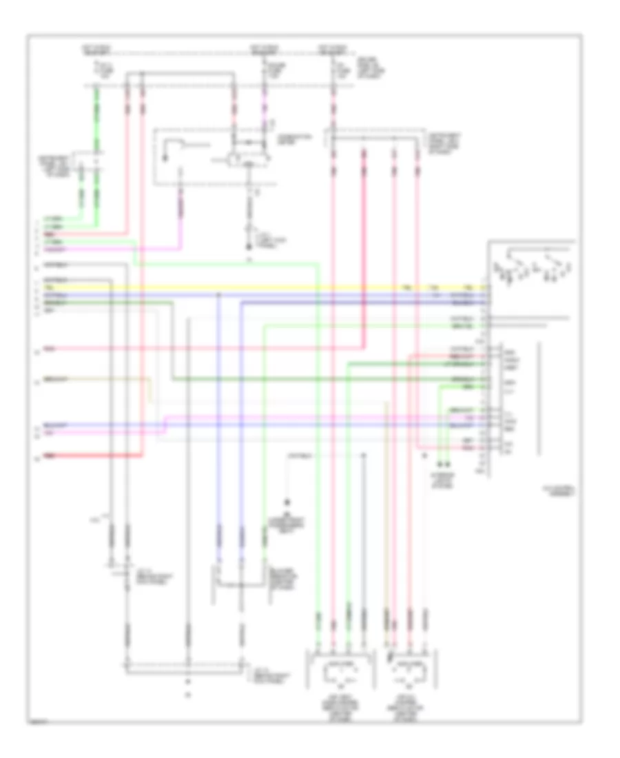
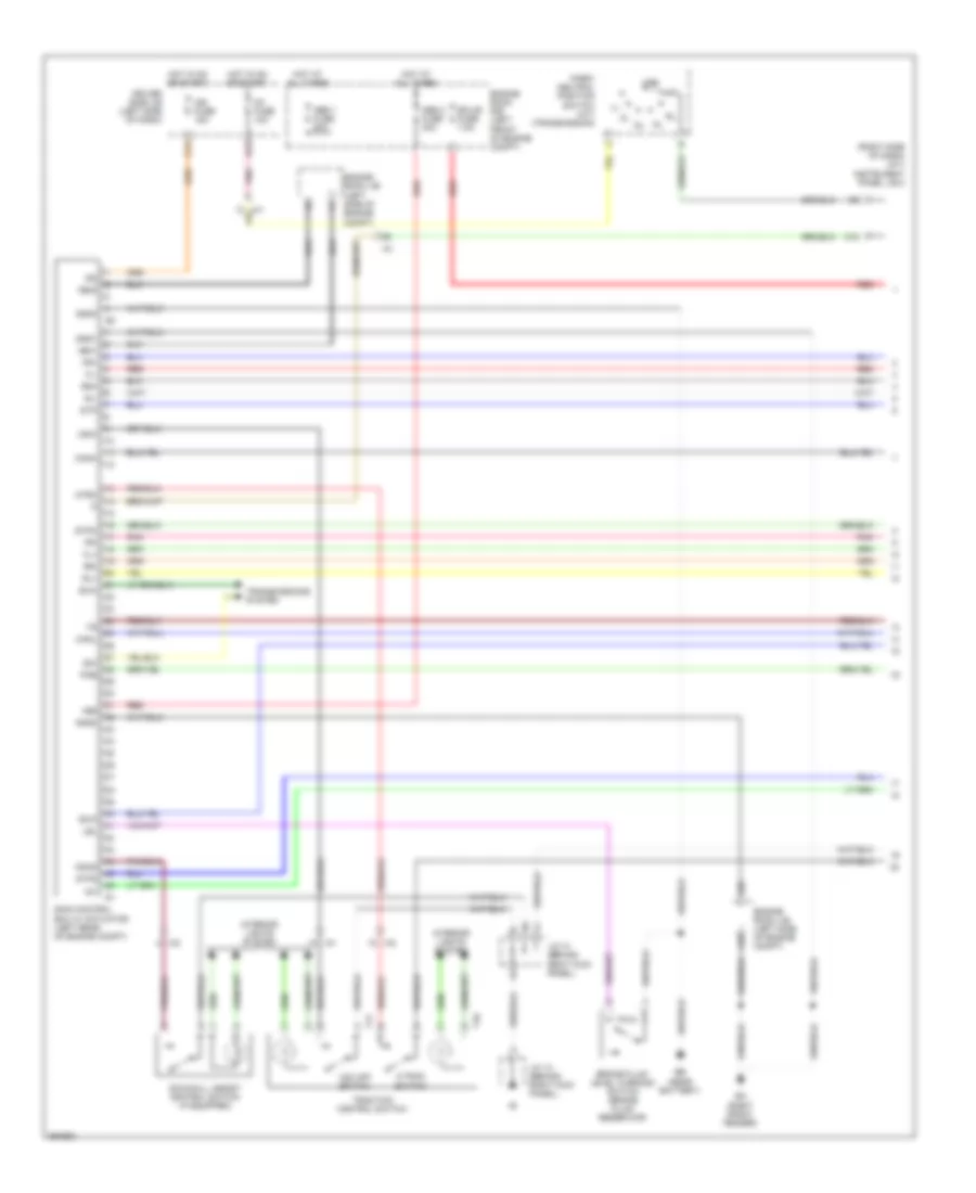
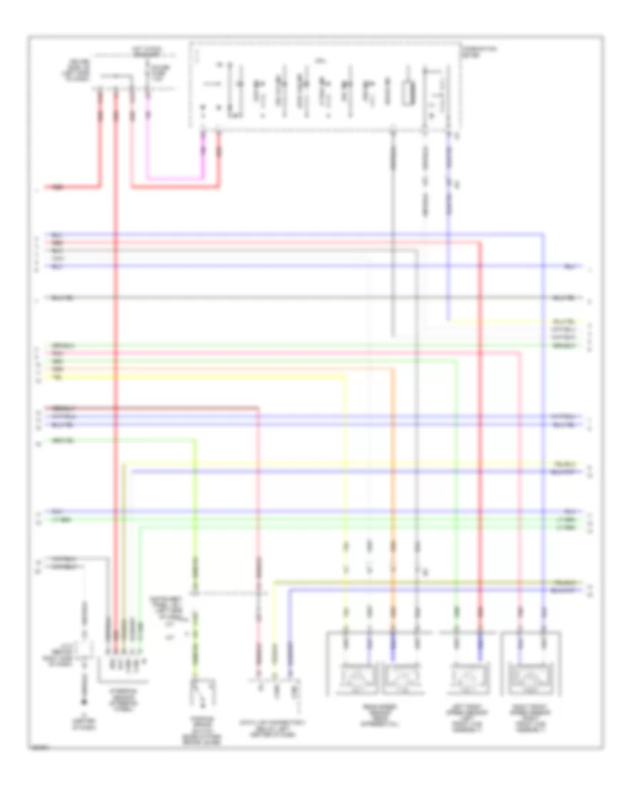
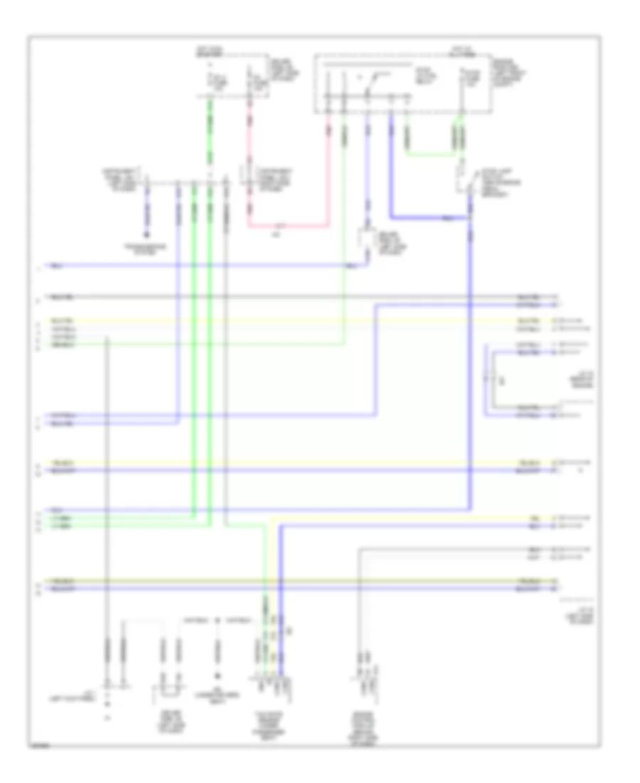
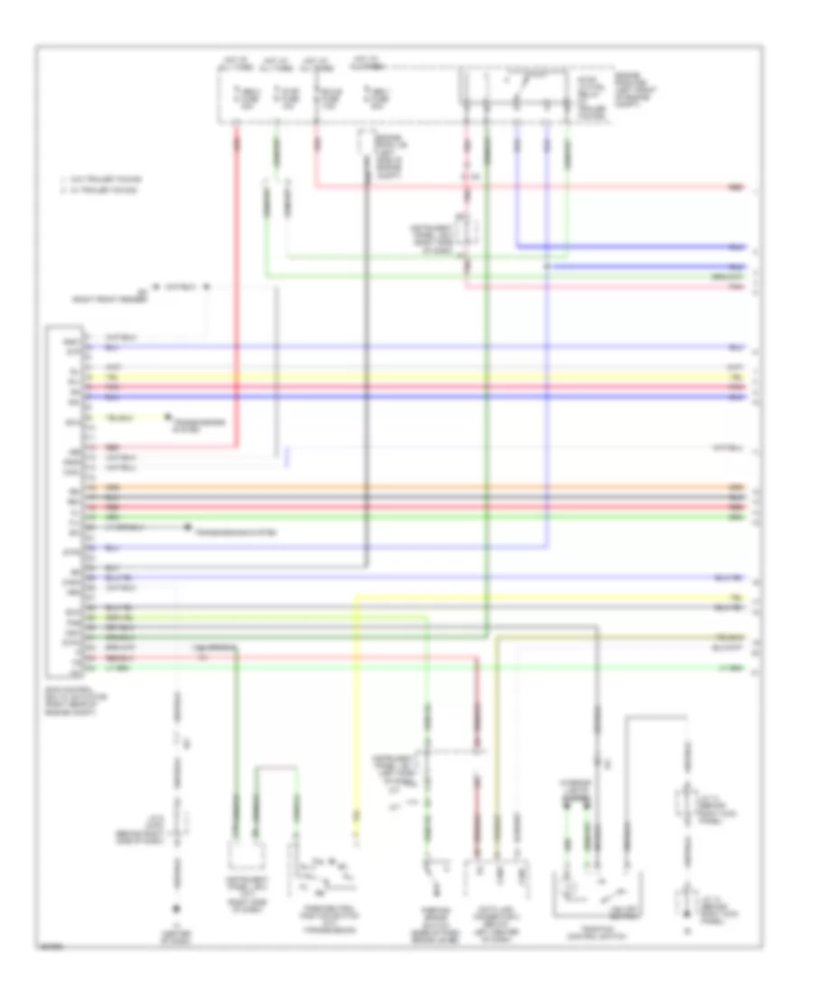
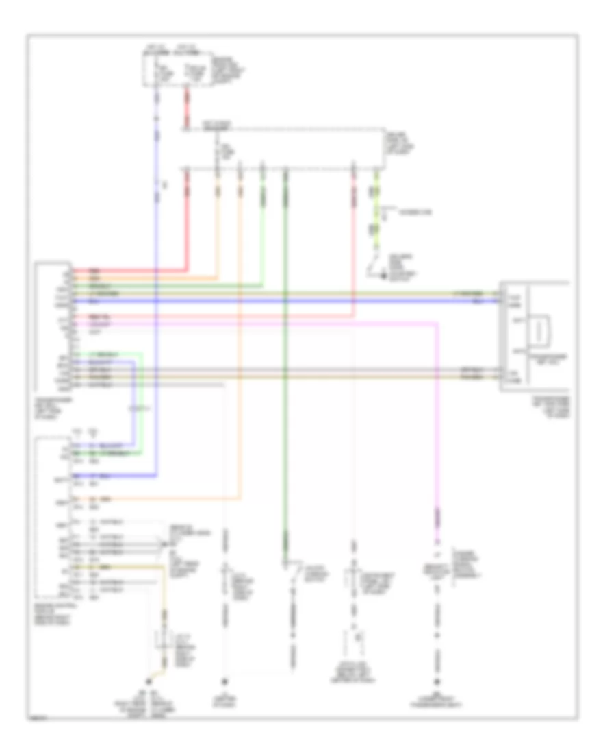
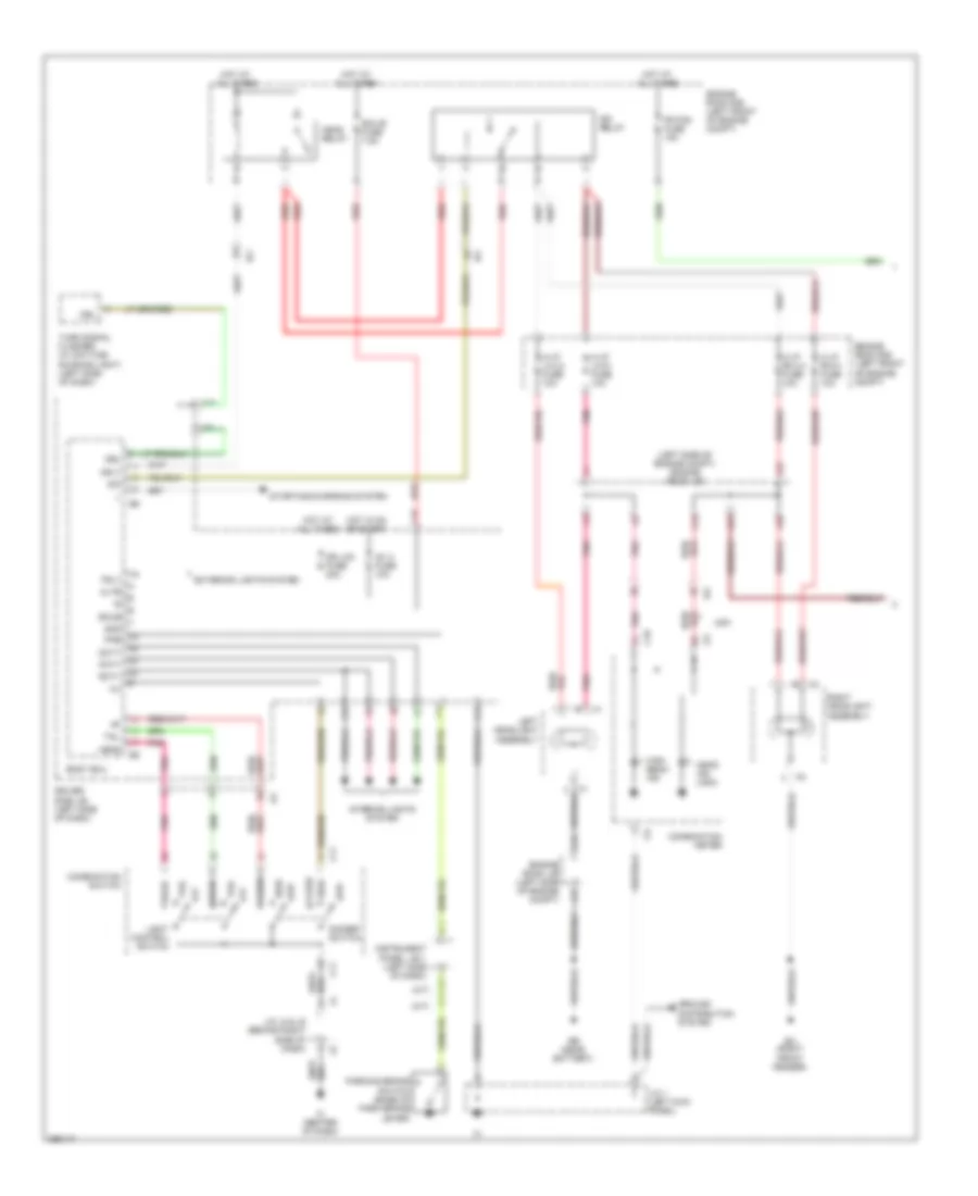
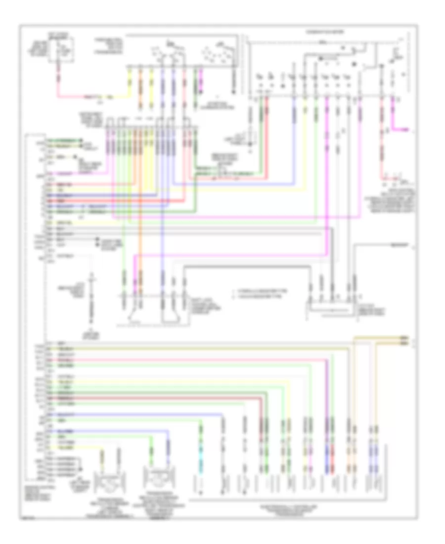
AIR CONDITIONING
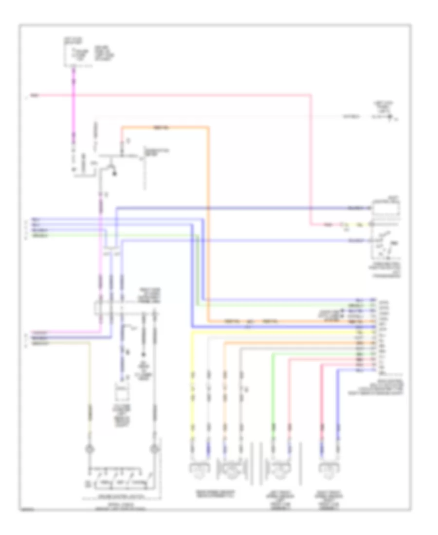
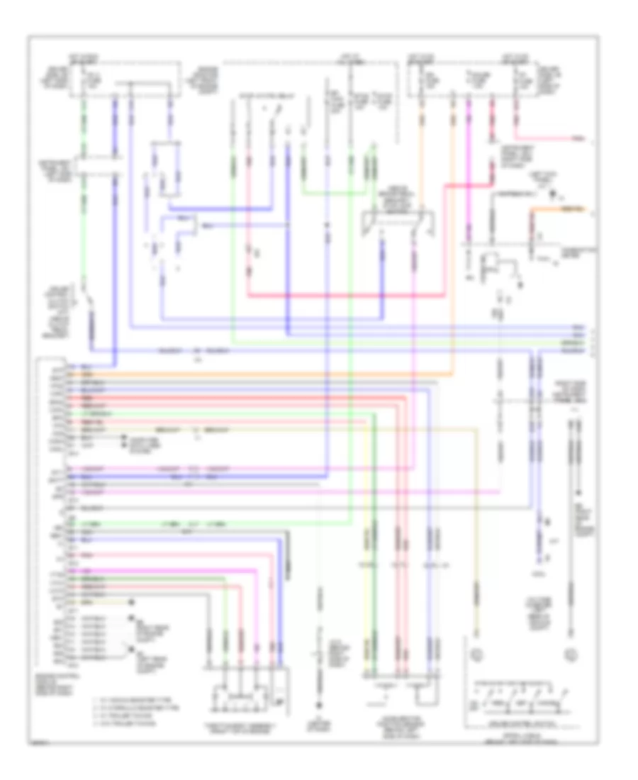
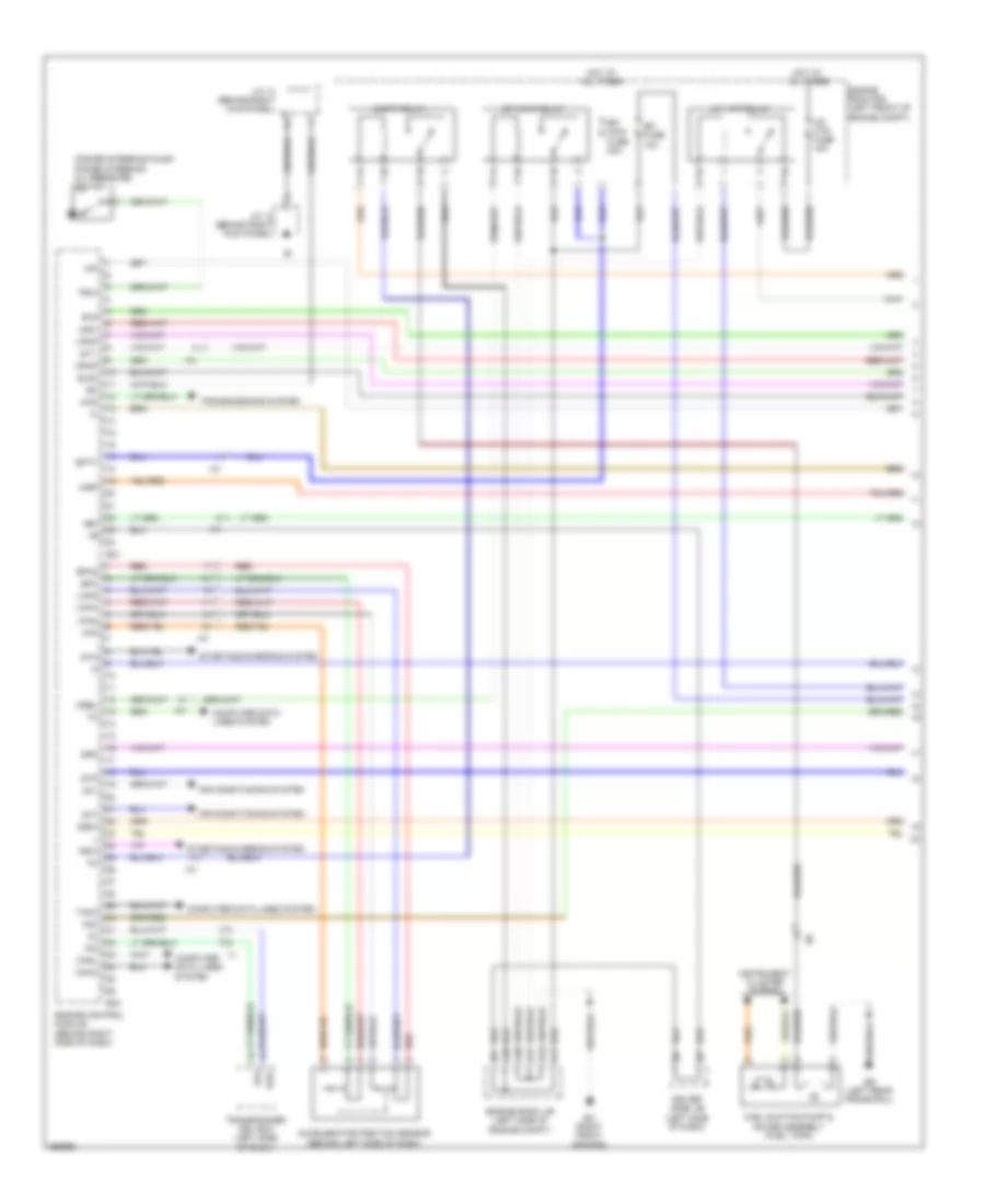
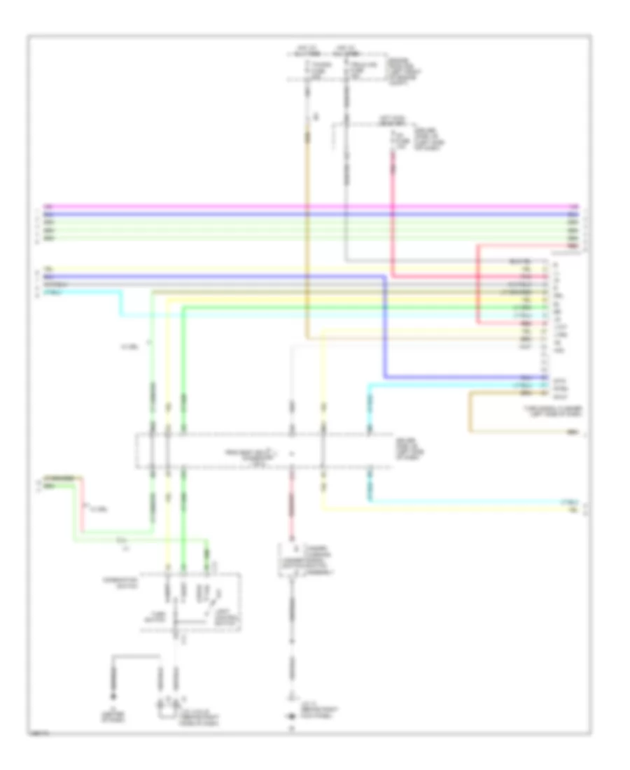
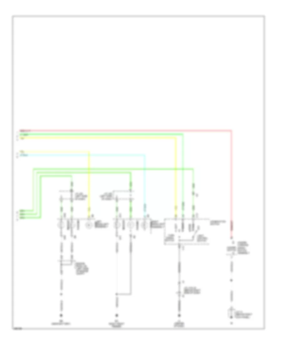
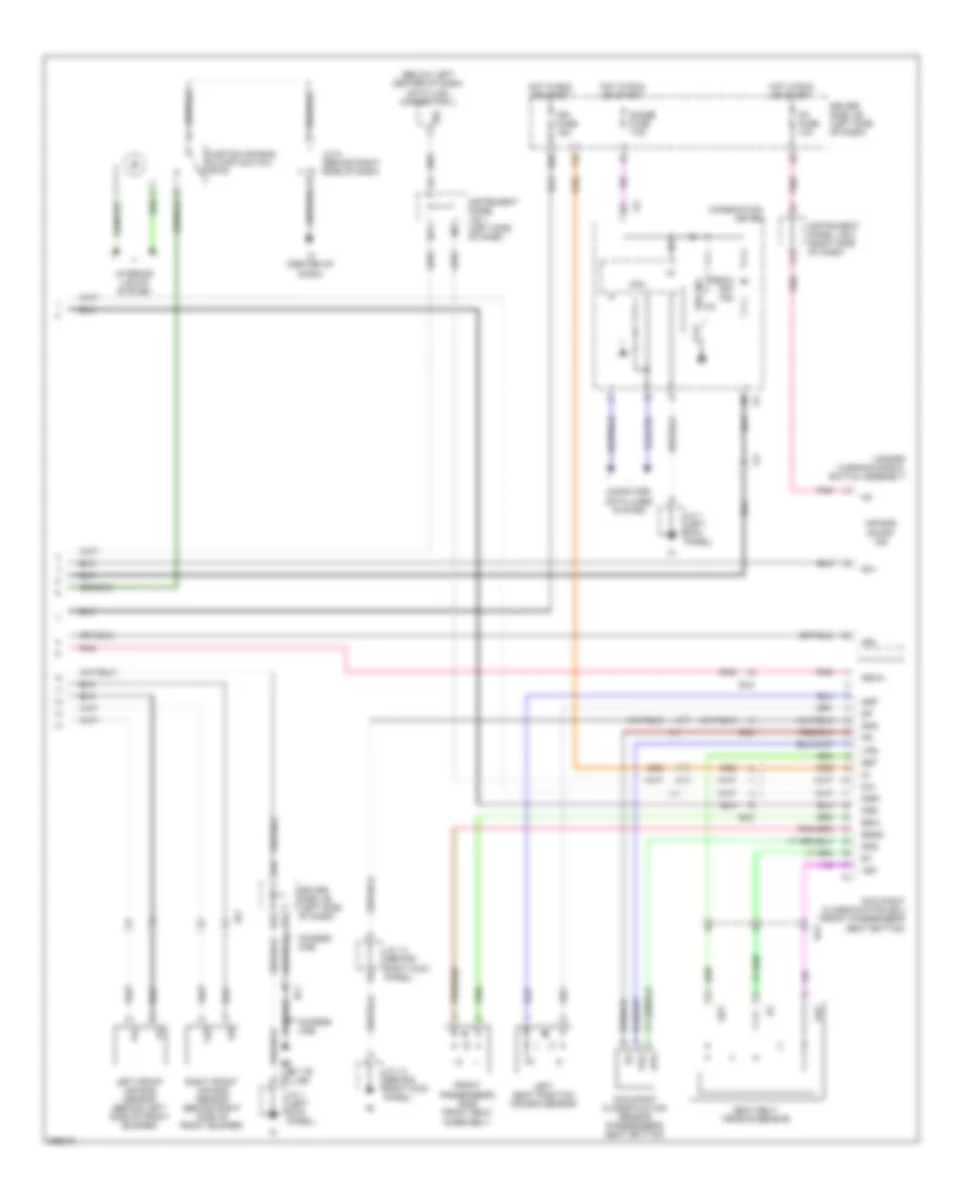
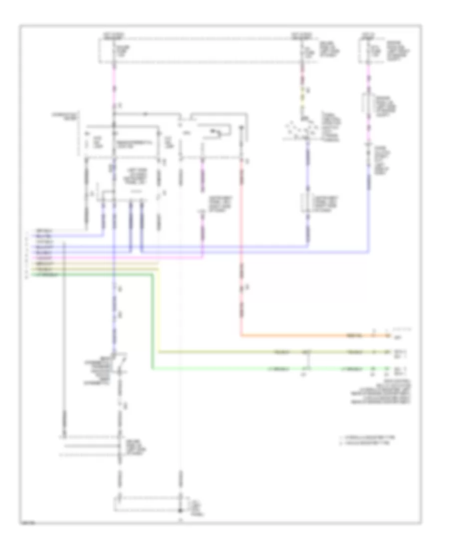
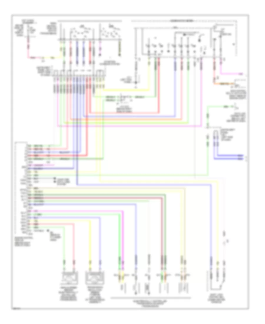
Manual A/C Wiring Diagram (1 of 2) for Toyota Tacoma X-Runner 2013
 https://portal-diagnostov.com/license.html
Automotive Electricians Portal FZCO
Automotive Electricians Portal FZCO
https://portal-diagnostov.com/license.html
https://portal-diagnostov.com/license.html
Automotive Electricians Portal FZCO
Automotive Electricians Portal FZCO
List of elements for Manual A/C Wiring Diagram (1 of 2) for Toyota Tacoma X-Runner 2013:
- (2.7l: rear of engine) (4.0l: top center of engine) engine coolant temperature sensor
- 2.7l
- 4.0l
- A/c
- A/c amplifier (right side of dash)
- A/c compressor (left front of engine)
- A/c fuse 10a
- A/c lock sensor
- A/c magnetic clutch
- A/c thermistor 1 (behind center of dash)
- A29
- A33
- Ac1
- Acid
- Act
- Air inlet damper servo motor (center of dash)
- Ambient temperature sensor (behind front grille, below hood release assembly)
- B10
- Blower motor (below right side of dash, in blower housing)
- Blrh
- Def
- E10
- E11
- E13
- E14
- E17
- E22
- Ea (right front fender)
- Ea1
- Ecu-b fuse 7.5a
- Engine control module (behind right side of dash)
- Engine controls system
- Engine room j/b (left side of engine compt)
- Engine room r/b (left front of engine compt)
- Ethw
- Except tmmtx made
- Frs
- Gnd
- Heater relay
- Hot at all times
- Htr fuse 50a
- Ia1
- Ia4
- Ig+
- Ign
- Ih1
- Ii1
- Ij1
- In1
- In2
- Inner rear view mirror
- Instrument panel j/b 2 (right side of dash)
- Ip2
- J/c 5 (behind right side of dash)
- Lock
- Mg clt relay
- Mgc
- Mr/f
- Pnk
- Pressure switch (behind right front headlight)
- Prs
- Rdef
- Rec
- Red
- Sg 2
- Solf
- Spd
- Tach
- Tam
- Tamo
- Temp
- Thw
- Thwo
- Tmmtx made
- Ver1
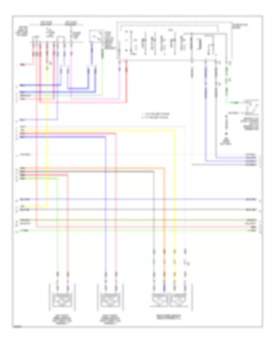
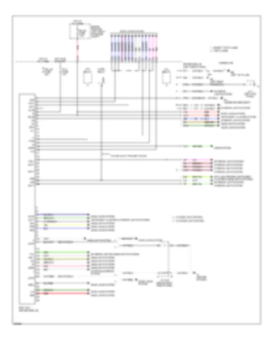
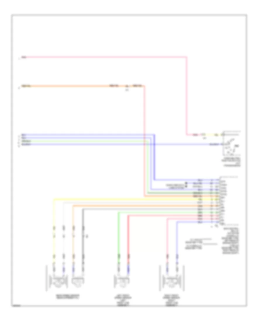
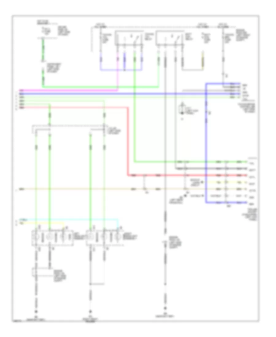
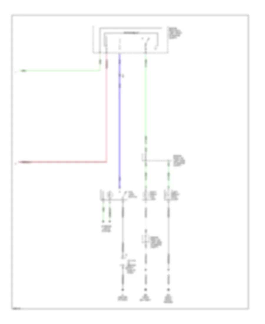
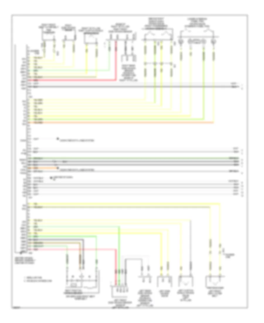
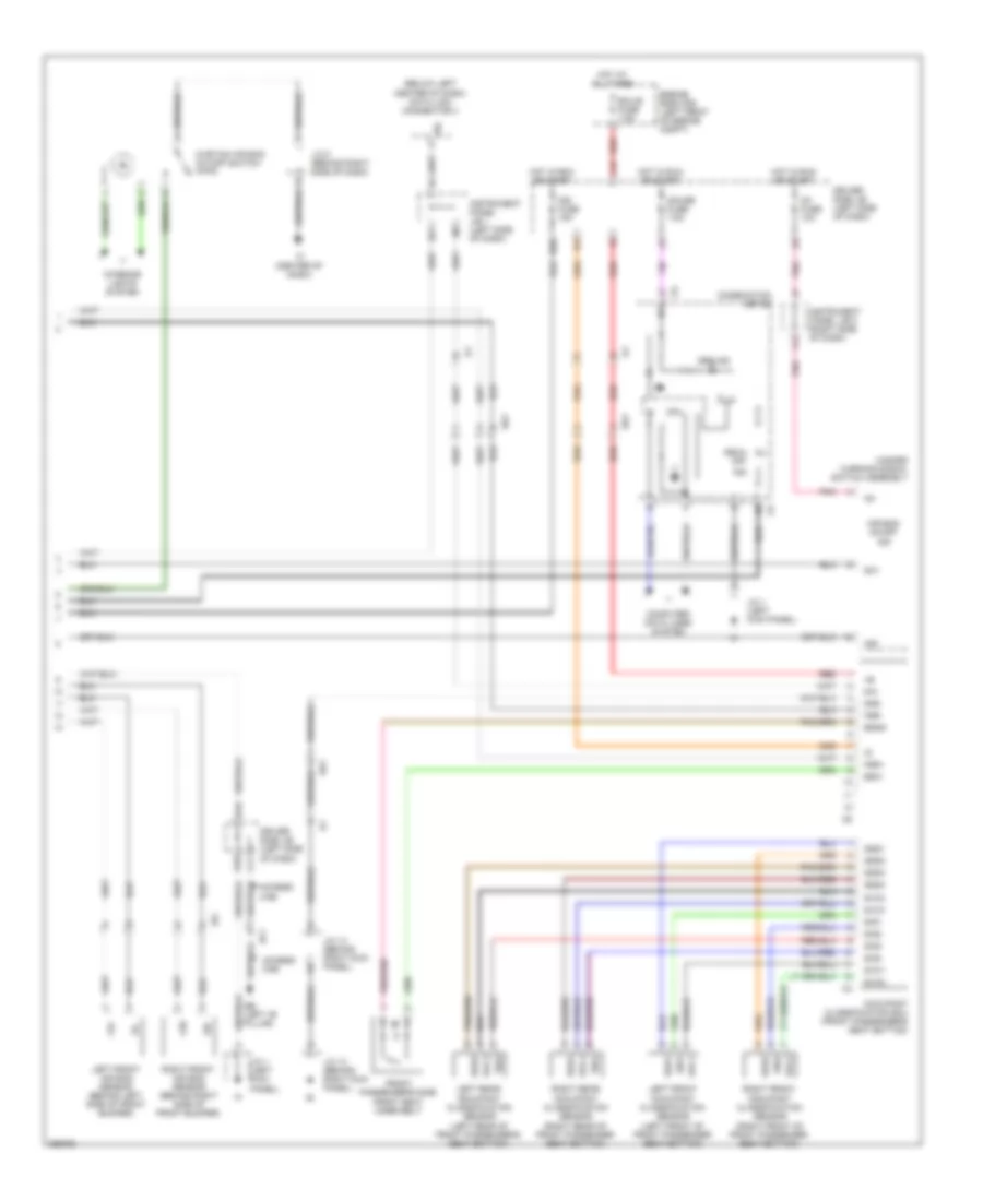
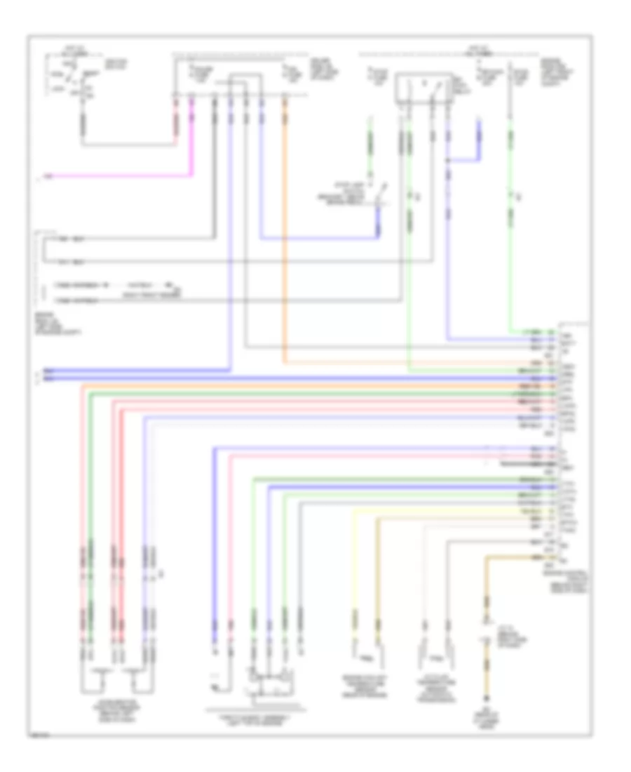
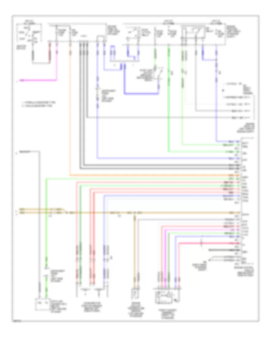
Manual A/C Wiring Diagram (2 of 2) for Toyota Tacoma X-Runner 2013
List of elements for Manual A/C Wiring Diagram (2 of 2) for Toyota Tacoma X-Runner 2013:
- 4.0l
- A/c
- A/c control assembly
- A15
- A33
- Acid
- Air mix damper servo motor (center of dash)
- Air vent mode damper servo motor (center of dash)
- Amplifier
- Amsw
- Bb (under front passenger's seat)
- Blower resistor (center of dash)
- C11
- C13
- C14
- C16
- Combination meter
- Cpu
- Driver side j/b (left side of dash)
- F14
- Gauge fuse 7.5a
- Gnd
- Hot in run or start
- Ia1
- Ig+
- Ig1 2 fuse 10a
- Ig1 fuse 10a
- Ill+
- Ill-
- Instrument panel j/b 1 (left side of dash)
- Instrument panel j/b 2 (right side of dash)
- Interior lights system
- J/c 1 (left kick panel)
- J/c 13 (behind right kick panel)
- J/c 14 (behind right kick panel)
- K13
- Max
- Mr/f
- Mset
- Off
- Pnk
- Rec
- Red
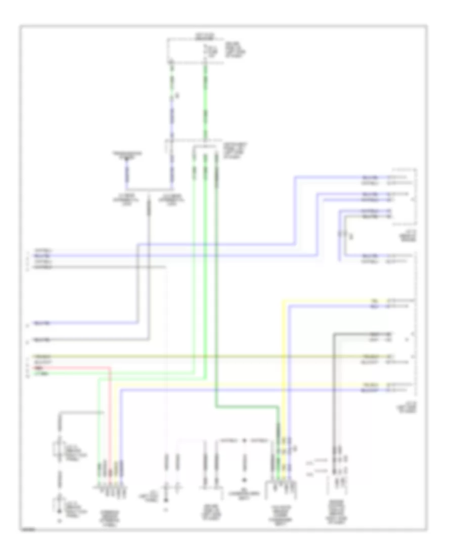
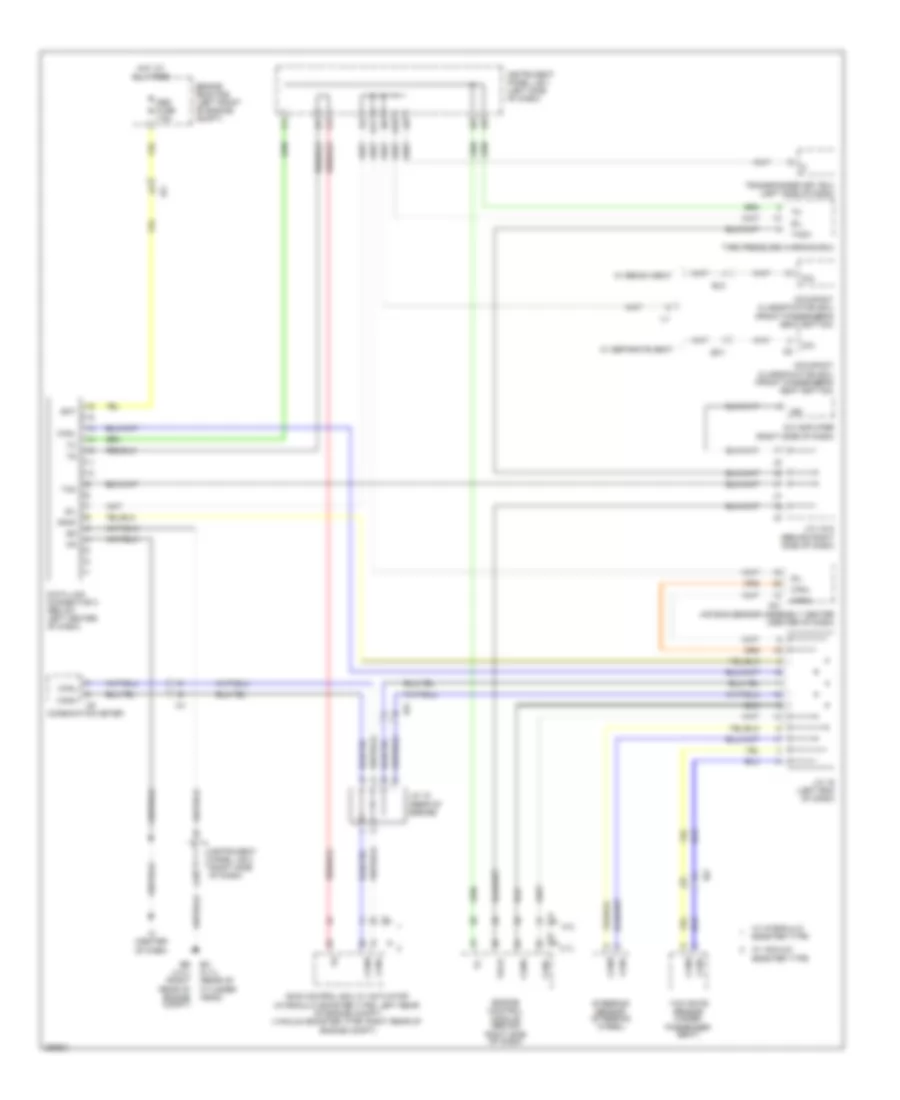
ANTI-LOCK BRAKES
Anti-lock Brakes Wiring Diagram, Hydraulic Booster Type (1 of 3) for Toyota Tacoma X-Runner 2013
List of elements for Anti-lock Brakes Wiring Diagram, Hydraulic Booster Type (1 of 3) for Toyota Tacoma X-Runner 2013:
- (right side of dash) (a/t) instrument panel j/b 2
- +bm1
- +bm2
- +bs
- A-trac switch
- A33
- A39
- Abs 1 fuse 50a
- Abs 2 fuse 30a
- Atrc
- Brake fluid level warning switch (brake fluid reservoir)
- C17
- C18
- Canh
- Canl
- Csw
- Downhill assist control switch (if equipped)
- Driver side j/b (left side of dash)
- Ea (right front fender)
- Eb (near battery)
- Ecu-b fuse 7.5a
- Engine room j/b (left side of engine compt)
- Engine room r/b (left front of engine compt)
- Exi
- Exi3
- Exi4
- Fl+
- Fl-
- Fr+
- Fr-
- Gnd1
- Gnd2
- Gnd3
- H13
- Hdcs
- Hot at all times
- Hot in on or start
- Ia1
- Ia3
- Ig1
- Ig1 fuse 10a
- Ig2
- Ign fuse 15a
- Interior lights system
- J/c 13 (behind right kick panel)
- J/c 14 (behind right kick panel)
- Lbl
- Park/ neutral position switch (a/t) (transmission)
- Pkb
- Pnk
- Red
- Rl+
- Rl-
- Rr+
- Rr-
- Skid control ecu w/ actuator (left rear of engine compt)
- Stp
- Stp2
- Stpo
- T17
- T18
- Traction control switch
- Transmissions system
- Vsc off switch
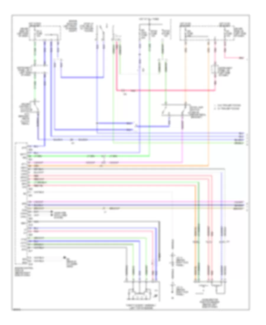
Anti-lock Brakes Wiring Diagram, Hydraulic Booster Type (2 of 3) for Toyota Tacoma X-Runner 2013
List of elements for Anti-lock Brakes Wiring Diagram, Hydraulic Booster Type (2 of 3) for Toyota Tacoma X-Runner 2013:
- A-trac ind
- A/t
- Abs ind
- Auto lsd ind
- Bat
- Brake ind
- Buzzer
- C15
- C16
- Canh
- Canl
- Combination meter
- Cpu
- Dac ind
- Data link connector 3 (below left center of dash)
- Driver side j/b (left side of dash)
- Ess
- Gauge fuse 7.5a
- Hot in run or start
- Ia1
- Ib1
- Ic (center of dash)
- Instrument panel j/b 1 (left side of dash)
- J/c 5 (behind right side of dash)
- K13
- Left front speed sensor (left front hub assembly)
- M/t
- Parking brake switch (base of park brake lever)
- Pnk
- Rear speed sensor (rear differential)
- Red
- Right front speed sensor (right front hub assembly)
- Slip ind
- Steering sensor (steering wheel)
- Vsc off ind
Anti-lock Brakes Wiring Diagram, Hydraulic Booster Type (3 of 3) for Toyota Tacoma X-Runner 2013
List of elements for Anti-lock Brakes Wiring Diagram, Hydraulic Booster Type (3 of 3) for Toyota Tacoma X-Runner 2013:
- A12
- A13
- Ba (under driver's seat)
- C13
- C14
- C15
- Canh
- Canl
- D12
- Driver side j/b (left side of dash)
- E14
- Engine control module (behind right side of dash)
- Engine room r/b (left front of engine compt)
- F10
- Gnd
- H18
- Hot at all times
- Hot in on or start
- Ia3
- Ie2
- Ig1 2 fuse 10a
- Ig1 fuse 10a
- Instrument panel j/b 1 (left side of dash)
- Instrument panel j/b 2 (right side of dash)
- J/c 1 (left kick panel)
- J/c 18 (rear of engine)
- J/c 19 (left side of dash)
- Pnk
- Stop fuse 10a
- Stop lamp switch (above brake pedal bracket)
- Stop lp ctrl relay
- Transmissions system
- Yaw rate sensor (under passenger seat)
Anti-lock Brakes Wiring Diagram, Vacuum Booster Type (1 of 3) for Toyota Tacoma X-Runner 2013
List of elements for Anti-lock Brakes Wiring Diagram, Vacuum Booster Type (1 of 3) for Toyota Tacoma X-Runner 2013:
- +bs
- A/t
- Abs 1 fuse 50a
- Abs 2 fuse 30a
- C15
- C18
- Canh
- Canl
- Csw
- Data link connector 3 (below left center of dash)
- Dl nl
- Ea (right front fender)
- Ecu-b fuse 7.5a
- Engine room j/b (left side of engine compt)
- Engine room r/b (left front of engine compt)
- Exi
- Exi3
- Exi4
- F7 pnk
- Fl+
- Fl-
- Fr+
- Fr-
- Gnd1
- Gnd2
- Hot at all times
- Ia1
- Ia3
- Ic (center of dash)
- Ig1
- Instrument panel j/b 1 (left side of dash)
- Instrument panel j/b 2 (a/t) (right side of dash)
- Instrument panel j/b 2 (right side of dash)
- Interior lights system
- J/c 13 (behind right kick panel)
- J/c 14 (behind right kick panel)
- J/c 5 (4wd) (behind right side of dash)
- M/t
- Neo
- Park/neutral position switch (a/t) (transmission)
- Parking brake switch (base of park brake lever)
- Pkb
- Pnk
- Red
- Rl+
- Rl-
- Rr+
- Rr-
- Skid control ecu w/ actuator (right rear of engine compt)
- Stop fuse 10a
- Stop lp ctrl relay (w/ trailer towing)
- Stp
- Stp2
- Stpo
- Traction control switch
- Transmissions system
- Vsc off switch
- W/ trailer towing
- W/o trailer towing
Anti-lock Brakes Wiring Diagram, Vacuum Booster Type (2 of 3) for Toyota Tacoma X-Runner 2013
List of elements for Anti-lock Brakes Wiring Diagram, Vacuum Booster Type (2 of 3) for Toyota Tacoma X-Runner 2013:
- Abs ind
- Auto lsd ind
- Brake fluid level warning switch (brake fluid reservoir)
- Brake ind
- Buzzer
- C10
- C15
- C16
- Combination meter
- Cpu
- Driver side j/b (left side of dash)
- Eb (near battery)
- Gauge fuse 7.5a
- H13
- Hot in on or start
- Ia1
- Ib1
- Ig1 fuse 10a
- Ih1
- K13
- Left front speed sensor (left front hub assembly)
- Pnk
- Rear speed sensor (rear differential)
- Red
- Right front speed sensor (right front hub assembly)
- Slip ind
- Stop lamp switch (above brake pedal bracket)
- Trac off ind
- Vsc off ind
- W/ trailer towing
- W/o trailer towing
Anti-lock Brakes Wiring Diagram, Vacuum Booster Type (3 of 3) for Toyota Tacoma X-Runner 2013
List of elements for Anti-lock Brakes Wiring Diagram, Vacuum Booster Type (3 of 3) for Toyota Tacoma X-Runner 2013:
- 2.7l
- 4.0l
- A12
- A13
- Ba (under driver's seat)
- Bat
- C13
- C14
- Canh
- Canl
- D12
- Driver side j/b (left side of dash)
- E14
- E22
- Engine control module (behind right side of dash)
- Ess
- F10
- Gnd
- H18
- Hot in on or start
- Ia3
- Ib1
- Ie2
- Ig1 2 fuse 10a
- Instrument panel j/b 1 (left side of dash)
- J/c 1 (left kick panel)
- J/c 13 (behind right kick panel)
- J/c 14 (behind right kick panel)
- J/c 18 (rear of engine)
- J/c 19 (left side of dash)
- Red
- Steering sensor (steering wheel)
- Transmissions system
- W/ rear differential lock
- W/o rear differential lock
- Yaw rate sensor (under passenger seat)
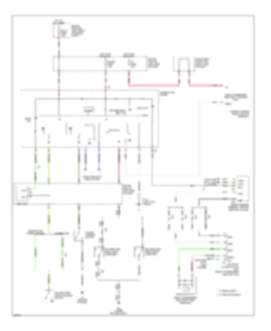
ANTI-THEFT
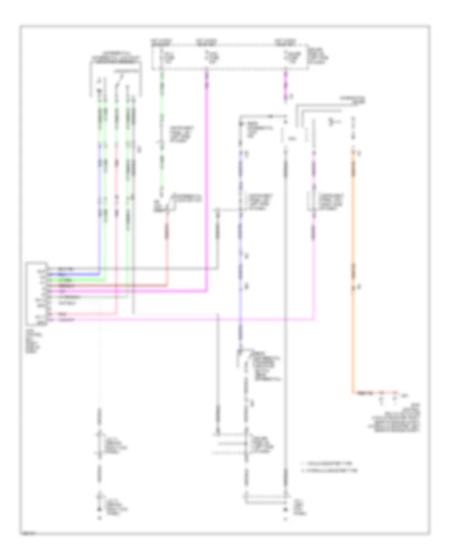
Forced Entry Wiring Diagram for Toyota Tacoma X-Runner 2013
List of elements for Forced Entry Wiring Diagram for Toyota Tacoma X-Runner 2013:
- Access cab
- Altb
- Be (left "b" pillar)
- Bf (right "c" pillar)
- Bf1
- Bg1
- Body ecu
- C10
- C16
- Dcty
- Door control receiver (right side of dash)
- Double cab
- Dr lck fuse 20a
- Driver side j/b (left side of dash)
- Driver's side door courtesy switch
- Driver's side door lock assembly
- Ecu-b fuse 7.5a
- Ecub
- Engine room r/b (left front of engine compt)
- Front passenger's side door courtesy switch
- Front passenger's side door lock assembly
- Gnd
- H18
- Haz
- Horn
- Horn relay
- Hot at all times
- Hot in run or start
- I16
- Ic (center of dash)
- Ic6
- Ig1 2 fuse 10a
- Ik3
- Il1
- J/c 1 (left kick panel)
- J/c 13 (behind right kick panel)
- J/c 14 (behind right kick panel)
- J/c 4 & 5 (behind right side of dash)
- J15
- K10
- Ksw
- Left rear door courtesy switch
- Left rear lower side door courtesy switch
- Left rear upper side door courtesy switch
- Lswd
- Lswp
- Pcty
- Prg
- Rcty
- Rda
- Red
- Right rear door courtesy switch
- Right rear lower side door courtesy switch
- Right rear upper side door courtesy switch
- Turn signal flasher (w/ trailer towing) (left side of dash)
- Unlock warning switch
- W/ door lock control
- W/o door lock control
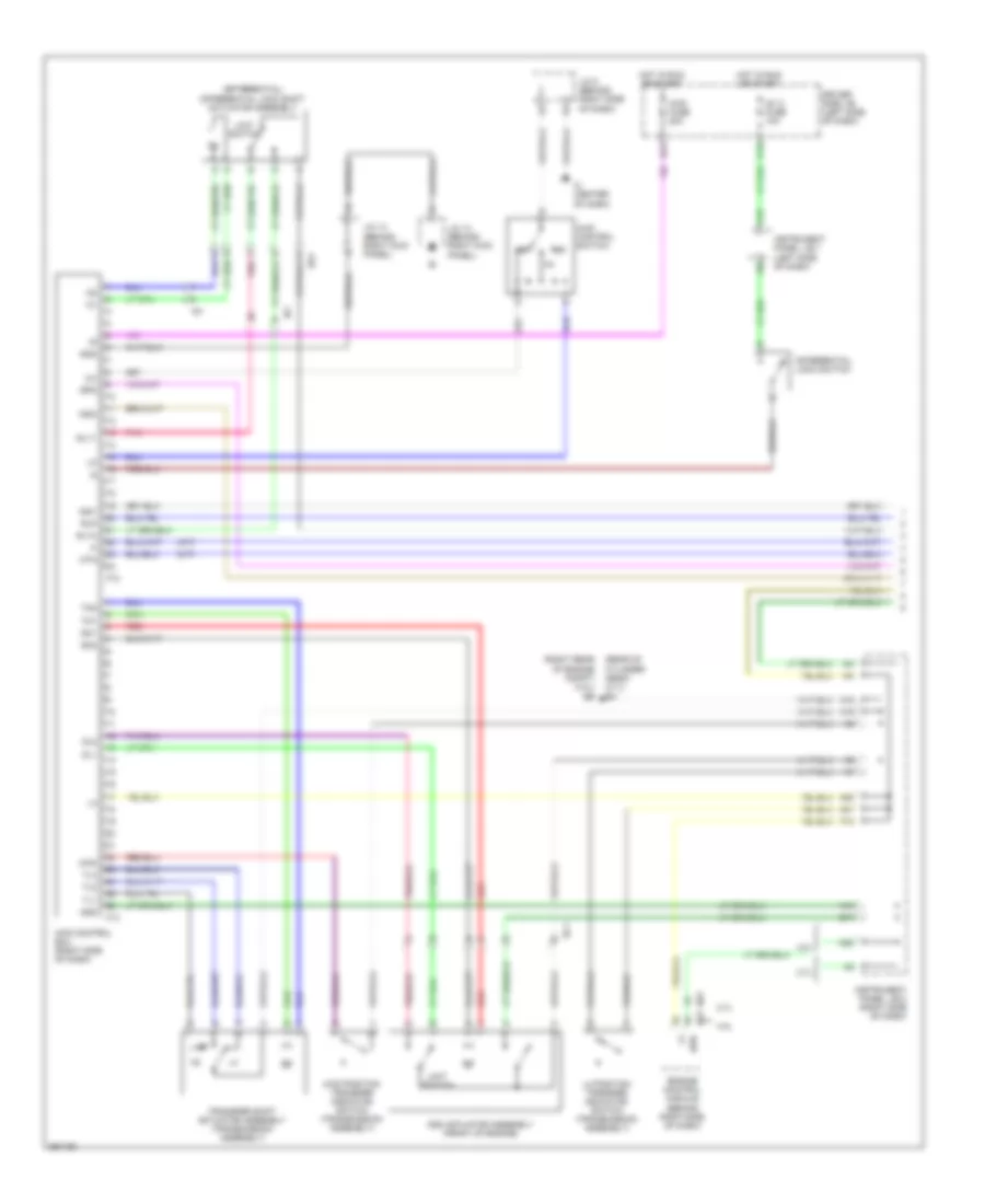
Immobilizer Wiring Diagram for Toyota Tacoma X-Runner 2013
List of elements for Immobilizer Wiring Diagram for Toyota Tacoma X-Runner 2013:
- (4.0l) (right rear of engine compt)
- (rear of cylinder head) (2.7l) eg
- 2.7l
- 4.0l
- Access cab
- Agnd
- Ant1
- Ant2
- Batt
- Bb (under front passenger's seat)
- Bf1
- C16
- Code
- Cty
- Data link connector 3 (below left center of dash)
- Driver side j/b (left side of dash)
- Driver's side door courtesy switch
- E01
- E02
- E03
- E04
- E05
- E11
- E12
- E13
- E14
- E19
- E20
- E21
- E22
- Ecu-b fuse 7.5a
- Ee eh (2.7l) (rear of cylinder head)
- Ef (4.0l) (left rear of engine compt)
- Efi fuse 20a
- Efii
- Efio
- Engine control module (behind right side of dash)
- Engine room r/b (left front of engine compt)
- Gnd
- Hazard warning signal switch assembly
- Hot at all times
- Hot in run or start
- I15
- Ia1
- Ic (center of dash)
- Ign fuse 15a
- Igsw
- Il1
- Imi
- Imo
- Ind
- Instrument panel j/b 1 (left side of dash)
- J/c 12 (2.7l) (behind right side of dash)
- J/c 5 (behind right side of dash)
- J14
- K10
- Ksw
- Me01
- Red
- Security indicator light
- Sil
- Transponder key amplifier (left side of dash)
- Transponder key coil
- Transponder key ecu (left side of dash)
- Txct
- Unlock warning switch
- Vc5
BODY CONTROL MODULES
Body Control Modules Wiring Diagram for Toyota Tacoma X-Runner 2013
List of elements for Body Control Modules Wiring Diagram for Toyota Tacoma X-Runner 2013:
- Access cab
- Act+
- Act-
- Actd
- Acty
- Altb
- Anti-lock brakes, instrument cluster & headlights systems
- Ba (under driver's seat)
- Bd (left rear frame rail)
- Be (left "b" pillar)
- Bf1
- Body ecu (driver side j/b)
- Bzr
- C10
- C16
- Dbkl
- Dcty
- Dim
- Door locks system
- Dr lck fuse 20a
- Driver side j/b (left side of dash)
- Drl
- E11
- E12
- Ecu-b fuse 7.5a
- Ecub
- Ehw
- Engine room r/b (left front of engine compt)
- Except tmmtx made
- Exterior lights & headlights systems
- Exterior lights system
- F10
- F11
- Flash relay
- Gnd
- H18
- H22
- H23
- H24
- Haz
- Head
- Headlights system
- Horn
- Horns system
- Hot at all times
- Hot in on or start
- Hrly
- I14
- I16
- I17
- I18
- I19
- Ic (center of dash)
- Ig1 2 fuse 10a
- Ile
- Instrument cluster & interior lights systems
- Instrument cluster system
- Interior lights system
- J/c 1 (left kick panel)
- J/c 4 & 5 (behind right side of dash)
- J15
- K10
- K13
- Ksw
- Lswd
- Lswp
- O11
- O12
- P/w relay
- Pcty
- Pkb
- Pnk
- Prg
- Pws
- Rcty
- Rda
- Red
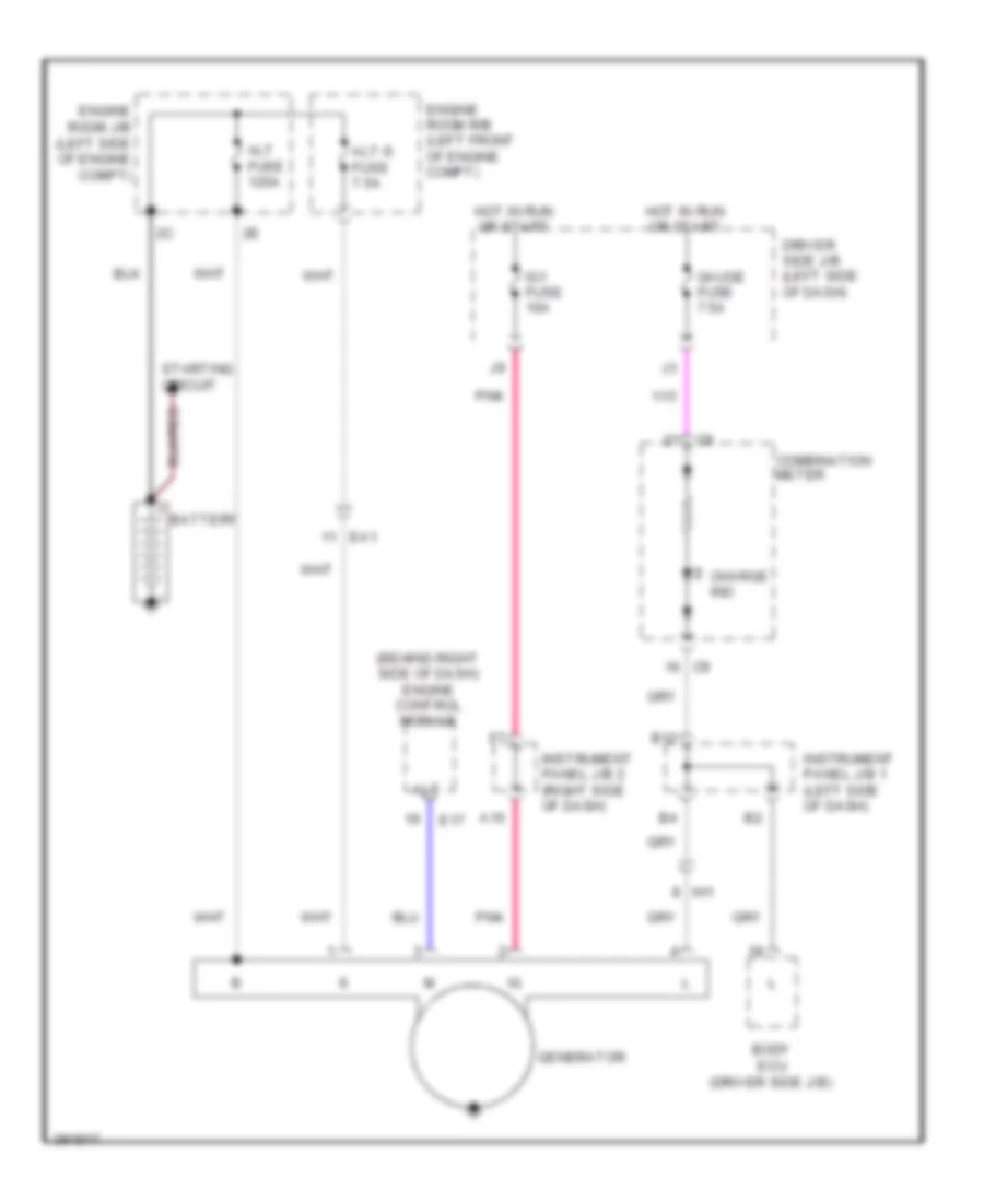
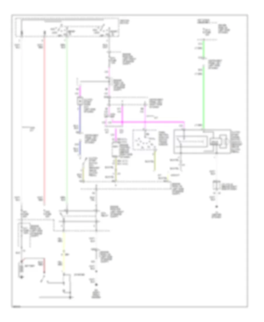
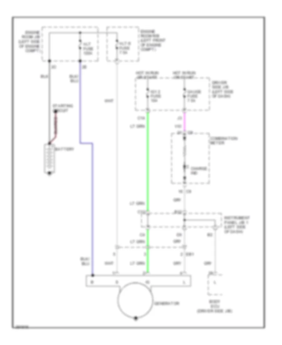
- Starting/charging system
- Tail
- Tail relay
- Tmmtx made
- Trly
- Ul1
- Ul2
- Ul3
- W/ door lock control
- W/o door lock control
- W/o drl & w/o trailer towing
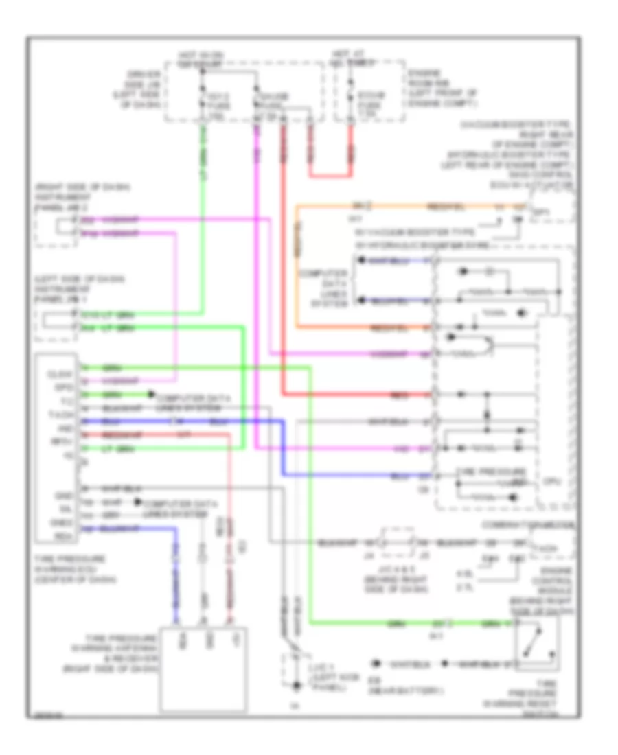
COMPUTER DATA LINES
Computer Data Lines Wiring Diagram for Toyota Tacoma X-Runner 2013
List of elements for Computer Data Lines Wiring Diagram for Toyota Tacoma X-Runner 2013:
- 2.7l
- 4.0l
- A/c amplifier (right side of dash)
- A18
- A21
- Air bag sensor assembly center (center of dash)
- B17
- B18
- Bat
- Bh1
- Bj2
- Canh
- Canl
- Combination meter
- Data link connector 3 (below left center of dash)
- Dia
- E14
- E22
- Ee (4.0l) (right rear of engine compt)
- Eh (2.7l) (rear of cylinder head)
- Engine control module (behind right side of dash)
- Engine room r/b (left front of engine compt)
- Hot at all times
- Ia1
- Ia3
- Ic (center of dash)
- Ie2
- Ign
- Il1
- Instrument panel j/b 1 (left side of dash)
- Instrument panel j/b 2 (right side of dash)
- J/c 18 (rear of engine)
- J/c 19 (left end of dash)
- J/c 4 & 5 (behind right side of dash)
- Obd fuse 7.5a
- Occupant classification ecu (front passenger's seat bottom)
- Sil
- Skid control ecu w/ actuator (hydraulic booster type: left rear of engine compt) (vacuum booster type: right rear of engine compt)
- Steering sensor (steering wheel)
- Tac
- Tach
- Tire pressure warning ecu
- Transponder key ecu (left side of dash)
- W/ bench seat
- W/ hydraulic booster type
- W/ separate seat
- W/ vacuum booster type
- Yaw rate sensor (under passenger seat)
CRUISE CONTROL
2.7L
2.7L, Cruise Control Wiring Diagram (1 of 2) for Toyota Tacoma X-Runner 2013
List of elements for 2.7L, Cruise Control Wiring Diagram (1 of 2) for Toyota Tacoma X-Runner 2013:
- +bm
- Accelerator position sensor (behind left side of dash)
- Batt
- C13
- C14
- C15
- Canh
- Canl
- Ccs
- Computer data lines system
- Cruise control clutch switch (m/t) (bracket above clutch pedal)
- Driver side j/b (left side of dash)
- E03
- E04
- E17
- E19
- E20
- E21
- E22
- Efi main fuse 20a
- Eg (rear of cylinder head)
- Engine control module (behind right side of dash)
- Engine room r/b (left front of engine compt)
- Epa
- Epa2
- Eta
- Etcs fuse 10a
- Ge01
- H13
- Hot at all times
- Hot in on or start
- Hot in run or start
- I15
- Ia1
- Ia3
- Ig1 2 fuse 10a
- Ig1 fuse 10a
- Ign fuse 15a
- Igsw
- Ii1
- Instrument panel j/b (left side of dash)
- Instrument panel j/b 1 (left side of dash)
- J/c 13 (behind right kick panel)
- J/c 14 (behind right kick panel)
- Nca
- Pnk
- Red
- Spd
- St1-
- Stop fuse 10a
- Stop lamp switch (above brake pedal bracket)
- Stop lp ctrl relay (w/ trailer towing)
- Stp
- Throttle body assembly (left top of engine)
- Vcp2
- Vcpa
- Vcta
- Vpa
- Vpa2
- Vta1
- Vta2
- W/ trailer towing
- W/o trailer towing
2.7L, Cruise Control Wiring Diagram (2 of 2) for Toyota Tacoma X-Runner 2013
List of elements for 2.7L, Cruise Control Wiring Diagram (2 of 2) for Toyota Tacoma X-Runner 2013:
- (left kick panel)
- (right side of dash) instrument panel j/b 2
- +res
- -set
- A/t
- A18
- C12
- C16
- Cancel
- Canh
- Canl
- Cccl
- Combination meter
- Computer data lines system
- Cpu
- Cruise control switch
- Cruise ind
- Driver side j/b (left side of dash)
- E15
- Eh (rear of cylinder head)
- Fl+
- Fl-
- Fr+
- Fr-
- Gauge fuse 7.5a
- Hot in on or start
- Ia1
- Ib1
- Ih1
- Im1
- J/c 1
- Left front speed sensor (left front hub assembly)
- M/t
- On- off
- Park/neutral position switch (a/t) (transmission)
- Pnk
- Rear speed sensor (rear differential)
- Red
- Right front speed sensor (right front hub assembly)
- Rl+
- Rl-
- Rr+
- Rr-
- Shift control ecu
- Skid control ecu w/ actuator (vacuum booster type: right rear of engine compt)
- Sp1
- Spiral cable (behind left side of dash)
- Stp
- Stp2
- Stpo
- Voltage inverter (left rear of vehicle compt)
4.0L
4.0L, Cruise Control Wiring Diagram (1 of 2) for Toyota Tacoma X-Runner 2013
List of elements for 4.0L, Cruise Control Wiring Diagram (1 of 2) for Toyota Tacoma X-Runner 2013:
- (above brake pedal bracket) stop lamp switch
- (left kick panel) j/c 1
- (right side of dash) instrument panel j/b 2
- +bm
- +res
- -set
- A18
- Accelerator position sensor (behind left side of dash)
- B12
- Batt
- C12
- C13
- C14
- C15
- Cancel
- Canh
- Canl
- Cccl
- Ccs
- Combination meter
- Compt)
- Computer data lines system
- Cpu
- Cruise control clutch switch (m/t) (above clutch pedal bracket)
- Cruise control switch
- Cruise ind
- Driver side j/b (left side of dash)
- E01
- E02
- E03
- E04
- E05
- E11
- E12
- E13
- E14
- E15
- Ea1
- Ee (right rear of engine
- Ee (right rear of engine compt)
- Ef (left rear of engine compt)
- Efi main fuse 20a
- Engine control module (behind right side of dash)
- Engine room r/b (left front of engine compt)
- Epa
- Epa2
- Eta
- Etcs fuse 10a
- Gauge fuse 7.5a
- Ge01
- H13
- Hot at all times
- Hot in on or start
- Hot in run or start
- I15
- Ia1
- Ia3
- Ic (center of dash)
- Ig1 2 fuse 10a
- Ig1 fuse 10a
- Ign fuse 15a
- Igsw
- Ii1
- Im1
- Instrument panel j/b 1 (left side of dash)
- Instrument panel j/b 2 (right side of dash)
- J/c 5 (behind right side of dash)
- M/t
- Me01
- Nca
- On- off
- Pnk
- Red
- Spd
- Spiral cable (behind left side of dash)
- St1-
- Stop fuse 10a
- Stop lp ctrl relay
- Stp
- Throttle body assembly (front top of engine)
- Vcp2
- Vcpa
- Vcta
- Voltage inverter (left rear of vehicle compt)
- Vpa
- Vpa2
- Vta1
- Vta2
- W/ hydraulic booster type
- W/ trailer towing
- W/ vaccum booster type
- W/o trailer towing
4.0L, Cruise Control Wiring Diagram (2 of 2) for Toyota Tacoma X-Runner 2013
List of elements for 4.0L, Cruise Control Wiring Diagram (2 of 2) for Toyota Tacoma X-Runner 2013:
- Booster type
- Canh
- Canl
- Computer data lines system
- Fl+
- Fl-
- Fr+
- Fr-
- Ia1
- Ib1
- Ih1
- Left front speed sensor (left front hub assembly)
- Park/neutral position switch (a/t) (transmission)
- Pnk
- Rear speed sensor (rear differential)
- Red
- Right front speed sensor (right front hub assembly)
- Rl+
- Rl-
- Rr+
- Rr-
- Skid control ecu w/ actuator (hydraulic booster type: left rear of engine compt) (vacuum booster type: right rear of engine compt)
- Sp1
- Stp
- Stp2
- Stpo
- W/ hydraulic booster type
- W/ vacuum
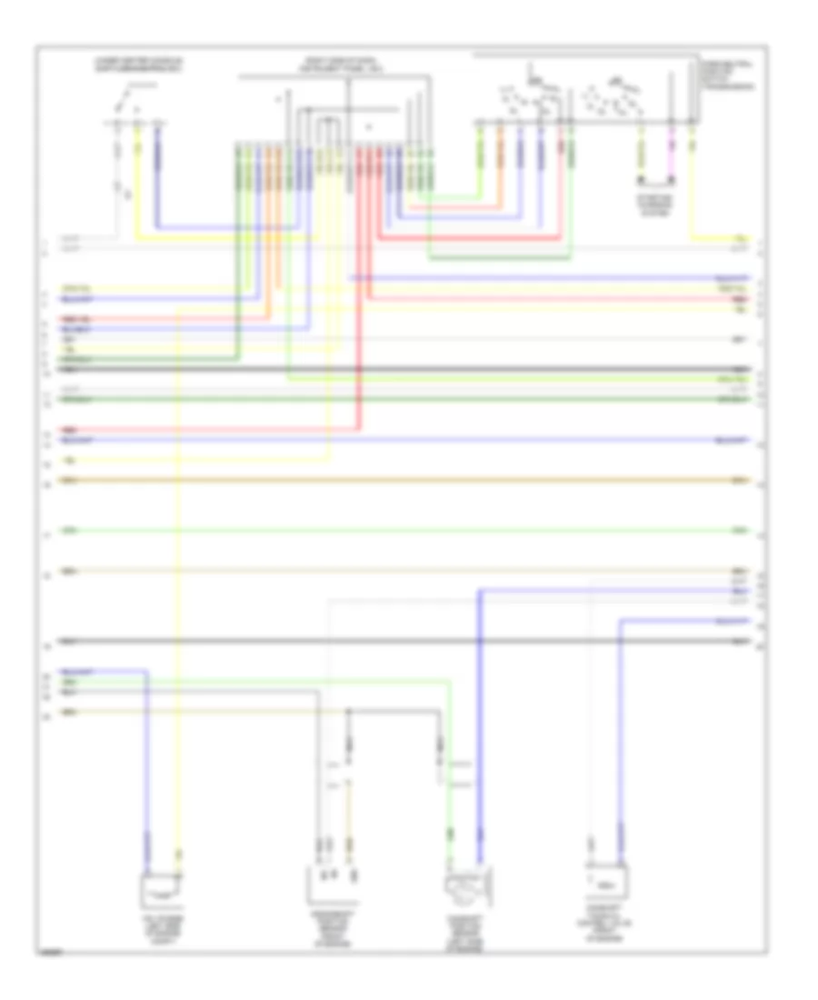
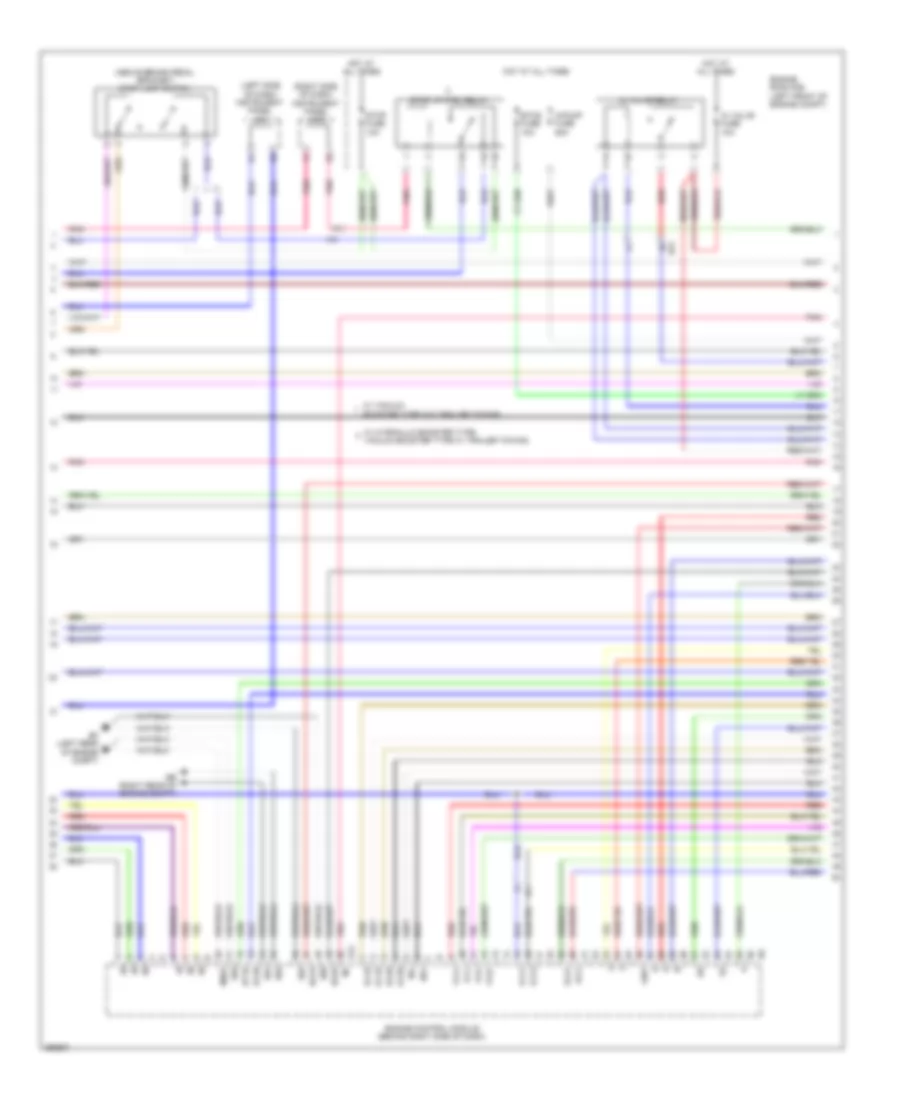
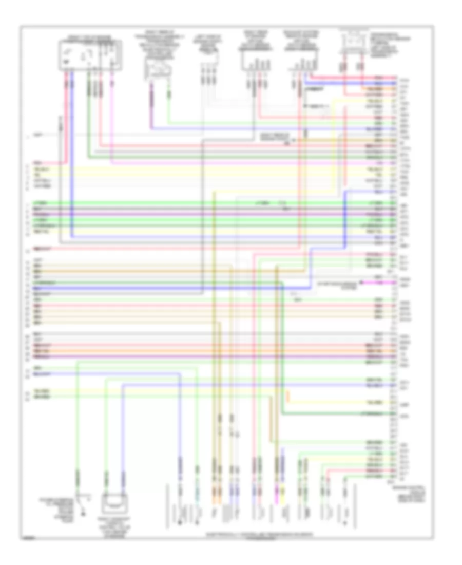
ENGINE PERFORMANCE
2.7L
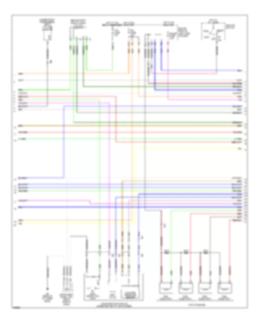
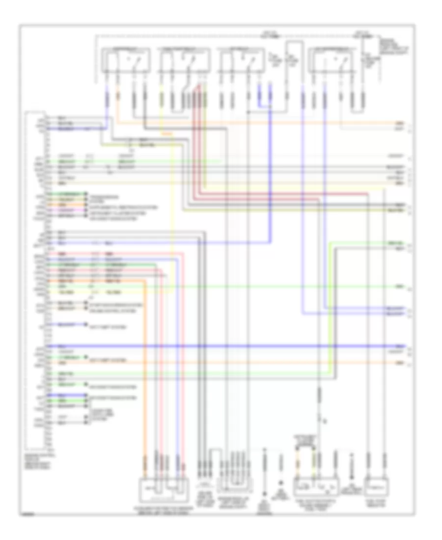
2.7L, Engine Performance Wiring Diagram (1 of 7) for Toyota Tacoma X-Runner 2013
List of elements for 2.7L, Engine Performance Wiring Diagram (1 of 7) for Toyota Tacoma X-Runner 2013:
- (behind left side of dash)
- (power steering pump) power steering oil pressure switch
- +bm
- 4wd
- A/f htr fuse 15a
- A/f htr relay
- A10
- A11
- A30
- A31
- A33
- Ac1
- Accelerator position sensor
- Act
- Aidi
- Aip
- Air conditioning system
- Airp
- Airv
- Batt
- Bd (left rear frame rail)
- C/opn relay
- Canh
- Canl
- Computer data lines system
- Driver side j/b (left side of dash)
- E21
- E22
- Ea (right front fender)
- Efi fuse 10a
- Efi main fuse 20a
- Efi main relay
- Efii
- Efio
- Els
- Els3
- Engine control module (behind right side of dash)
- Engine room j/b (left side of engine compt)
- Engine room r/b (left front of engine compt)
- Epa
- Epa2
- Fuel suction pump & gauge assembly (fuel tank)
- Hot at all times
- Ia1
- Ib1
- Igsw
- Ii1
- Imi
- Imo
- Instrument cluster system
- J/c 13 (behind right kick panel)
- J/c 14 (behind right kick panel)
- Mpmp
- Mrel
- Nsw
- Psw
- Red
- Spd
- St1-
- Sta
- Starting/charging system
- Stp
- Tach
- Transmissions system
- Transponder key ecu (left side of dash)
- Vcp2
- Vcpa
- Vpa
- Vpa2
- Vpmp
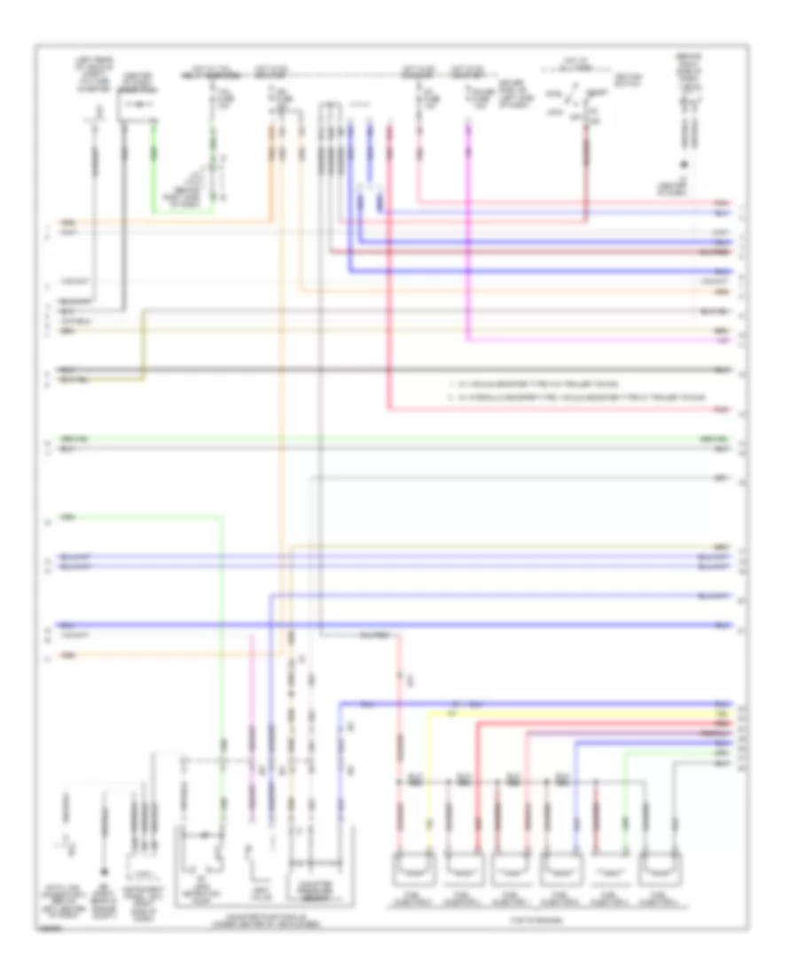
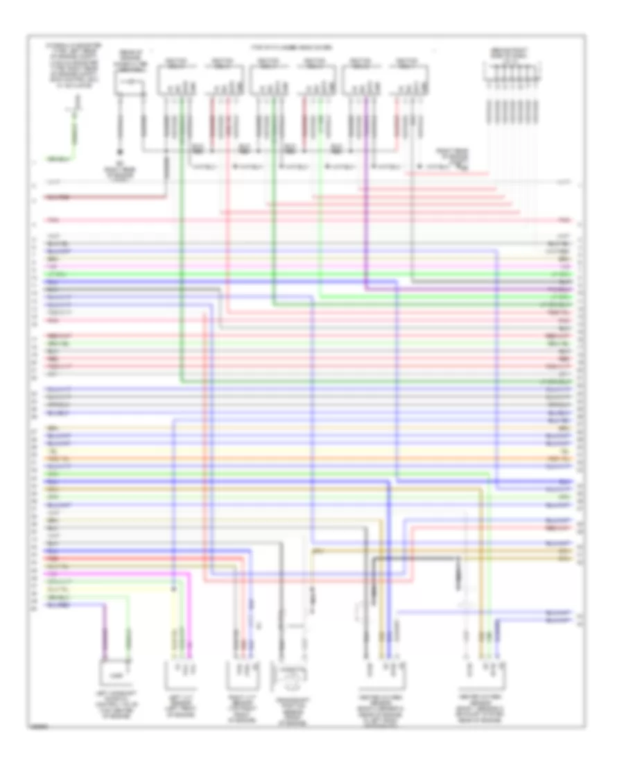
2.7L, Engine Performance Wiring Diagram (2 of 7) for Toyota Tacoma X-Runner 2013
List of elements for 2.7L, Engine Performance Wiring Diagram (2 of 7) for Toyota Tacoma X-Runner 2013:
- (behind right side of dash) j/c 4 & 5
- (top of engine)
- (under front passenger's seat) voltage inverter
- A17
- A18
- Acc
- B10
- B11
- C13
- Canister pressure sensor
- Canister pump module (under center of vehicle bed)
- Driver side j/b (left side of dash)
- Ea1
- Eh (rear of cylinder head)
- Fuel injector 1
- Fuel injector 2
- Fuel injector 3
- Fuel injector 4
- Gauge fuse 7.5a
- Hot at all times
- Hot in on or start
- Hot w/ tail relay energized
- I15
- Ib1
- Id2
- Ig2
- Ign fuse 15a
- Ignition switch
- Ih1
- Im1
- Instrument panel j/b 2 (right side of dash)
- Leak detection pump
- Lock
- Off
- Out
- Red
- Start
- Tail fuse 10a
- Vent valve
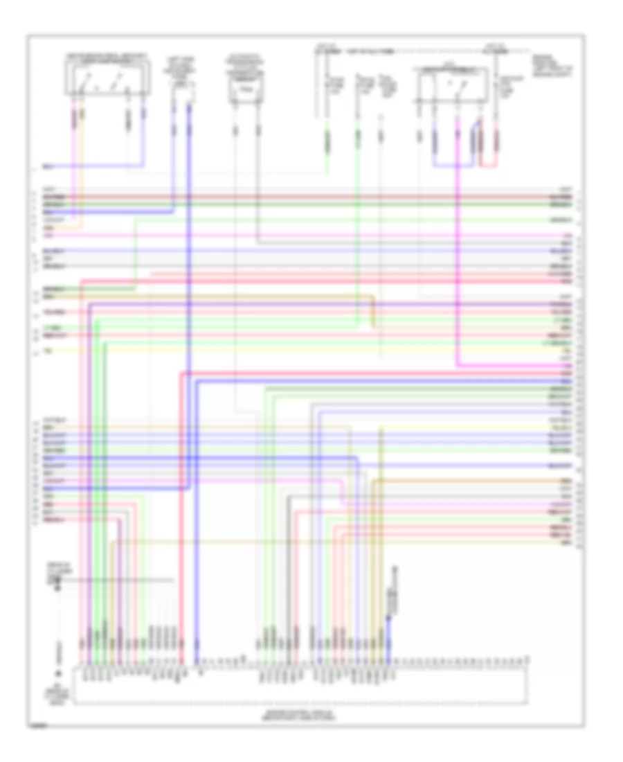
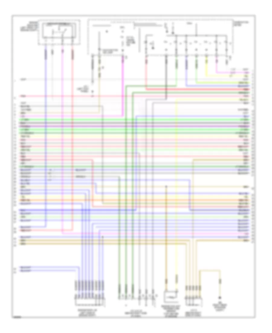
2.7L, Engine Performance Wiring Diagram (3 of 7) for Toyota Tacoma X-Runner 2013
List of elements for 2.7L, Engine Performance Wiring Diagram (3 of 7) for Toyota Tacoma X-Runner 2013:
- (a/t) air pump htr relay
- (above brake pedal bracket) stop lamp switch
- (automatic transmission) a/t fluid temperature sensor
- (left side of dash) instrument panel j/b 1
- (rear of cylinder head) eg
- Air pump fuse 50a
- Air pump htr fuse 10a
- Alt
- Charging system starting/
- E01
- E02
- E17
- E20
- E2g
- Eh (rear of cylinder head)
- Eknk
- Engine control module (behind right side of dash)
- Engine room r/b (left front of engine compt)
- Eppm
- Eta
- Etcs fuse 10a
- Etha
- Ethw
- Hot at all times
- Igf1
- Igt1
- Igt2
- Igt3
- Igt4
- Knk1
- Me01
- Pnk
- Ppmp
- Red
- Stop fuse 10a
- Tha
- Thoc
- Thw
- Vcpp
- Vcta
- Vta1
- Vta2
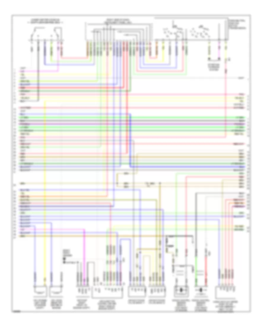
2.7L, Engine Performance Wiring Diagram (4 of 7) for Toyota Tacoma X-Runner 2013
List of elements for 2.7L, Engine Performance Wiring Diagram (4 of 7) for Toyota Tacoma X-Runner 2013:
- (behind right side of dash) j/c 12
- (left top of engine) throttle body assembly
- (rear of cylinder head) eh
- (right side of engine compt)
- (top of cylinder head cover)
- (top of engine)
- A/t
- Air injection control driver
- Air pump (right front of engine compt)
- Air switching valve (right side of engine compt)
- Aphg
- Apht
- Bat
- E2g
- Ea (right front fender)
- Ea1
- Ef1
- Eh (rear of cylinder head)
- Gnd
- Ia1
- Igf
- Ignition coil 1
- Ignition coil 2
- Ignition coil 3
- Ignition coil 4
- Igt1
- Igt2
- Igt3
- Igt4
- Knock control sensor (bank 1) (left side of engine)
- M/t
- Mass air flow meter (part of air intake assembly, next to air cleaner box)
- Nca
- Noise filter (ignition)
- Pnk
- Sip
- Siv
- Tha
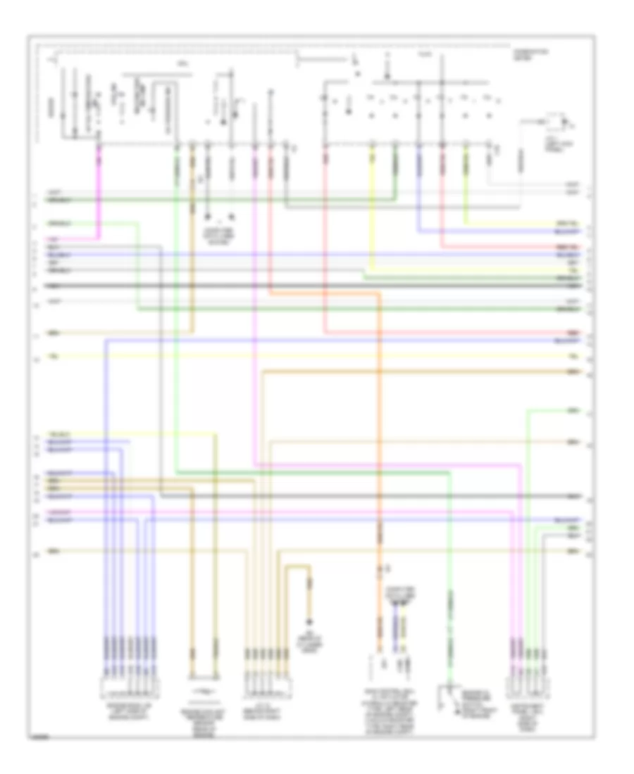
2.7L, Engine Performance Wiring Diagram (5 of 7) for Toyota Tacoma X-Runner 2013
List of elements for 2.7L, Engine Performance Wiring Diagram (5 of 7) for Toyota Tacoma X-Runner 2013:
- A/t oil temperature
- A12
- A13
- A14
- A15
- A18
- B10
- Buzzer
- C10
- C12
- Canh
- Canl
- Combination meter
- Computer data lines system
- Cpu
- Eh (rear of cylinder head)
- Engine coolant temperature sensor (rear of engine)
- Engine oil pressure switch (right front of engine)
- Engine room j/b (left side of engine compt)
- Fuel ind
- Ia1
- Ind
- Ind lamp malfunction
- Instrument panel j/b 2 (right side of dash)
- J/c 1 (left kick panel)
- J/c 12 (behind right side of dash)
- Nca
- Oil pressure ind
- Red
- Skid control ecu w/ actuator (hydraulic booster type: left rear of engine compt) (vacuum booster type: right rear of engine compt)
- Sp1
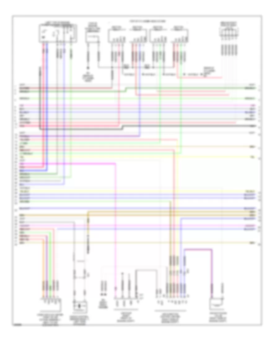
2.7L, Engine Performance Wiring Diagram (6 of 7) for Toyota Tacoma X-Runner 2013
List of elements for 2.7L, Engine Performance Wiring Diagram (6 of 7) for Toyota Tacoma X-Runner 2013:
- (right side of dash) instrument panel j/b 2
- (under center console) shift lock control ecu
- A10
- B11
- C11
- C13
- C14
- C16
- Camshaft position sensor (left side of engine)
- Camshaft timing oil control valve (front of engine)
- Crankshaft position sensor (front of engine)
- E12
- E15
- Gnd
- Ij1
- Nca
- Ne-
- Park/neutral position switch (transmission)
- Red
- Starting/ charging system
- Vsv (purge) (left side of engine compt)
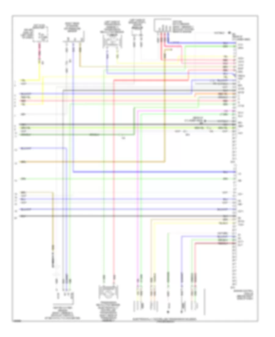
2.7L, Engine Performance Wiring Diagram (7 of 7) for Toyota Tacoma X-Runner 2013
List of elements for 2.7L, Engine Performance Wiring Diagram (7 of 7) for Toyota Tacoma X-Runner 2013:
- (left side of engine compt) engine room j/b
- (left side of transmission assembly) transmission revolution sensor (turbine)
- (rear of cylinder head) eg
- (right rear of engine) air pressure sensor
- A1a+
- A1a-
- Aip
- Air fuel ratio sensor (bank 1 sensor 1) (exhaust system, rear of engine)
- Driver side j/b (left side of dash)
- E03
- E04
- E18
- E19
- Ea1
- Eaip
- Eg (rear of cylinder head)
- Electronically controlled transmission solenoid (transmission)
- Engine control module (behind right side of dash)
- Etho
- Ex1b
- Ge01
- H13
- Ha1a
- Hai1
- Heated oxygen sensor (bank 1 sensor 2) (exhaust manifold, after catalytic converter)
- Hot in on or start
- Ht1b
- Ig1 fuse 10a
- Ih1
- Ih2
- Nc0-
- Nca
- Nco+
- Ne+
- Ne-
- Oc1+
- Oc1-
- Ox1b
- Pnk
- Prg &
- Red
- Slt+
- Slt-
- Slu+
- Slu-
- Sp2+
- Sp2-
- Tho1
- Transmission revolution sensor (electronically controlled transmission) (right rear of transmission assembly)
4.0L
4.0L, Engine Performance Wiring Diagram (1 of 7) for Toyota Tacoma X-Runner 2013
List of elements for 4.0L, Engine Performance Wiring Diagram (1 of 7) for Toyota Tacoma X-Runner 2013:
- (behind left side of dash)
- +b2
- 4wd
- A/f heater fuse 15a
- A/f heater relay
- A10
- A11
- A30
- A31
- A33
- Ac1
- Accelerator position sensor
- Act
- Aip
- Aip2
- Air conditioning system
- Anti-theft system
- Batt
- Bd (left rear frame rail)
- C/opn relay
- Canh
- Canl
- Ccs
- Computer data lines system
- Cruise control system
- Driver side j/b (left side of dash)
- E13
- E14
- Ea (right front fender)
- Eb (near battery)
- Efi fuse 10a
- Efi fuse 20a
- Efi relay
- Els
- Els2
- Engine control module (behind right side of dash)
- Engine room j/b (left side of engine compt)
- Engine room r/b (left front of engine compt)
- Epa
- Epa2
- F/ps
- Fpr
- Fuel pump relay
- Fuel pump resistor
- Fuel suction pump & gauge assembly (fuel tank)
- Hot at all times
- Ia1
- Ib1
- Igsw
- Ih1
- Im1
- Imi
- Imo
- Instrument cluster system
- Mpmp
- Mrel
- Red
- Spd
- St1-
- Sta
- Starting/charging system
- Stp
- Tach
- Thwo
- Transmissions system
- Vcp2
- Vcpa
- Vpa
- Vpa2
- Vpmp
4.0L, Engine Performance Wiring Diagram (2 of 7) for Toyota Tacoma X-Runner 2013
List of elements for 4.0L, Engine Performance Wiring Diagram (2 of 7) for Toyota Tacoma X-Runner 2013:
- (behind right side of dash) j/c 5
- (center of dash) diode (tail)
- (left rear of vehicle compt) voltage inverter
- (top of engine)
- A18
- Acc
- B10
- B11
- C13
- Canister pressure sensor
- Canister pump module (under center of vehicle bed)
- Data link connector 3 (below left center of dash)
- Driver side j/b (left side of dash)
- Ea1
- Ee (right rear of engine compt)
- Fuel injector 1
- Fuel injector 2
- Fuel injector 3
- Fuel injector 4
- Fuel injector 5
- Fuel injector 6
- Gauge fuse 7.5a
- H13
- Hot at all times
- Hot in on or start
- Hot w/ tail relay energized
- I15
- Ib1
- Ic (center of dash)
- Id2
- If1
- Ig1 fuse 10a
- Ig2
- Ign fuse 15a
- Ignition switch
- Ih1
- Instrument panel j/b 2 (right side of dash)
- J/c 4 & 5 (behind right side of dash)
- Leak detection pump
- Lock
- Off
- Out
- Pnk
- Red
- Start
- Tail fuse 10a
- Vent valve
- W/ hydraulic booster type, vacuum booster type w/ trailer towing
- W/ vacuum booster type w/o trailer towing
4.0L, Engine Performance Wiring Diagram (3 of 7) for Toyota Tacoma X-Runner 2013
List of elements for 4.0L, Engine Performance Wiring Diagram (3 of 7) for Toyota Tacoma X-Runner 2013:
- (above brake pedal bracket) stop lamp switch
- (left side of dash) instrument panel j/b 1
- (right side of dash) instrument panel j/b 2
- A/pump fuse 50a
- Ai valve fuse 10a
- Ai valve relay
- Airv
- E01
- E02
- E03
- E04
- E05
- E12
- Ea1
- Ee (right rear of engine compt)
- Ef (left rear of engine compt)
- Engine control module (behind right side of dash)
- Engine room r/b (left front of engine compt)
- Etcs fuse 10a
- Ex1b
- Ex2b
- Ha1a
- Ha2a
- Hot at all times
- Ht1b
- Ht2b
- Ia3
- If1
- Me01
- Ne+
- Ne-
- Oc2+
- Oc2-
- Ox1b
- Ox2b
- Pnk
- Red
- Stop fuse 10a
- Stop lp ctrl relay
- Vcv1
- Vcv2
- Vv1+
- Vv1-
- Vv2+
- Vv2-
- W/ hydraulic booster type, vacuum booster type w/ trailer towing
- W/ vacuum booster type w/o trailer towing
4.0L, Engine Performance Wiring Diagram (4 of 7) for Toyota Tacoma X-Runner 2013
List of elements for 4.0L, Engine Performance Wiring Diagram (4 of 7) for Toyota Tacoma X-Runner 2013:
- (behind right side of dash) j/c 12
- (hydraulic booster type: left rear of engine compt) (vacuum booster type: right rear of engine compt) skid control ecu w/ actuator
- (rear of engine)
- (right rear of engine compt) ee
- (top of cylinder head cover)
- Crankshaft position sensor (front of engine)
- Ed (right rear of engine compt)
- Gnd
- Heated oxygen sensor (bank 1 sensor 2) (exhaust system, rear of engine)
- Heated oxygen sensor (bank 2 sensor 2) (rear of engine, in left bank of exhaust)
- Ht1b
- Ht2b
- If1
- Igf
- Ignition coil 1
- Ignition coil 2
- Ignition coil 3
- Ignition coil 4
- Ignition coil 5
- Ignition coil 6
- Igt1
- Igt2
- Igt3
- Igt4
- Igt5
- Igt6
- Left camshaft timing oil control valve (top center of engine)
- Left vvt sensor (left front of engine)
- Nca
- Noise filter (ignition)
- Ox1b
- Ox2b
- Pnk
- Red
- Right vvt sensor (top right front of engine)
- Stpo
- Vvl+
- Vvl-
- Vvr+
- Vvr-
4.0L, Engine Performance Wiring Diagram (5 of 7) for Toyota Tacoma X-Runner 2013
List of elements for 4.0L, Engine Performance Wiring Diagram (5 of 7) for Toyota Tacoma X-Runner 2013:
- A/t oil tempe- rature ind
- A13
- A14
- A15
- A18
- Air pump htr relay
- B10
- C10
- Combination meter
- Cpu
- Ee (right rear of engine compt)
- Engine coolant temperature sensor (top center of engine)
- Engine room j/b (left side of engine compt)
- Engine room r/b (left front of engine compt)
- Ih1
- Ii1
- Ij1
- J/c 1 (left kick panel)
- J/c 12 (behind right side of dash)
- J/c j4 & j5 (behind right side of dash)
- Malfunction ind lamp
- Pnk
- Red
4.0L, Engine Performance Wiring Diagram (6 of 7) for Toyota Tacoma X-Runner 2013
List of elements for 4.0L, Engine Performance Wiring Diagram (6 of 7) for Toyota Tacoma X-Runner 2013:
- (right front fender) ea
- (right side of dash) instrument panel j/b 2
- (right side of engine compt)
- (under center console) shift lock control ecu
- +bl
- A10
- A20
- Aip
- Aip2
- Air injection control driver
- Air pump (right front of engine compt)
- Air switching valve (bank 1)
- Air switching valve (bank 2)
- Aph+
- Aphg
- B11
- B12
- Bat
- C11
- C14
- E11
- E14
- E15
- E22
- E2g
- Ea1
- Ee2
- Gnd
- Gndl
- If1
- Ih1
- Knock control sensor (bank 1) (top front of engine)
- Knock control sensor (bank 2) (top front of engine)
- Mass air flow meter (part of air intake assembly, next to air cleaner box)
- Nca
- Park/neutral position switch (transmission)
- Pnk
- Red
- Sip
- Siv
- Starting/ charging system
- Tha
- Vc2
- Vsv (acis) (rear top center of engine)
- Vsv (purge) (left side of engine compt)
4.0L, Engine Performance Wiring Diagram (7 of 7) for Toyota Tacoma X-Runner 2013
List of elements for 4.0L, Engine Performance Wiring Diagram (7 of 7) for Toyota Tacoma X-Runner 2013:
- (exhaust system, rear of engine) air fuel ratio sensor (bank 1 sensor 1)
- (front top of engine) throttle body assembly
- (left side of engine compt) engine room j/b
- (right rear of engine compt) ee
- (right rear of engine) air fuel ratio sensor (bank 2 sensor 1)
- (right rear of transmission assembly) transmission revolution sensor (electronically controlled transmission)
- +bm
- A1a+
- A1a-
- A2a+
- A2a-
- Acis
- Aidi
- Airi
- Airp
- E10
- E11
- E2g
- Ea1
- Ekn2
- Eknk
- Electronically controlled transmission solenoid (transmission)
- Engine control module (behind right side of dash)
- Eta
- Etha
- Ethw
- Ge01
- Ha1a
- Ha2a
- Hai1
- If1
- Igf1
- Igt1
- Igt2
- Igt3
- Igt4
- Igt5
- Igt6
- Knk1
- Knk2
- Nca
- Nsw
- Nt+
- Nt-
- Oc1+
- Oc1-
- Pnk
- Power steering oil pressure switch (power steering pump)
- Ppmp
- Prg
- Psw
- Red
- Right camshaft timing oil control valve (top center of engine)
- Sl1+
- Sl1-
- Sl2+
- Sl2-
- Slt+
- Slt-
- Slu+
- Slu-
- Sp2+
- Sp2-
- Starting/charging system
- Th01
- Th02
- Tha
- Thw
- Transmission revolution sensor (turbine) (left side of transmission assembly)
- Vcta
- Vta1
- Vta2
EXTERIOR LIGHTS
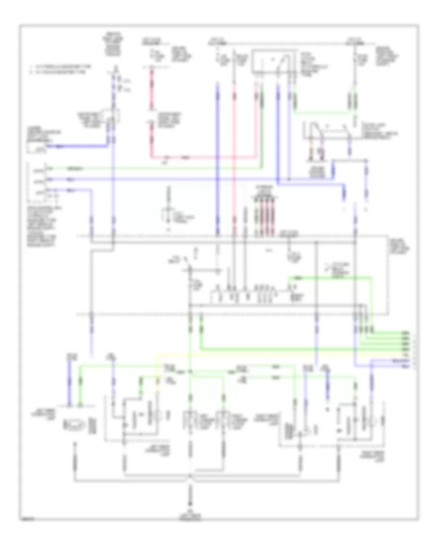
Backup Lamps Wiring Diagram for Toyota Tacoma X-Runner 2013
List of elements for Backup Lamps Wiring Diagram for Toyota Tacoma X-Runner 2013:
- 2.7l
- 4.0l
- A/t
- B/up
- B11
- Backup lamp
- Backup lamp relay (behind right side of dash)
- Backup lamp switch (right side of transmission)
- Bd (left rear frame rail)
- Be1
- Bkup lp fuse 10a
- C10
- C17
- Combination meter
- Driver side j/b (left side of dash)
- E19
- Engine control module (behind right side of dash)
- Except tmmtx made
- H11
- H13
- Hot in on or start
- Id2
- Ig1 fuse 10a
- Ih1
- In1
- In2
- Inner rear view mirror
- Instrument panel j/b 2 (right side of dash)
- Ip1
- J/c 13 (behind right kick panel)
- Left rear combin- -ation lamp
- M/t
- Park/ neutral position switch (transmission)
- Pnk
- Red
- Rev
- Right rear combin- -ation lamp
- Tmmtx made
- Trailer socket (left kick panel)
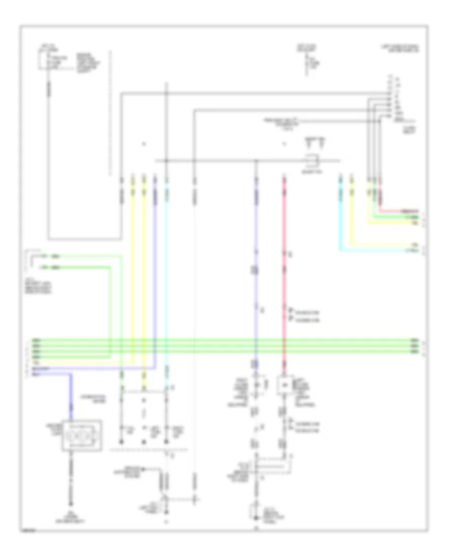
Exterior Lamps Wiring Diagram, with Trailer Tow (1 of 4) for Toyota Tacoma X-Runner 2013
List of elements for Exterior Lamps Wiring Diagram, with Trailer Tow (1 of 4) for Toyota Tacoma X-Runner 2013:
- (hydraulic booster type: left rear of engine compt) (vacuum booster type: right rear of engine compt) skid control ecu w/ actuator
- Bd (left rear frame rail)
- Be2
- Body ecu
- Bulb type
- C11
- C15
- C16
- Cruise control system
- D10
- D13
- Dcty
- Driver side j/b (left side of dash)
- Drl
- Ecu-b fuse 7.5a
- Ecub
- Engine room r/b (left front of engine compt)
- Gnd
- H18
- Haz
- Hot at all times
- Hot in on or start
- I10
- Ia3
- Ig1 2 fuse 10a
- Ig1 fuse 10a
- Instrument panel j/b 2 (right side of dash)
- Interior lights system
- J/b fuse 50a
- J/c 1 (left kick panel)
- J15
- J19
- Led type
- Left license plate lamp
- Left rear combination lamp
- Pcty
- Pnk
- Rcty
- Red
- Right license plate lamp
- Right rear combination lamp
- Side marker
- Stop
- Stop fuse 10a
- Stop lamp switch (bracket, above brake pedal)
- Stop lp ctrl relay
- Stp
- Stp2
- Stpo
- Tail
- Tail fuse 10a
- Tail relay
- Tail/side marker
- Tail/stop
- To driver side j/b (diagram 3 of 4)
- Trly
- Turn
- W/ hydraulic booster type
- W/ vacuum booster type
Exterior Lamps Wiring Diagram, with Trailer Tow (2 of 4) for Toyota Tacoma X-Runner 2013
List of elements for Exterior Lamps Wiring Diagram, with Trailer Tow (2 of 4) for Toyota Tacoma X-Runner 2013:
- (behind right side of dash) (except usa) j/c 4
- (behind right side of dash) engine control module
- (under center console) shift lock control ecu
- 2.7l
- 4.0l
- Access cab
- B13
- Ba (under driver's seat)
- C18
- Center stop lamp
- Combination meter
- D11
- Double cab
- Driver side j/b (left side of dash)
- E14
- E22
- Ground distribution system
- H18
- I11
- I12
- Ia3
- Ic1
- Ic7
- Ik4
- Instrument panel j/b 1 (left side of dash)
- Ir1
- J/c 1 (left kick panel)
- J/c 2 (behind left side of dash)
- J/c j13 (behind right kick panel)
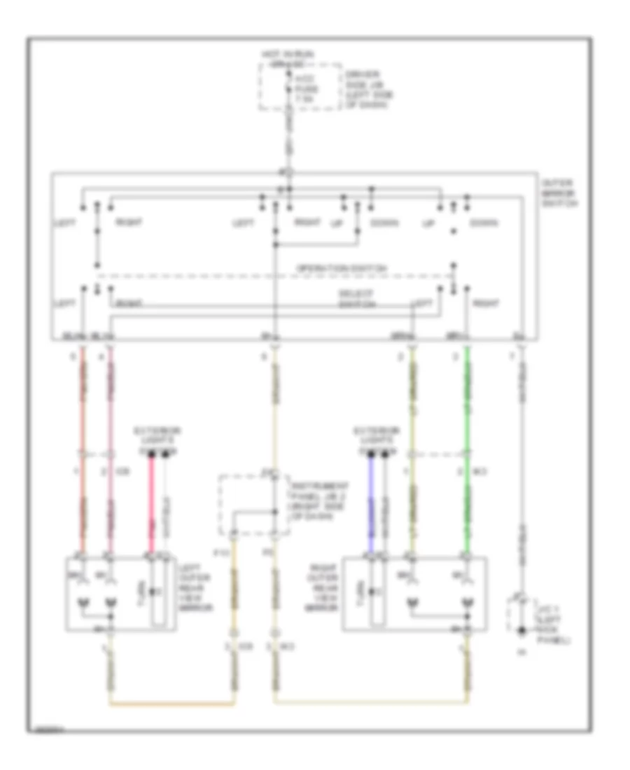
- Left outer mirror turn view mirror (if equipped)
- Left turn ind
- Pnk
- Right outer mirror view mirror (if equipped)
- Right turn ind
- Stp
- Tail ind
- Turn
Exterior Lamps Wiring Diagram, with Trailer Tow (3 of 4) for Toyota Tacoma X-Runner 2013
List of elements for Exterior Lamps Wiring Diagram, with Trailer Tow (3 of 4) for Toyota Tacoma X-Runner 2013:
- C11
- Combination switch
- Driver side j/b (left side of dash)
- Drl
- Engine room r/b (left front of engine compt)
- From body ecu (diagram 1 of 4)
- Haz
- Hazard switch
- Hazard warning signal switch assembly
- Head
- Hot at all times
- Hot in on or start
- I20
- Ic (center of dash)
- Ig1 fuse 10a
- Ij1
- Ir1
- J/c 13 (behind right kick panel)
- J/c j4 & j5 (behind right side of dash)
- J11
- J18
- Left
- Light control switch
- Ltot
- Ltrn
- M10
- M11
- Off
- Pnk
- Red
- Right
- Rtot
- Rtrn
- Stin
- Tail
- Towing fuse 30a
- Trn & haz fuse 15a
- Turn signal flasher (left side of dash)
- Turn switch
- W/ drl
Exterior Lamps Wiring Diagram, with Trailer Tow (4 of 4) for Toyota Tacoma X-Runner 2013
List of elements for Exterior Lamps Wiring Diagram, with Trailer Tow (4 of 4) for Toyota Tacoma X-Runner 2013:
- A33
- A34
- A35
- A37
- B/up
- Backup lamps circuit
- Batt
- Batt chg fuse 30a
- Batt chg relay
- Bd (left rear frame rail)
- Be1
- Brk
- C13
- C14
- Driver side j/b (left side of dash)
- Ea (right front fender)
- Eb (near battery)
- Engine room j/b (left side of engine compt)
- Engine room r/b (left front of engine compt)
- Gnd
- H10
- H11
- Hot at all times
- Hot in on or start
- Ia4
- Ib1
- Id2
- Ig1 2 fuse 10a
- Instrument panel j/b 1 (left side of dash)
- Ir1
- J/c 1 (left kick panel)
- J/c j20 (left side of dash)
- Left headlight assembly
- Marker
- Parking
- Red
- Right headlight assembly
- Stop
- Sttl
- Sttr
- Tail
- Towing brake controller (left side of dash)
- Towing brk fuse 30a
- Towing tail fuse 30a
- Towing tail relay
- Trailer socket (if equipped) (left kick panel)
- Turn
Exterior Lamps Wiring Diagram, without Trailer Tow (1 of 3) for Toyota Tacoma X-Runner 2013
List of elements for Exterior Lamps Wiring Diagram, without Trailer Tow (1 of 3) for Toyota Tacoma X-Runner 2013:
- (behind right side of dash) engine control module
- (under center console) shift lock control ecu
- 2.7l
- 4.0l
- B13
- Bd (left rear frame rail)
- Bulb type
- C11
- C15
- C16
- Cruise control system
- D10
- D13
- Dcty
- Driver side j/b (left side of dash)
- E14
- E22
- Ecu-b fuse 7.5a
- Ecub
- Engine room r/b (left front of engine compt)
- Gnd
- H18
- Haz
- Hot at all times
- Hot in on or start
- Ia3
- Ig1 2 fuse 10a
- Ig1 fuse 10a
- Instrument panel j/b 1 (left side of dash)
- Instrument panel j/b 2 (right side of dash)
- Interior lights system
- J/b fuse 50a
- J/c 1 (left kick panel)
- J15
- Led type
- Left license plate lamp
- Left rear combination lamp
- Pcty
- Pnk
- Rcty
- Red
- Right license plate lamp
- Right rear combination lamp
- Side marker
- Skid control ecu w/ actuator (hydraulic booster type: left rear of engine compt) (vacuum booster type: right rear of engine compt)
- Stop
- Stop fuse 10a
- Stop lamp switch (bracket, above brake pedal)
- Stop lp ctrl relay (w/ hydraulic booster type)
- Stp
- Stp2
- Stpo
- Tail body ecu
- Tail fuse 10a
- Tail relay
- Tail/side marker
- Tail/stop
- To flash relay (diagram 2 of 3)
- Trly
- Turn
- W/ hydraulic booster type
- W/ vacuum booster type
Exterior Lamps Wiring Diagram, without Trailer Tow (2 of 3) for Toyota Tacoma X-Runner 2013
List of elements for Exterior Lamps Wiring Diagram, without Trailer Tow (2 of 3) for Toyota Tacoma X-Runner 2013:
- (left side of dash) driver side j/b
- Access cab
- Ba (under driver's seat)
- C18
- Center stop lamp
- Combination meter
- D11
- Double cab
- Ehw
- Engine room r/b (left front of engine compt)
- Flash relay
- From body ecu (diagram 1 of 3)
- Gnd
- Ground distribution system
- H18
- Hot at all times
- Hot in on or start
- I11
- I12
- Ia3
- Ic1
- Ic7
- Ig1 fuse 10a
- Ik4
- J/c 1 (left kick panel)
- J/c 13 (behind right kick panel)
- J/c 4 (except usa) (behind right side of dash)
- J/c j4 & j5 (behind right side of dash)
- J11
- J18
- Left outer mirror turn view mirror (if equipped)
- Left turn ind
- Pnk
- Right outer mirror view mirror (if equipped)
- Right turn ind
- Short pin
- Tail ind
- Trn-haz fuse 15a
- Turn
Exterior Lamps Wiring Diagram, without Trailer Tow (3 of 3) for Toyota Tacoma X-Runner 2013
List of elements for Exterior Lamps Wiring Diagram, without Trailer Tow (3 of 3) for Toyota Tacoma X-Runner 2013:
- A33
- A35
- A37
- C11
- Combination switch
- Ea (right front fender)
- Eb (near battery)
- Engine room j/b (left side of engine compt)
- H10
- H11
- Hazard switch
- Hazard warning signal switch assembly
- Head
- Ic (center of dash)
- Ij1
- J/c 13 (behind right kick panel)
- J/c j20 (left side of dash)
- J/c j4 & j5 (behind right side of dash)
- Left
- Left headlight turn assembly
- Light control switch
- Marker
- Off
- Parking
- Right
- Right headlight turn assembly
- Tail
- Turn signal switch
GROUND DISTRIBUTION
Ground Distribution Wiring Diagram (1 of 4) for Toyota Tacoma X-Runner 2013
List of elements for Ground Distribution Wiring Diagram (1 of 4) for Toyota Tacoma X-Runner 2013:
- (4wd) (4wd position) transfer indicator switch
- (4wd) (l4 position) transfer indicator switch
- (4wd) add actuator assembly
- (4wd) transfer shift actuator assembly
- (w/ cruise control) spiral cable
- 2.7l
- 4.0l
- A17
- A18
- A19
- Air fuel ratio sensor (bank 1 sensor 1) shield
- Air fuel ratio sensor (bank 2 sensor 1) shield
- Air switching valve
- Air switching valve (bank 1)
- Air switching valve (bank 2)
- Camshaft position sensor shield
- Canister pump module
- Crank- shaft position sensor shield
- Crankshaft position sensor shield
- Data link connector 3
- E11
- E12
- E19
- E20
- Ec1
- Ee (4.0l) (right rear of engine compt)
- Ef (4.0l) (left rear of engine compt)
- Eg (2.7l) (rear of cylinder head)
- Eh (2.7l) (rear of cylinder head)
- Engine control module
- From instrument panel j/b 2 (diagram 1 of 4)
- Heated oxygen sensor (bank 1 sensor 2) shield
- Heated oxygen sensor (bank 2 sensor 2) shield
- Id2
- Ignition coil 1
- Ignition coil 2
- Ignition coil 3
- Ignition coil 4
- Ignition coil 5
- Ignition coil 6
- Instrument panel j/b 2 (right side of dash)
- Junction connector (behind right side of dash)
- Knock control sensor (bank 1) shield
- Knock control sensor (bank 2) shield
- Nca
- Noise filter (ignition)
- To ground ee (diagram 1 of 4)
Ground Distribution Wiring Diagram (2 of 4) for Toyota Tacoma X-Runner 2013
List of elements for Ground Distribution Wiring Diagram (2 of 4) for Toyota Tacoma X-Runner 2013:
- (120v) rear power point socket assembly
- (120v) voltage inverter
- (2.7l) engine control module
- (2wd)
- (4wd)
- (access cab) right rear lower side door courtesy switch
- (access cab) right rear upper side door courtesy switch
- (if equipped) downhill assist control switch
- (w/ bench seat)
- (w/ built-in type amplifier) radio receiver assembly
- (w/ built-in type amplifier) speaker (woofer)
- (w/ separate seat)
- (w/ separate type amplifier) radio & display receiver assembly
- (w/ separate type amplifier) stereo component amplifier
- 4.0l
- 4wd control ecu
- A/c amplifier
- A/c control assembly
- A15
- A21
- A33
- Access cab
- Access cab w/ speaker (woofer)
- Air bag sensor assembly center
- Backup lamp relay
- Bb (under front passenger's seat)
- Bc (under front passenger's seat)
- Bc2
- Bf (right "c" pillar)
- Bg1
- Bh1
- Bj2
- Blower resistor
- Damper servo motor (air mix)
- Damper servo motor (air vent mode)
- Door control receiver
- Door lock control switch
- Double cab
- E21
- Ed (4.0l) (right rear of engine compt)
- F12
- Front passenger's side door lock assembly
- Hazard warning signal switch assembly
- Ib (center of dash)
- Ic1
- Ic7
- Id (under front of center console)
- Ie (right kick panel)
- Ik3
- Ik4
- Il1
- J16
- J17
- Junction connector
- Junction connector (behind right kick panel)
- Junction connector 16 & 17 (behind right side of dash)
- Junction connector 4 & 5 (behind right side of dash)
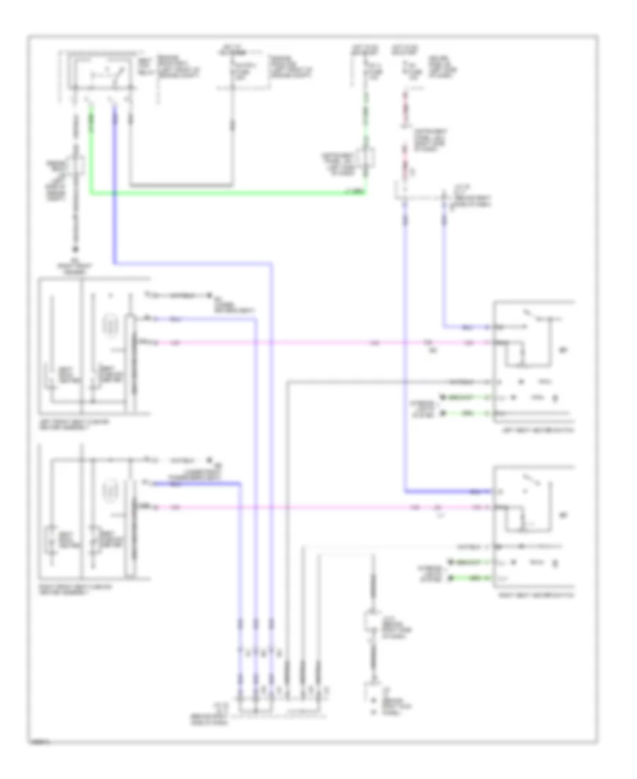
- Left outer rear view mirror
- Left seat heater switch
- Noise filter (ignition)
- Occupant classification ecu
- R16
- Right front seat cushion heater assembly
- Right outer rear view mirror
- Right seat heater switch
- S24
- Steering sensor
- Traction control switch
- W/ drl
- W/ outer rear view mirror side turn signal light
Ground Distribution Wiring Diagram (3 of 4) for Toyota Tacoma X-Runner 2013
List of elements for Ground Distribution Wiring Diagram (3 of 4) for Toyota Tacoma X-Runner 2013:
- (12v) acc skt relay
- (12v) front power outlet socket 1 (power point socket assembly)
- (12v) front power outlet socket 2 (power point socket assembly)
- (access cab) left rear lower side door courtesy switch
- (access cab) left rear upper side door courtesy switch
- (double & access cab) map lamp
- (if equipped) towing brake controller
- (if equipped) trailer socket
- (w/ trailer towing)
- A21
- Access cab
- Air bag sensor assembly center
- Ba (under driver's seat)
- Bd (left rear frame rail)
- Bd1
- Be (left "b" pillar)
- Be1
- Be2
- Bf1
- Bi2
- Body ecu
- C13
- Center room lamp
- Center stop lamp
- Combination meter
- Combination switch
- Data link connector
- Differential lock shift actuator assembly
- Double cab
- Driver side j/b (left side of dash)
- Driver's side door lock assembly
- Driver's side front seat inner belt
- E11
- E12
- E13
- Except tmmtx made
- F10
- F11
- Flash relay
- Fuel suction pump & gauge assembly
- H18
- H19
- Ia (left kick panel)
- Ic1
- Ic6
- Ic7
- Inner rear view mirror
- Ip1
- Junction connector 1
- Left front seat cushion heater assembly
- Left license plate lamp
- Left rear combination lamp
- Left vanity light (left visor assembly)
- O11
- O12
- O13
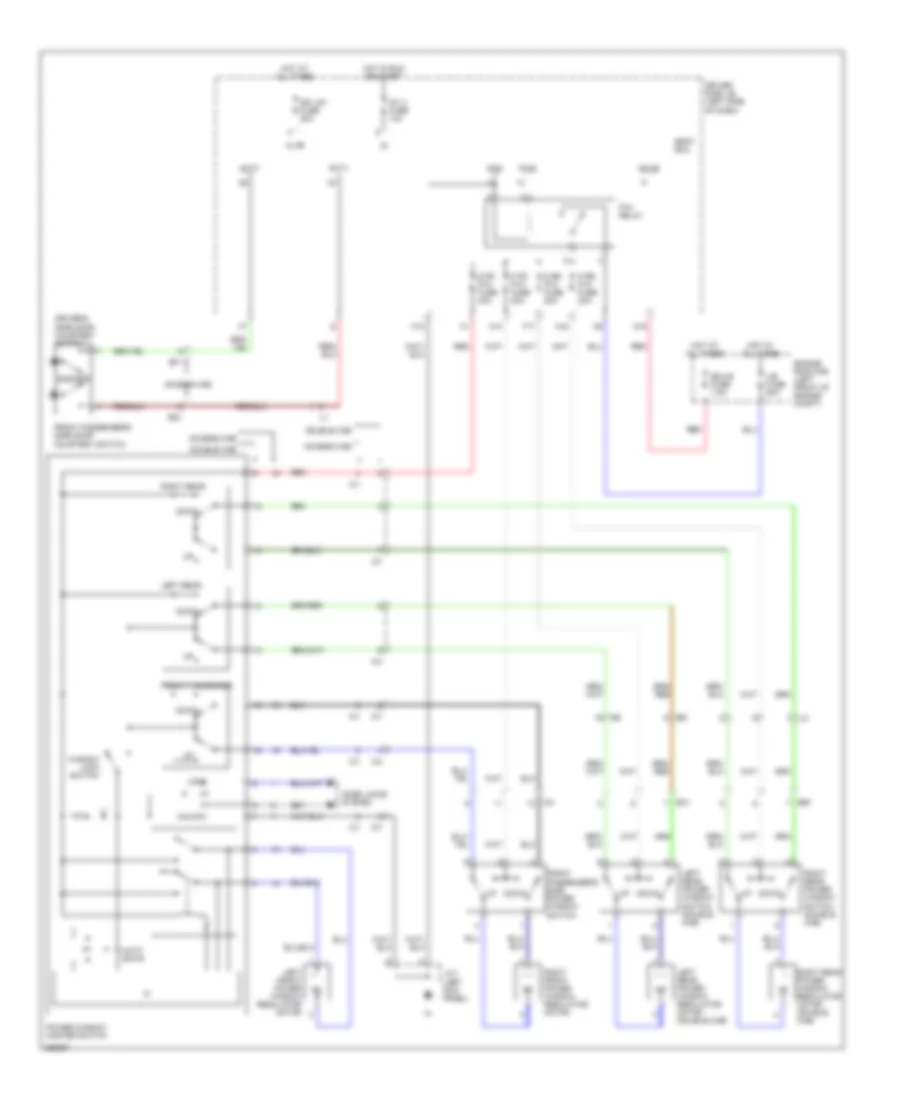
- Outer mirror switch
- P/w relay
- Power window master switch
- Rear differential transfer indicator switch
- Rheostat
- Right license plate lamp
- Right rear combination lamp
- Right vanity light (right visor assembly)
- Tire pressure warning ecu
- Tmmtx made
- To ground ic (diagram 4 of 4)
- Turn signal flasher
- Unlock warning switch
- W/ bench seat
- W/ drl
- W/ vanity light
- Yaw rate sensor
Ground Distribution Wiring Diagram (4 of 4) for Toyota Tacoma X-Runner 2013
List of elements for Ground Distribution Wiring Diagram (4 of 4) for Toyota Tacoma X-Runner 2013:
- (4.0l) engine control module
- (4wd m/t) clutch start cancel switch
- (4wd w/ vacuum booster type) skid control ecu w/ actuator
- (a/t) key interlock solenoid
- (a/t) shift lock control ecu
- (if equipped) 4wd control switch
- (w/ hydraulic booster type) skid control ecu w/ actuator
- (w/ hydraulic booster type) traction control switch
- (w/o door lock control) body ecu
- 2.7l m/t
- 4.0l & 2.7l a/t
- A/f heater relay
- A26
- A27
- A29
- A30
- A31
- A32
- A33
- A34
- A35
- A36
- A37
- A38
- A39
- Air injection control driver
- Air pump
- Batt chg relay
- Brake fluid level warning switch
- C11
- Combination switch
- Curtain airbag cut off switch
- E13
- Ea (right front fender)
- Eb (near battery)
- Efi main relay
- Engine room j/b (left side of engine compt)
- Engine room r/b (left front of engine compt)
- Engine room r/b 2 (left front of engine compt)
- Fog lamp switch
- From unlock warning switch (diagram 3 of 4)
- H10
- H11
- Heater relay
- Ia3
- Ic (center of dash)
- Junction connector 4 & 5 (behind right side of dash)
- Left front fog lamp
- Left headlight assembly
- Option connector (trailer socket)
- Pressure switch
- Right front fog lamp
- Right headlight assembly
- Seat htr relay
- Skid control ecu w/ actuator
- Sta relay
- Tire pressure warning reset switch
- Transponder key ecu
- W/ hydraulic booster type
- W/ vacuum booster type
- Windshield wiper motor
- Wireless door lock buzzer
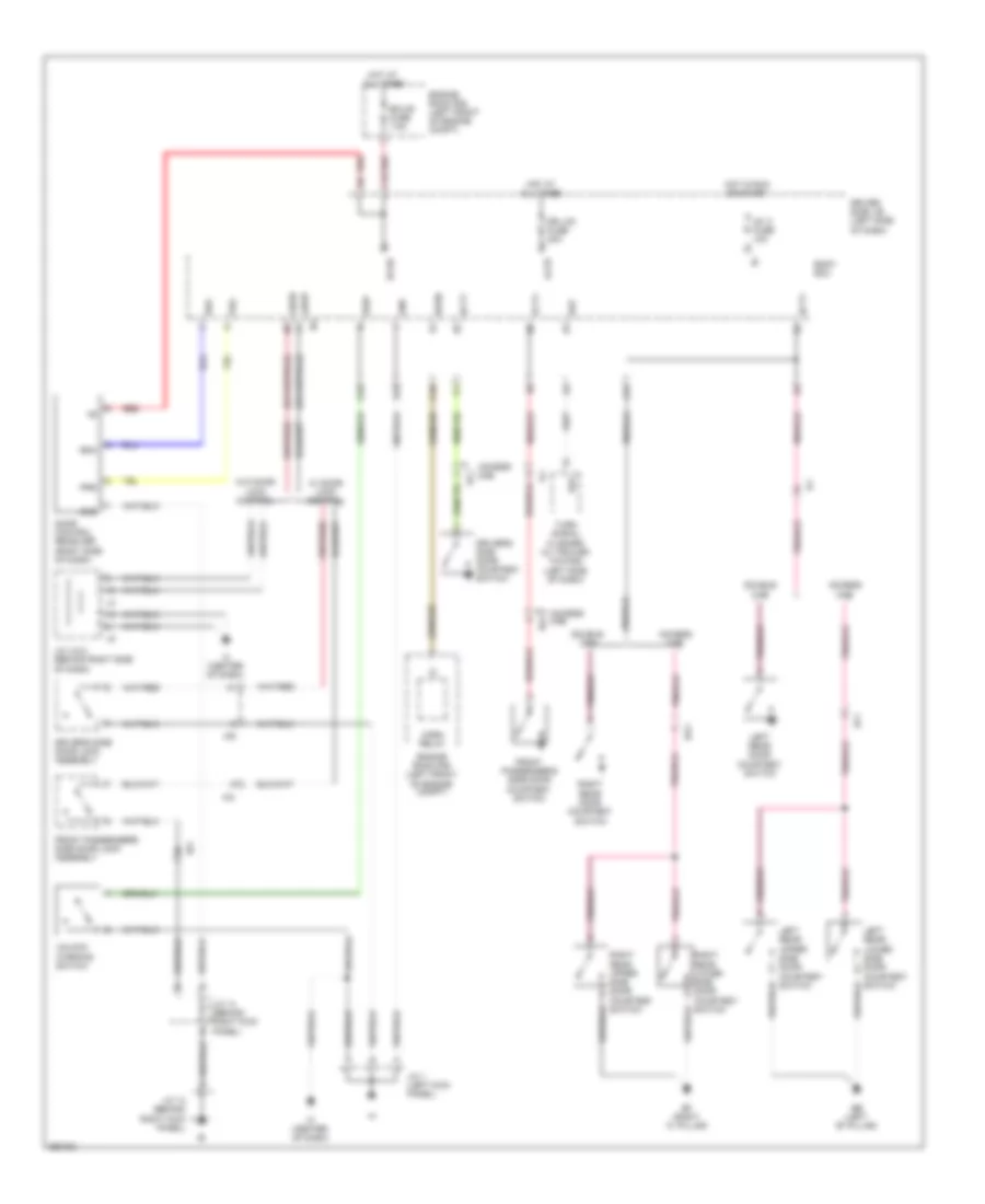
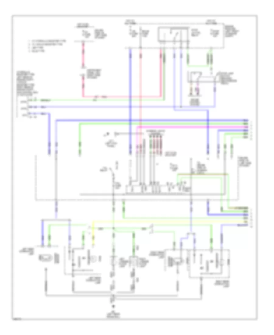
HEADLIGHTS
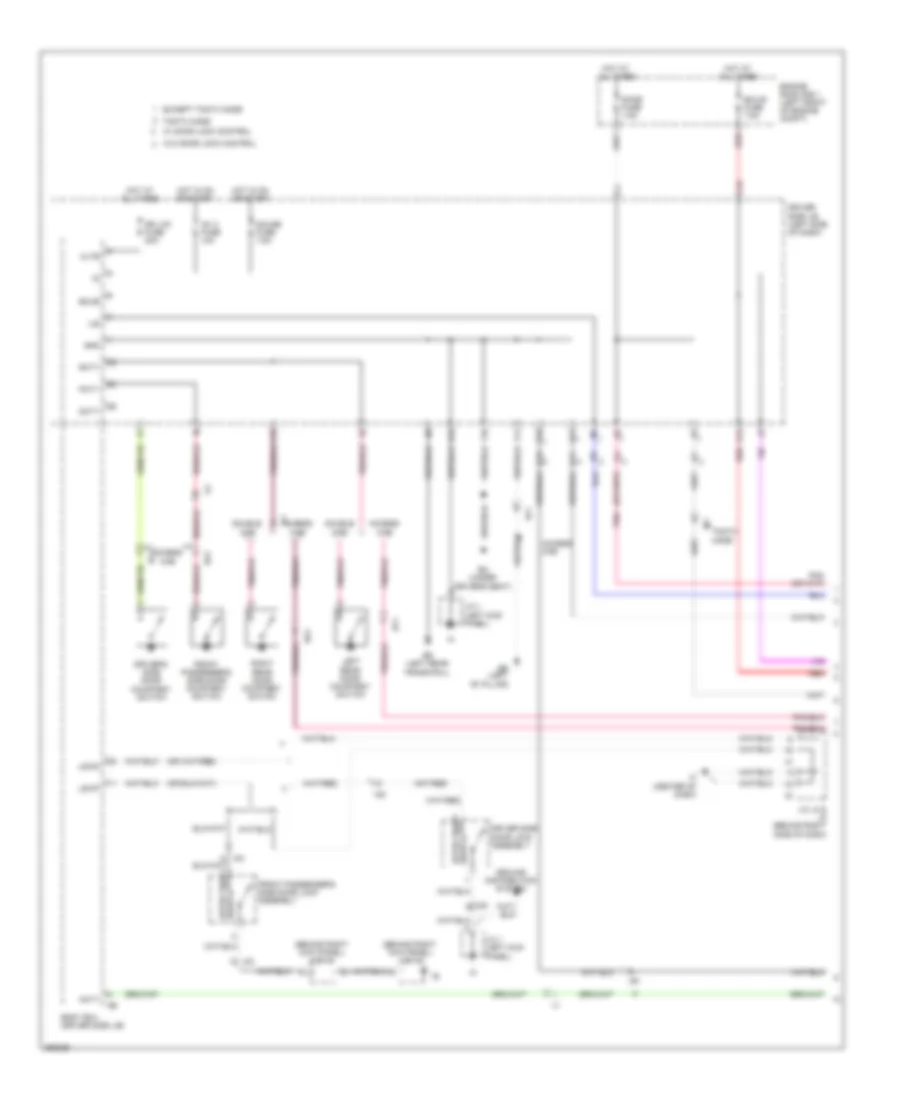
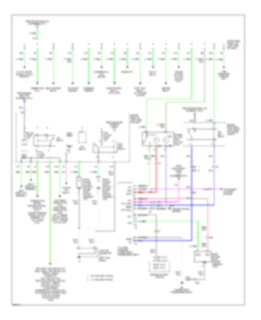
Headlights Wiring Diagram (1 of 2) for Toyota Tacoma X-Runner 2013
List of elements for Headlights Wiring Diagram (1 of 2) for Toyota Tacoma X-Runner 2013:
- (a/t)
- (left side of engine compt) engine room j/b
- (m/t)
- A19
- A20
- A21
- A22
- A33
- A38
- Altb
- Body ecu
- C10
- C11
- C15
- C16
- Combination meter
- Combination switch
- D11
- Dcty
- Dim
- Dim relay
- Dimmer switch
- Dr lck fuse 20a
- Driver side j/b (left side of dash)
- Drl
- Ea (right front fender)
- Eb (near battery)
- Ecu-b fuse 7.5a
- Ecub
- Engine room j/b (left side of engine compt)
- Engine room r/b (left front of engine compt)
- Exterior lights system
- Flash
- Fr fog fuse 15a
- Gnd
- Ground distribution system
- H-lp lh-hi fuse 10a
- H-lp lh-lo fuse 10a
- H-lp rh-hi fuse 10a
- H-lp rh-lo fuse 10a
- H18
- Head
- Head ind (usa)
- Head relay
- High
- High beam ind
- Hot at all times
- Hot in on or start
- Hrly
- I20
- Ia1
- Ic (center of dash)
- Ig1 2 fuse 10a
- Ij1
- Instrument panel j/b 1 (left side of dash)
- Interior lights system
- J/c 1 (left kick panel)
- J/c j4 & j5 (behind right side of dash)
- J15
- Left headlight assembly
- Light control switch
- Low
- M10
- Off
- Parking brake switch (base of park brake lever)
- Pcty
- Pkb
- Pnk
- Rcty
- Red
- Right headlight assembly
- Starting/charging system
- Tail
- Trly
- Turn signal flasher (w/ daytime running light) (left side of dash)
- Usa
Headlights Wiring Diagram (2 of 2) for Toyota Tacoma X-Runner 2013
List of elements for Headlights Wiring Diagram (2 of 2) for Toyota Tacoma X-Runner 2013:
- A23
- A24
- A25
- A33
- A36
- Ea (right front fender)
- Eb (near battery)
- Engine room j/b (left side of engine compt)
- Engine room r/b 2 (left front of engine compt)
- Fog lamp switch
- Fr fog relay
- Ia1
- Ic (center of dash)
- Interior lights system
- J/c j4 & j5 (behind right j5
- Left front fog lamp
- Right front fog lamp
- Side of dash)
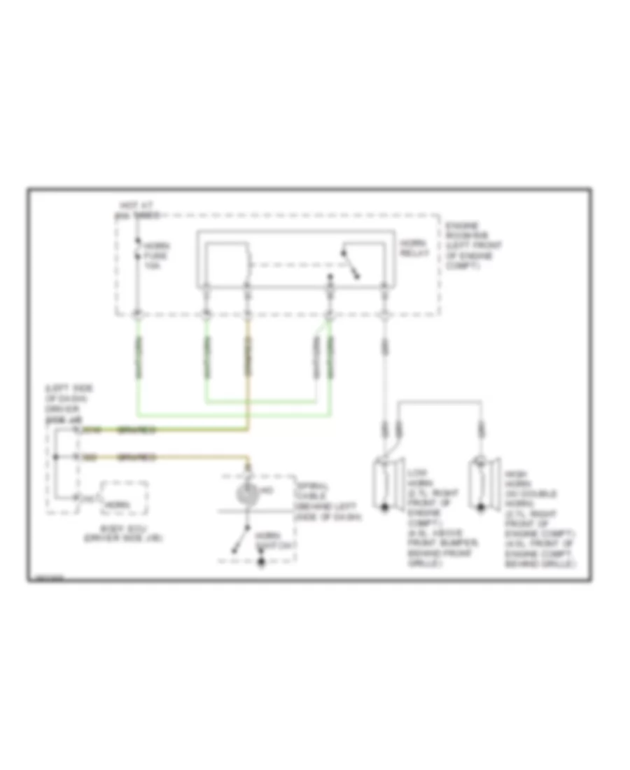
HORN
Horn Wiring Diagram for Toyota Tacoma X-Runner 2013
List of elements for Horn Wiring Diagram for Toyota Tacoma X-Runner 2013:
- (left side of dash) driver side j/b
- Body ecu (driver side j/b)
- C10
- Engine room r/b (left front of engine compt)
- High horn (w/ double horn) (2.7l: right front of engine compt) (4.0l: front of engine compt, behind grille)
- Horn
- Horn fuse 10a
- Horn relay
- Horn switch
- Hot at all times
- I22
- Low horn (2.7l: right front of engine compt) (4.0l: above front bumper, behind front grille)
- Spiral cable (behind left side of dash)
INSTRUMENT CLUSTER
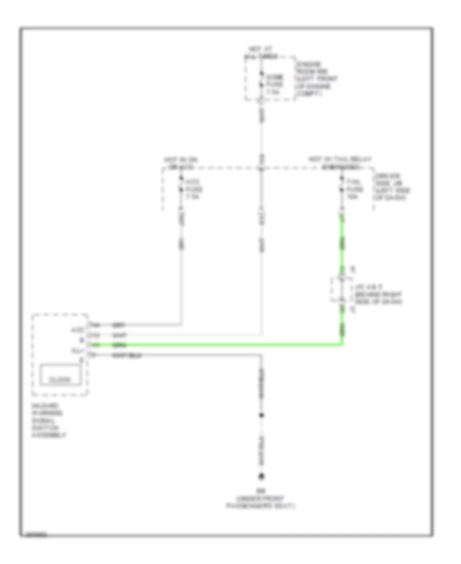
Clock Wiring Diagram for Toyota Tacoma X-Runner 2013
List of elements for Clock Wiring Diagram for Toyota Tacoma X-Runner 2013:
- Acc
- Acc fuse 7.5a
- Bb (under front passenger's seat)
- Clock
- Dome fuse 7.5a
- Driver side j/b (left side of dash)
- Engine room r/b (left front of engine compt)
- Hazard warning signal switch assembly
- Hot at all times
- Hot in on or acc
- Hot w/ tail relay energized
- Ill+
- J/c 4 & 5 (behind right side of dash)
- J20
- Tail fuse 10a
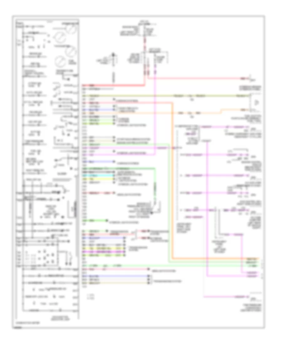
Instrument Cluster Wiring Diagram (1 of 2) for Toyota Tacoma X-Runner 2013
List of elements for Instrument Cluster Wiring Diagram (1 of 2) for Toyota Tacoma X-Runner 2013:
- (4.0l)
- (a/t)
- (except usa)
- (usa)
- 2.7l
- 2wd 4wd
- 4.0l
- 4lo ind
- 4wd control ecu (right side of dash)
- 4wd ind
- A-trac ind
- A/c amplifier (right side of dash)
- A/t
- A/t oil temp ind
- A10
- A11
- A12
- A13
- A14
- A15
- A16
- A17
- A18
- A19
- A20
- A21
- A22
- A23
- A24
- A25
- A26
- A27
- A28
- A29
- A30
- A31
- A32
- A33
- A34
- A35
- A36
- A37
- A38
- A39
- A40
- Abs ind
- Auto lsd ind
- B10
- B11
- B12
- B13
- B14
- B15
- B16
- B20
- Bat
- Brake ind
- Buzzer
- C10
- C12
- C16
- Canada
- Charge ind
- Combination meter
- Computer data lines system
- Cpu
- Cruise ind
- Door ind
- Downhill assist control ind
- Driver side j/b (left side of dash)
- Driver's seat belt ind
- E13
- E22
- Ecu-b fuse 7.5a
- Engine control module (behind right side of dash)
- Engine controls system
- Engine oil pressure switch (4.0l: center front of engine) (2.7l: right front of engine)
- Engine room r/b (left front of engine compt)
- Exterior lights system
- F10
- F12
- F14
- Fuel gauge
- Fuel ind
- Fuel suction pump & gauge assembly (fuel tank)
- Gauge fuse 7.5a
- Head ind
- Headlights system
- High beam ind
- Hot at all times
- Hot in on or start
- Ia1
- Id2
- Ih1
- Il3
- Im1
- Instrument panel j/b 1 (left side of dash)
- Instrument panel j/b 2 (right side of dash)
- Interior lights system
- J/c 1 (left kick panel)
- K13
- Lcd (odo meter)
- Left turn ind
- M/t
- Maint reqd ind
- Malfunction indicator lamp
- Oil pressure ind
- Pnk
- Rear diff lock ind
- Red
- Right turn ind
- Rsca off ind
- S23
- Slip ind
- Spd
- Speedometer
- Srs ind
- Starting/charging system
- Steering sensor (steering wheel)
- Stereo component amplifier (near right "c" pillar)
- Tachometer
- Tail ind
- Temperature gauge
- Tire pressure ind
- Tire pressure warning ecu (center of dash)
- Trac off ind
- Transmissions system
- Usa
- Voltage inverter (left rear of vehicle compt)
- Vsc off ind
- W/ built in type amplifier
- W/ separate type amplifier
- Warning systems
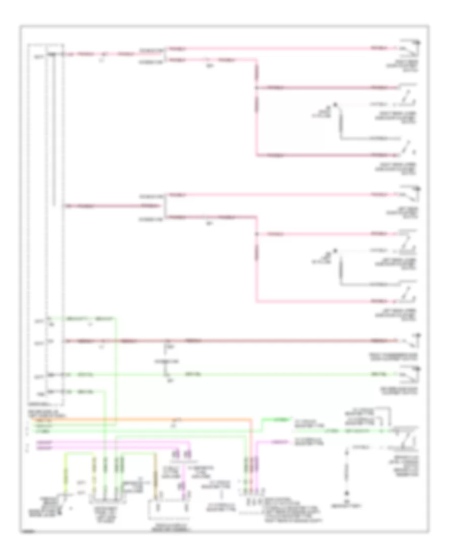
Instrument Cluster Wiring Diagram (2 of 2) for Toyota Tacoma X-Runner 2013
List of elements for Instrument Cluster Wiring Diagram (2 of 2) for Toyota Tacoma X-Runner 2013:
- (a/t)
- (m/t)
- Access cab
- Acty
- B16
- Be (left "b" pillar)
- Bf (right "c" pillar)
- Bf1
- Bg1
- Body ecu
- Brake fluid level warning switch (brake fluid reservoir)
- D11
- Dcty
- Double cab
- Driver side j/b (left side of dash)
- Driver's side door courtesy switch
- Eb (near battery)
- Front passenger's side door courtesy switch
- Ia1
- Ii1
- Il1
- Instrument panel j/b 1 (left side of dash)
- J15
- Lbl
- Left rear door courtesy switch
- Left rear lower side door courtesy switch
- Left rear upper side door courtesy switch
- Parking brake switch (base of park brake lever)
- Pcty
- Pkb
- R15
- R17
- Radio & display receiver assembly
- Rcty
- Right rear door courtesy switch
- Right rear lower side door courtesy switch
- Right rear upper side door courtesy switch
- Skid control ecu w/ actuator (hydraulic booster type: left rear of engine compt) (vacuum booster type: right rear of engine compt)
- Sp1
- Spd
- W/ built in type amplifier
- W/ hydraulic booster type
- W/ separate type amplifier
- W/ vacuum booster type
INTERIOR LIGHTS
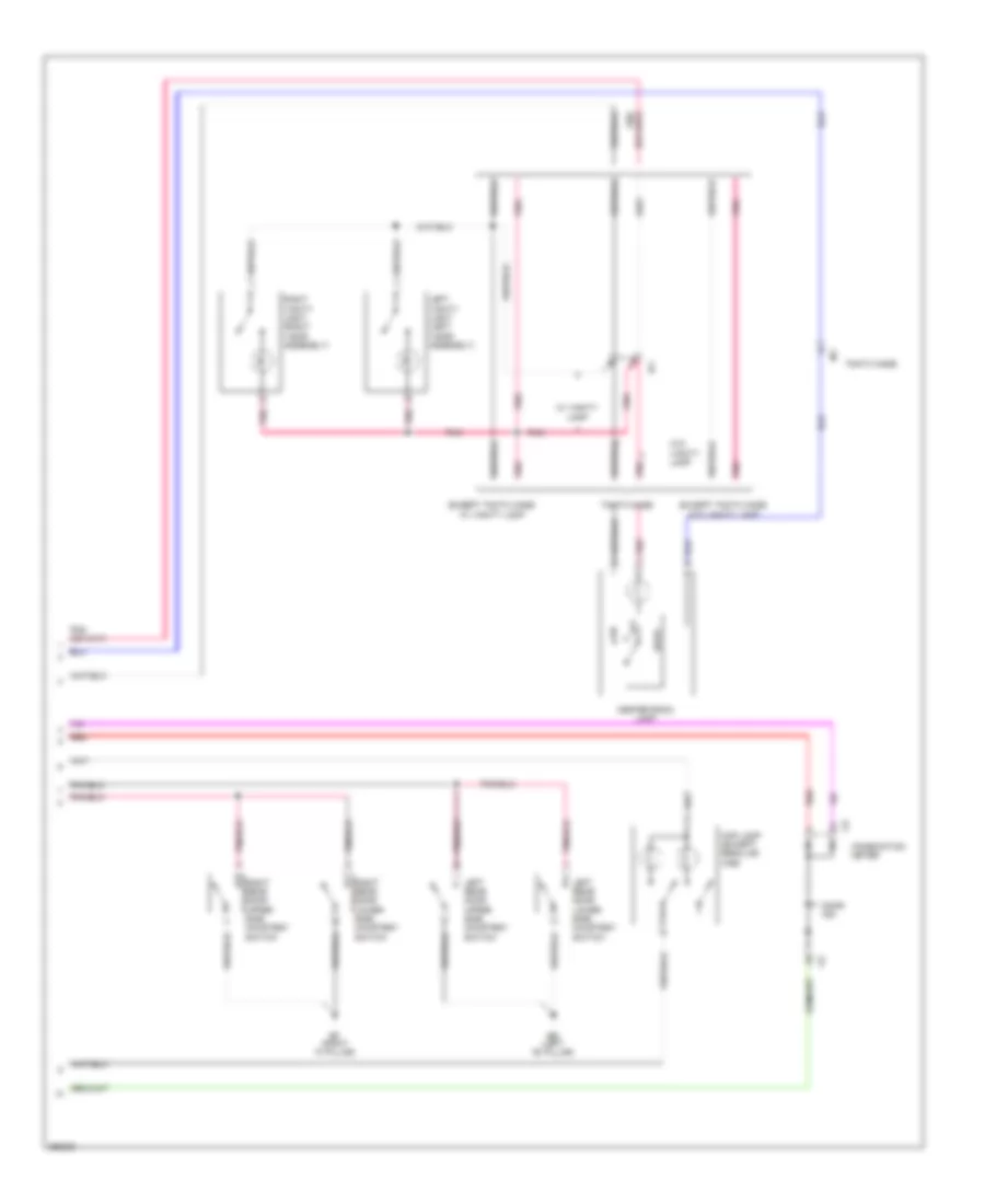
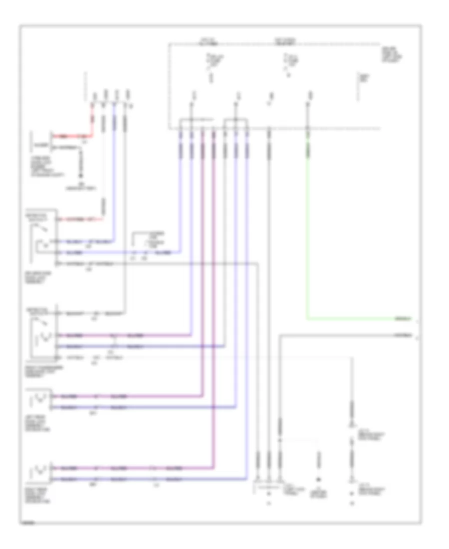
Courtesy Lamps Wiring Diagram (1 of 2) for Toyota Tacoma X-Runner 2013
List of elements for Courtesy Lamps Wiring Diagram (1 of 2) for Toyota Tacoma X-Runner 2013:
- (behind right kick panel) j/c 13
- (behind right kick panel) j/c 14
- Access cab
- Acty
- Altb
- Ba (under driver's seat)
- Bd (left rear frame rail)
- Be (left "b" pillar)
- Bf1
- Bg1
- Body ecu (driver side j/b)
- C16
- Dcty
- Dome fuse 7.5a
- Double cab
- Dr lck fuse 20a
- Driver side door lock assembly
- Driver side j/b (left side of dash)
- Driver's side door courtesy switch
- E11
- E12
- Ecu-b fuse 7.5a
- Ecub
- Engine room r/b 1 (left front of engine compt)
- Except tmmtx made
- F10
- F11
- Front passenger's side door courtesy switch
- Front passenger's side door lock assembly
- Gauge fuse 7.5a
- Gnd
- Ground distribution system
- H18
- Hot at all times
- Hot in on or start
- Ic (center of dash)
- Ic6
- Ig1 2 fuse 10a
- Ii1
- Ik3
- Il1
- Ile
- Ip1
- J/c 1 (left kick panel)
- J/c j4 & j5 (behind right side of dash)
- J15
- K13
- Left rear door courtesy switch
- Lswd
- Lswp
- O11
- O12
- Pcty
- Pnk
- Rcty
- Red
- Right rear door courtesy switch
- Switch detection
- Tmmtx made
- W/ door lock control
- W/o door lock control
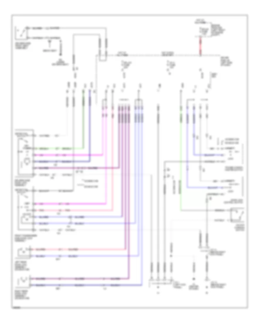
Courtesy Lamps Wiring Diagram (2 of 2) for Toyota Tacoma X-Runner 2013
List of elements for Courtesy Lamps Wiring Diagram (2 of 2) for Toyota Tacoma X-Runner 2013:
- Be (left "b" pillar)
- Bf (right "c" pillar)
- Center room lamp
- Combination meter
- Door
- Door ind
- Except tmmtx made w/ vanity lamp
- Except tmmtx made w/o vanity lamp
- Ip1
- Lamp
- Left rear door lower side courtesy switch
- Left rear door upper side courtesy switch
- Left vanity light (left visor assembly)
- Map lamp (except regular cab)
- Off
- Pnk
- Red
- Right rear door lower side courtesy switch
- Right rear door upper side courtesy switch
- Right vanity light (right visor assembly)
- Tmmtx made
- W/ vanity
- W/o vanity lamp
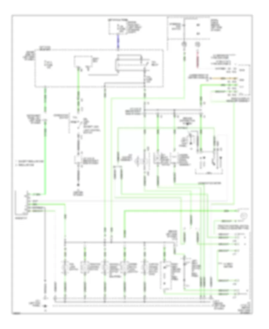
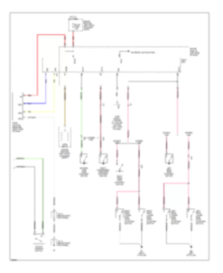
Instrument Illumination Wiring Diagram for Toyota Tacoma X-Runner 2013
List of elements for Instrument Illumination Wiring Diagram for Toyota Tacoma X-Runner 2013:
- (behind left side of dash) j/c 2
- (under front of center console) id
- A/c control assembly
- A/t shift lever illumi- nation
- A33
- Body ecu
- C11
- C13
- C14
- Combination meter
- Combination switch
- Cpu
- Curtain air bag cut off switch (4wd)
- Differ- ential lock switch
- Downhill assist control switch (if equipped)
- Driver side j/b (left side of dash)
- Drl (usa) off (except usa)
- Engine room r/b 1 (left front of engine compt)
- Except regular cab
- Fog lamp switch
- Gnd
- Ground distribution system
- Hazard warning signal switch assembly
- Head
- Hot at all times
- Hot in on or start
- Ic (center of dash)
- Ig1 2 fuse 10a
- Ij1
- Ill+
- Ill-
- Instrument panel j/b 1 (left side of dash)
- J/b fuse 50a
- J/c 1 (left kick panel)
- J/c 3 (behind left side of dash)
- J/c j17 & j16 (behind right side of dash)
- J/c j4 & j5 (behind right side of dash)
- J16
- J17
- J19
- Left seat heater switch (if equi- pped)
- Light control switch
- R15
- R16
- Radio & display receiver assembly
- Regular cab
- Rheostat
- Right seat heater switch (if equi- pped)
- Spiral cable (behind left side of dash)
- Steering pad switch
- Swg
- Tail
- Tail fuse 10a
- Tail relay
- Traction control switch
- Traction control switch (hydraulic booster type)
- Trly
- W/ built-in type amplifier
- W/ seat heater
- W/ separate type amplifier
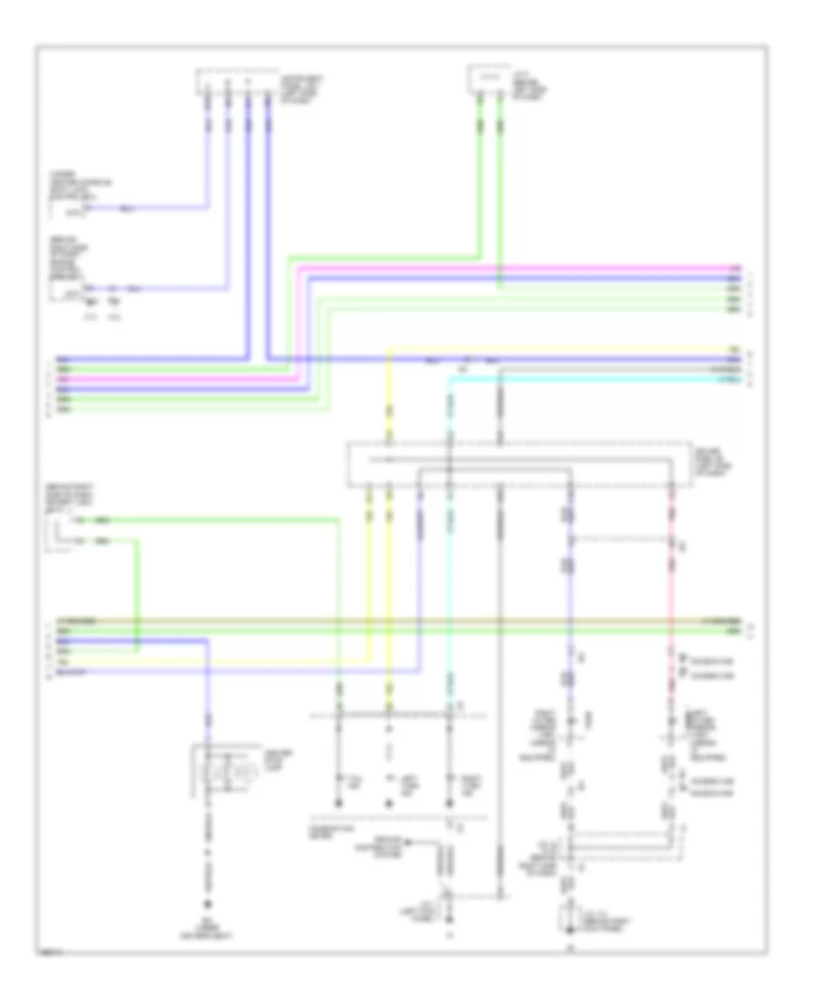
NAVIGATION
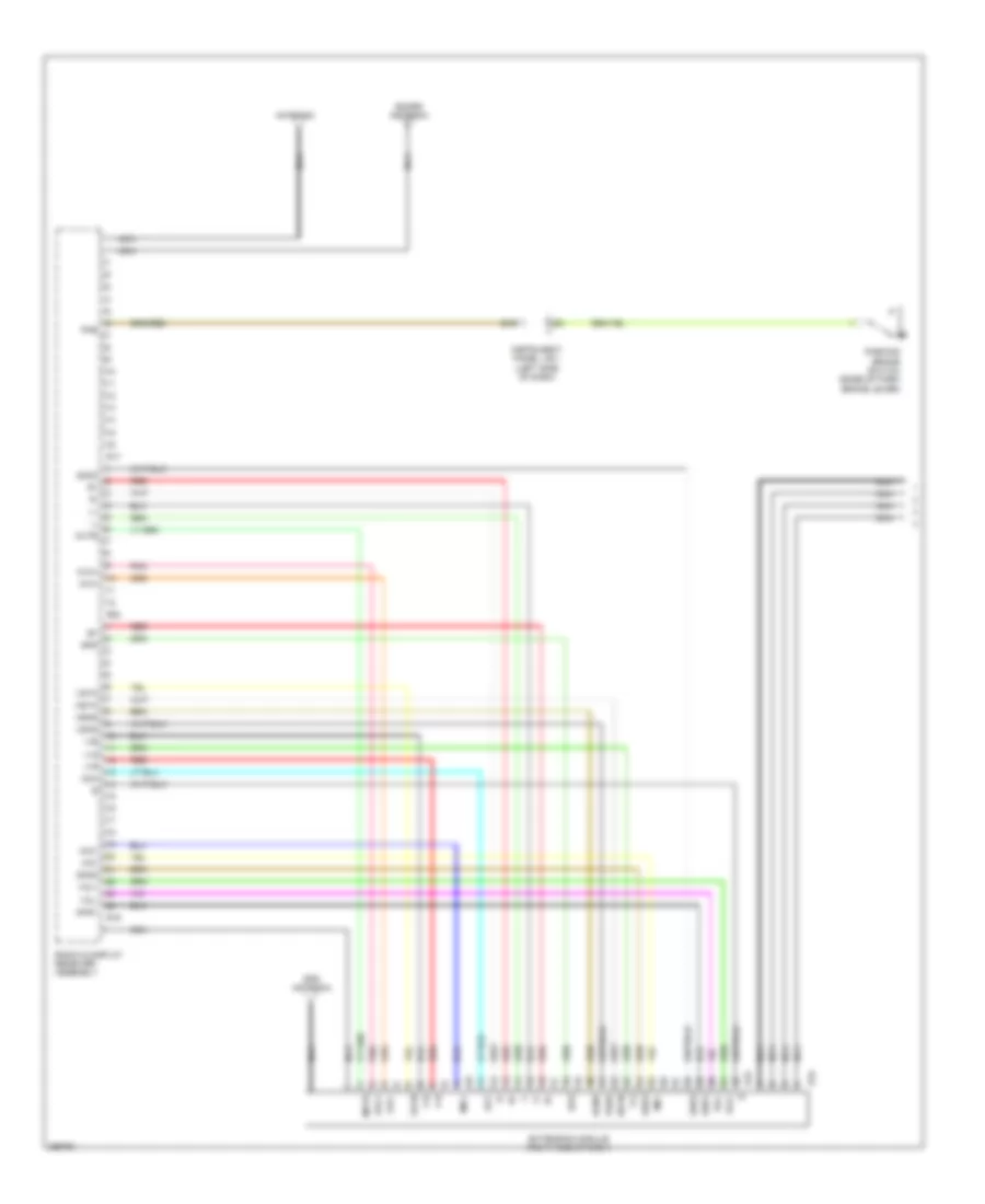
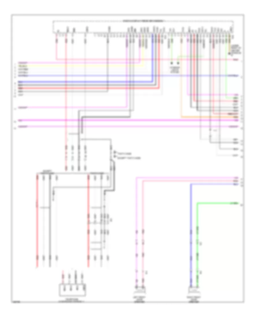
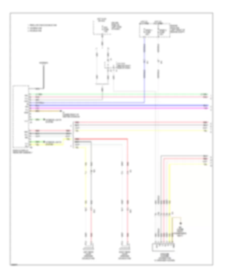
Navigation Wiring Diagram (1 of 4) for Toyota Tacoma X-Runner 2013
List of elements for Navigation Wiring Diagram (1 of 4) for Toyota Tacoma X-Runner 2013:
- Acc
- Agnd
- Antenna
- Avc+
- Avc-
- B16
- E15
- E16
- Extension module (right side of dash)
- Gps antenna
- Hsyn
- Instrument panel j/b 1 (left side of dash)
- Mic+
- Mic-
- Mute
- Nca
- Parking brake switch (base of park brake lever)
- Pkb
- Pnk
- R17
- R19
- R20
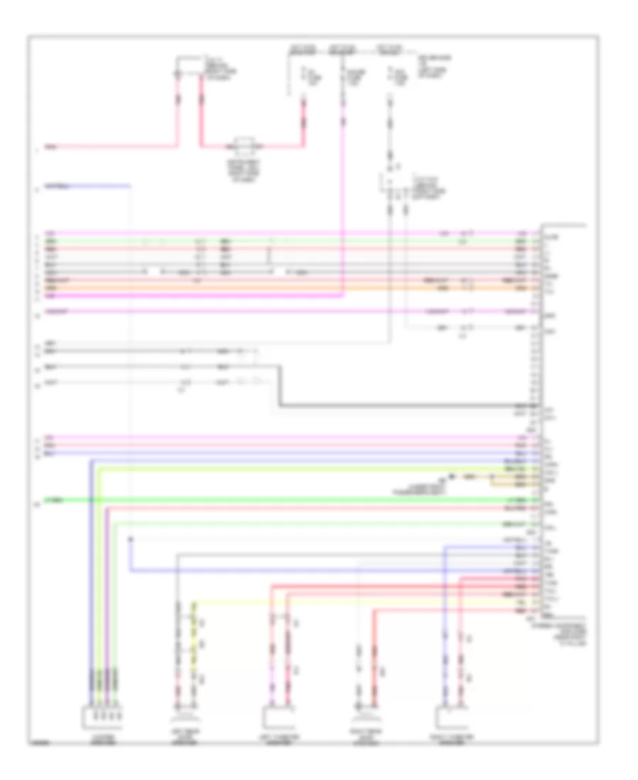
- Radio & display receiver assembly
- Red
- Sdars antenna
- Shd1
- Shd2
- Shd3
- Spd
- V-b
- V-g
- V-r
- Vol+
- Vol-
- Vshd
- Vsyn
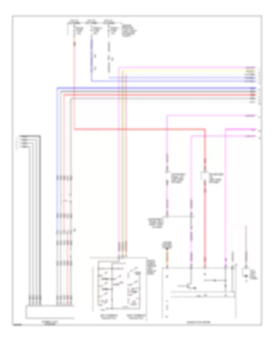
Navigation Wiring Diagram (2 of 4) for Toyota Tacoma X-Runner 2013
List of elements for Navigation Wiring Diagram (2 of 4) for Toyota Tacoma X-Runner 2013:
- A10
- B10
- C16
- Combination meter
- Cpu
- Cruise control system
- Driver side j/b (left side of dash)
- E13
- Ecu-b fuse 7.5a
- Engine room r/b (left front of engine compt)
- Hot at all times
- Ia1
- Ia4
- Il3
- Instrument panel j/b 1 (left side of dash)
- Instrument panel j/b 2 (right side of dash)
- Iq1
- J/c 1 (left kick panel)
- K13
- Left steering pad switch
- Mode
- Nca
- Off hook
- On hook
- Radio 1 fuse 10a
- Radio 2 fuse 30a
- Red
- Right steering pad switch
- Seek+
- Seek-
- Spiral cable (behind left side of dash)
- Stereo jack adapter
- Voice
- Vol+
- Vol-
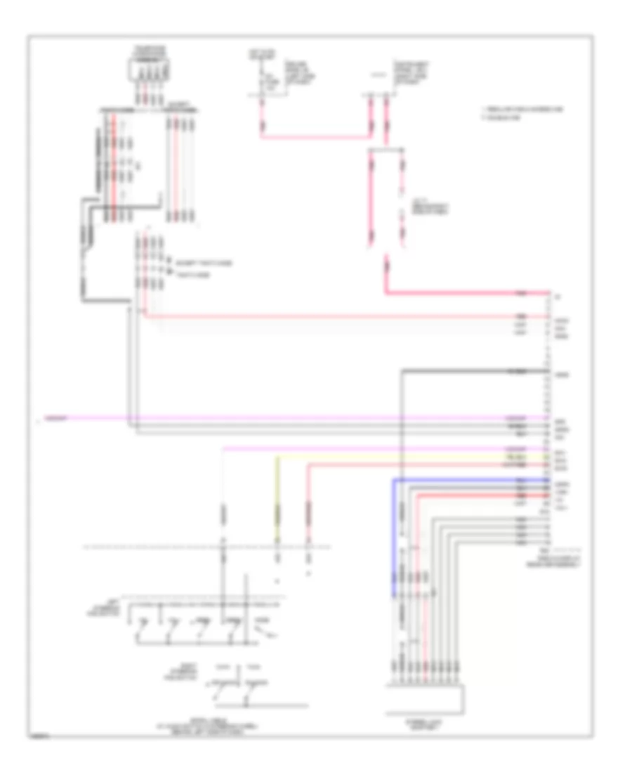
Navigation Wiring Diagram (3 of 4) for Toyota Tacoma X-Runner 2013
List of elements for Navigation Wiring Diagram (3 of 4) for Toyota Tacoma X-Runner 2013:
- (under front of center console) id
- +b1
- Acc1
- Adpg
- Agnd
- Except tmmtx made
- Gnd1
- Ic4
- Ik4
- Il3
- Ill+
- Ill-
- In1
- In2
- Interior lights system
- Ip2
- Ivo+
- Ivo-
- Left front door speaker
- Macc
- Mco+
- Mco-
- Min+
- Min-
- Mut1
- Nca
- Pnk
- R15
- R16
- Radio & display receiver assembly
- Red
- Right front door speaker
- Sgnd
- Sld
- Sld1
- Sns2
- Spd
- Sw1
- Sw2
- Swg
- Telephone microphone assembly
- Tmmtx made
- Tx2+
- Tx2-
- Va-
- Val+
- Var+
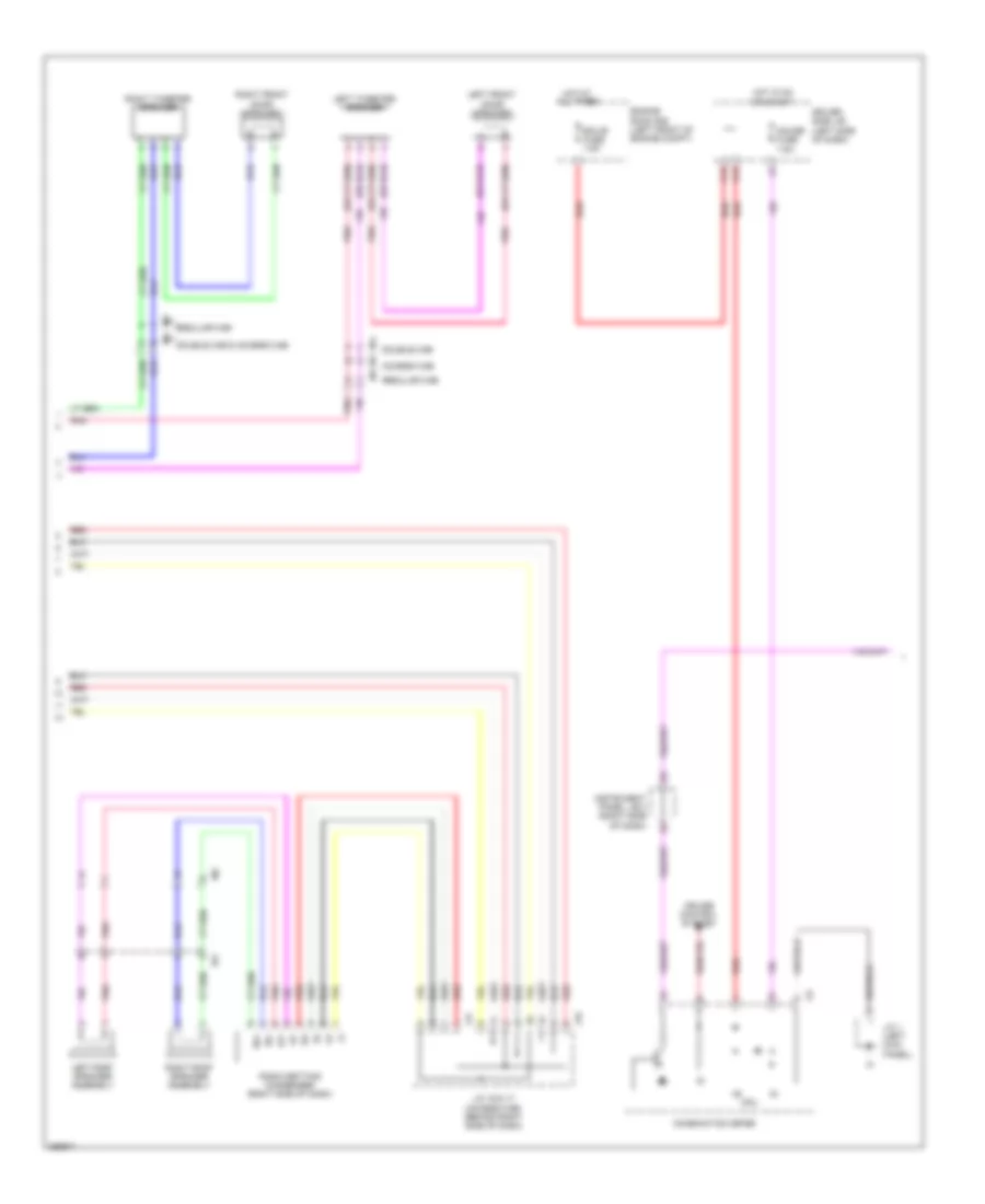
Navigation Wiring Diagram (4 of 4) for Toyota Tacoma X-Runner 2013
List of elements for Navigation Wiring Diagram (4 of 4) for Toyota Tacoma X-Runner 2013:
- +b2
- Acc
- Acc fuse 7.5a
- Ba1
- Bb (under front passenger's seat)
- Bb1
- Driver side j/b (left side of dash)
- Fl+
- Fl-
- Fr+
- Fr-
- Gauge fuse 7.5a
- Gnd
- Hot in on or acc
- Hot in on or start
- Ic4
- Ie2
- Ig1 fuse 10a
- Ik4
- Il3
- Il4
- Instrument panel j/b 2 (right side of dash)
- Int+
- Int-
- J/c 17 (behind right side of dash)
- J/c 4 & 5 (behind right side of dash)
- Left rear door speaker
- Left tweeter speaker
- Mute
- Nca
- Pnk
- Red
- Right rear door speaker
- Right tweeter speaker
- Rl+
- Rl-
- Rr+
- Rr-
- S23
- S24
- S31
- Sgnd
- Spd
- Stereo component amplifier (near right "c" pillar)
- Twl+
- Twl-
- Twr+
- Twr-
- Tx+
- Tx-
- Wf+
- Wf-
- Wfl+
- Wfl-
- Wfr+
- Wfr-
- Woofer speaker
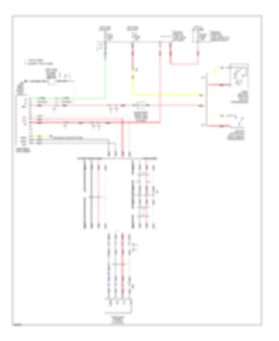
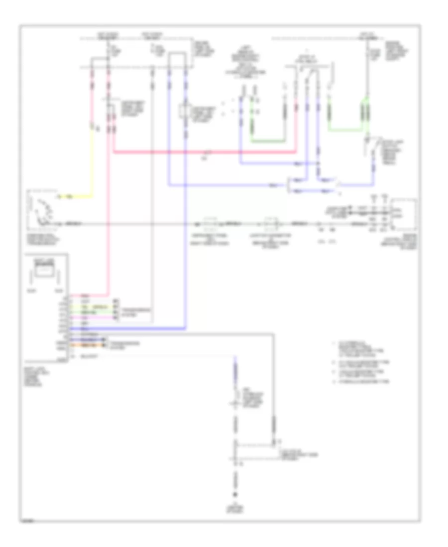
Rear View Camera Wiring Diagram for Toyota Tacoma X-Runner 2013
List of elements for Rear View Camera Wiring Diagram for Toyota Tacoma X-Runner 2013:
- (left side of dash) driver side j/b
- A/t
- Air conditioning system
- Backup lamp switch (right side of transmission)
- Bd (left rear frame rail)
- Bn1
- C16
- Cb+
- Cgnd
- Cv+
- Cv-
- Driver side j/b (left side of dash)
- E13
- Ecu-b fuse 7.5a
- Engine room r/b (left front of engine compt)
- Except tmmtx made
- H13
- Hot at all times
- Hot in on or start
- Ig1 2 fuse 10a
- Ig1 fuse 10a
- Ih1
- In1
- In2
- Inner rear view mirror
- Instrument panel j/b 2 (right side of dash)
- Io1
- Io2
- Ip1
- M/t
- Nca
- O13
- Park/ neutral position switch (transmission)
- Pnk
- Red
- Rev
- Television camera (tailgate)
- Temp
- Tmmtx made
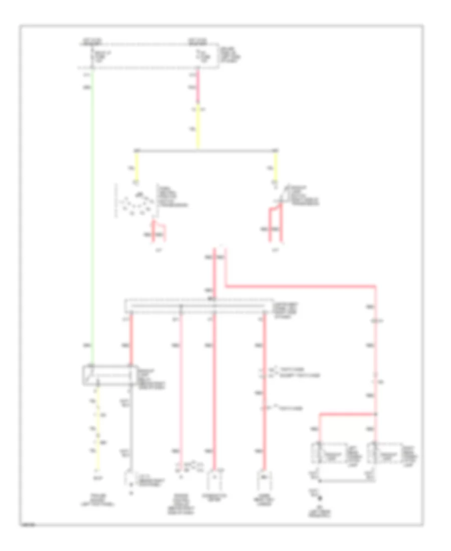
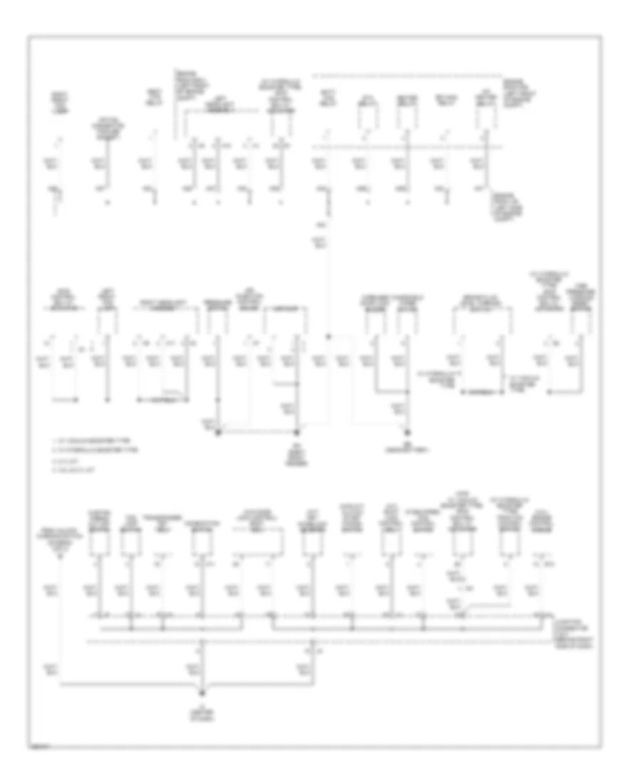
POWER DISTRIBUTION
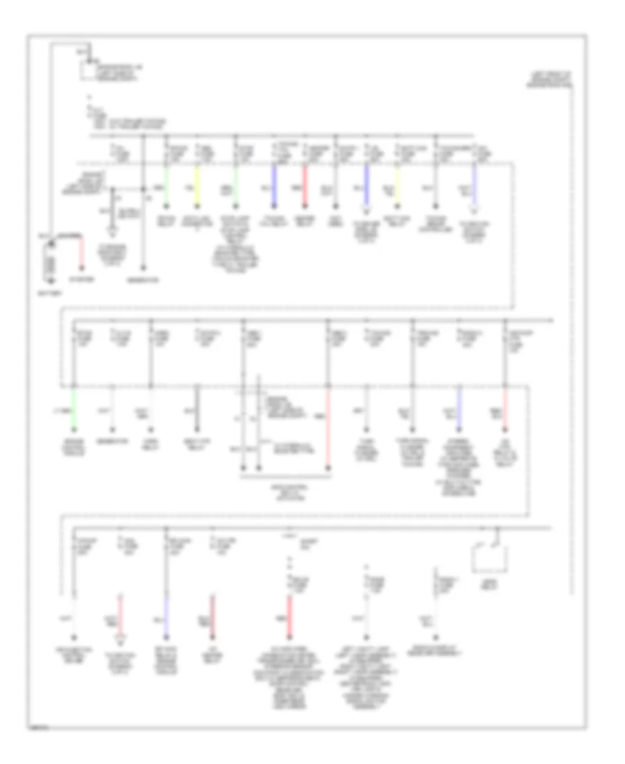
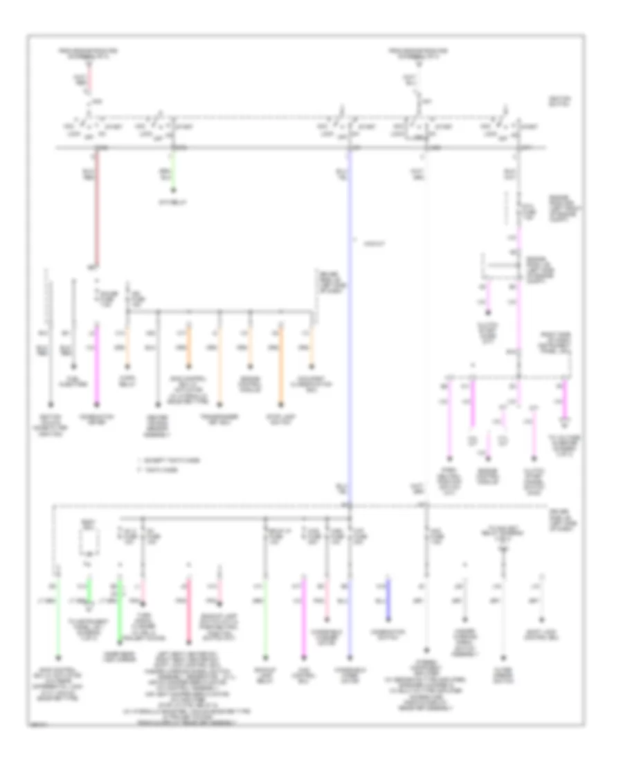
Power Distribution Wiring Diagram (1 of 3) for Toyota Tacoma X-Runner 2013
List of elements for Power Distribution Wiring Diagram (1 of 3) for Toyota Tacoma X-Runner 2013:
- (left front of engine compt) engine room r/b
- (not used)
- (w/o trailer towing) (w/ trailer towing)
- A/c amplifier, combination meter, transponder key ecu, steering sensor occupant classification ecu (w/ separate seat), door control receiver, body ecu & inner rear view mirror
- A/f heater relay
- A/f htr fuse 15a
- A/f htr relay & ai valve relay
- A/pump fuse 50a
- Abs 1 fuse 50a
- Abs 2 fuse 30a
- Air injection control driver
- Air pump htr fuse 10a
- Alt fuse 120a 140a
- Alt-s fuse 7.5a
- Am1 fuse 50a
- Am2 fuse 30a
- Batt chg fuse 30a
- Batt chg relay
- Battery
- Data link connector
- Dome fuse 7.5a
- Ecu-b fuse 7.5a
- Efi main fuse 20a
- Efi main relay & engine control module
- Engine control module
- Engine room j/b (left side of engine compt)
- Etcs fuse 10a
- Fr fog fuse 15a
- Fr fog relay
- Generator
- Head relay
- Heater fuse 50a
- Heater relay
- Horn fuse 10a
- Horn relay
- Inv fuse 100a
- J/b fuse 50a
- Left vanity light (left visor assembly) (if equipped) right vanity light (right visor assembly) (if equipped) center room lamp, map lamp & hazard warning signal switch assembly
- Obd fuse 7.5a
- Radio & display receiver assembly
- Radio 1 fuse 20a
- Radio 2 fuse 30a
- Red
- S/htr 1 fuse 50a
- S/htr 2 fuse 30a
- Seat htr relay
- Short pin
- Skid control ecu w/ actuator
- Starter
- Stereo component amplifier (w/ separate type amplifier) speaker (woofer) (w/ built-in type amplifier & access cab)
- Stop fuse 10a
- Stop lamp switch & stop lamp control relay (w/ hydraulic booster type, vacuum booster type w/ trailer towing)
- To driver side j/b (diagram 3 of 3)
- To engine room r/b 2 (diagram 3 of 3)
- To ignition switch (diagram 2 of 3)
- Towing brake controller
- Towing brk fuse 30a
- Towing fuse 30a
- Towing tail fuse 30a
- Towing tail relay
- Trn-haz fuse 15a
- Turn signal flasher (w/ drl & trailer towing)
- Turn signal flasher (w/ drl)
- W/ hydraulic booster type
Power Distribution Wiring Diagram (2 of 3) for Toyota Tacoma X-Runner 2013
List of elements for Power Distribution Wiring Diagram (2 of 3) for Toyota Tacoma X-Runner 2013:
- (2.7l)
- (right side of dash) instrument panel j/b 2
- 2.7l a/t
- 4.0l a/t
- 4wd control ecu
- 4wd fuse 20a
- 4wd m/t
- A/t
- A11
- Acc
- Acc fuse 7.5a
- Am1
- Am2
- B10
- B11
- B18
- Backup lamp relay
- Backup lamp switch (m/t) & park/neutral position switch (a/t)
- Bkup lp fuse 10a
- Body ecu
- C/opn relay
- C13
- C14
- C17
- Center air bag sensor assembly
- Clutch start cancel switch (4wd)
- Clutch start diode (m/t)
- Combination meter
- Combination switch
- Driver side j/b (left side of dash)
- Engine control module
- Engine room j/b (left side of engine compt)
- Engine room r/b (left front of engine compt)
- Except tmmtx made
- From engine room r/b (diagram 1 of 3)
- Fuel injectors
- Gauge fuse 7.5a
- H11
- H13
- H15
- H17
- H20
- Hazard warning signal switch assembly
- I13
- I15
- Ig1
- Ig1 2 fuse 10a
- Ig1 fuse 10a
- Ig2
- Ign fuse 15a
- Ignition coils & noise filter (ignition)
- Ignition switch
- Inner rear view mirror
- J10
- J16
- J20
- Left seat heater sw, right seat heater sw, shift lock control ecu, hazard warning signal switch assembly, generator, air mix damper servo motor, a/c control assembly, air vent damper servo motor, a/c amplifier, stop lp ctrl relay & (w/ hydraulic booster, vacuum booster type & trailer towing) radio & display receiver assembly
- Lock
- M/t
- Occupant classification ecu
- Off
- Outer mirror switch
- Park/ neutral position switch (a/t)
- Pnk
- Shift lock control ecu
- Skid control ecu w/ actuator (w/ hydraulic booster type)
- Skid control ecu w/ actuator (w/o rear differential lock & w/ vacuum booster type)
- St1
- St2
- Sta fuse 7.5a
- Sta relay
- Start
- Stereo component amplifier (w/ separate type amplifier), speaker (woofer) & (w/ built-in type amplifier access cab) radio & display receiver assembly
- Stop lamp switch
- Tmmtx made
- To acc skt relay (diagram 3 of 3)
- To instrument panel j/b 1 (diagram 3 of 3)
- To voltage inverter (diagram 3 of 3)
- Transponder key ecu
- Turn signal flasher (w/ drl & trailer towing)
- Windshield washer motor
- Windshield wiper motor
- Wip fuse 30a
- Wsh fuse 10a
Power Distribution Wiring Diagram (3 of 3) for Toyota Tacoma X-Runner 2013
List of elements for Power Distribution Wiring Diagram (3 of 3) for Toyota Tacoma X-Runner 2013:
- (2.7l)
- (4.0l)
- (a/t)
- (m/t)
- 400w
- A11
- A12
- A13
- Ac skt relay
- Ac1
- Ac2
- Acc skt relay
- Acc1
- Acc2
- Altb
- B15
- Batt chg relay (w/ trailer towing)
- Bc (under front passenger's seat)
- Bc1
- Bc2
- Body ecu
- C11
- C13
- C14
- Cccl
- Clutch start cancel switch (4wd m/t)
- Combination meter, engine control module, (2.7l) hazard warning signal switch assembly & tail diode (4.0l)
- Cruise control clutch switch (m/t)
- Cruise control system
- D10
- Differential lock switch
- Dr lck fuse 20a
- Driver side j/b (left side of dash)
- E13
- E21
- Ed1
- Ed2
- Els2
- Els3
- Engine control module
- Engine room r/b 2 (left front of engine compt)
- From acc fuse (diagram 2 of 3)
- From driver side j/b (diagram 2 of 3)
- From engine room j/b (diagram 1 of 3)
- From engine room r/b (diagram 1 of 3)
- From instrument panel j/b 2 (diagram 2 of 3)
- Front power outlet socket 2 power point socket assembly (12v)
- Front power point socket 1 power point socket assembly (12v)
- Generator (4.0l)
- Gnd
- H18
- Heater relay
- Ia4
- Im1
- Ind
- Instrument cluster system
- Instrument panel j/b 1 (left side of dash)
- J19
- Junction connector j1 (left kick panel)
- K11
- Left headlight assembly
- Left rear combination lamp, right rear combination lamp, left license plate lamp & right license plate lamp
- Left seat heater switch, right seat heater switch, spiral cable, rheostat, fog lamp switch, traction control switch, downhill assist control switch, (if equipped) differential lock switch, towing brake connector & curtain air bag cutoff switch (4wd)
- Mg clt relay
- Nsw
- Out
- P/t
- P/w relay
- Pgnd
- Power ind+ outlet main switch (120v) ind-
- Pwr outlet fuse 15a
- Rear power point socket assembly (120v)
- Red
- Redr
- Rheostat
- Right headlight assembly
- Seat heater relay
- Skid control ecu w/ actuator
- Spd
- Steering sensor
- Tail fuse 10a
- Tail relay
- Tire pressure warning ecu
- Towing tail relay
- Trly
- Voltage inverter (under front passenger's seat)
- W/ trailer towing
- W/o trailer towing
- Yaw rate sensor
POWER DOOR LOCKS
Power Door Locks Wiring Diagram, with Keyless Entry (1 of 2) for Toyota Tacoma X-Runner 2013
List of elements for Power Door Locks Wiring Diagram, with Keyless Entry (1 of 2) for Toyota Tacoma X-Runner 2013:
- Access cab
- Act+
- Act-
- Actd
- Altb
- Ba1
- Bb1
- Body ecu
- Buzzer
- Bzr
- Detection switch
- Double cab
- Dr lck fuse 20a
- Driver side j/b (left side of dash)
- Driver's side door lock assembly
- Eb (near battery)
- Front passenger's side door lock assembly
- Gnd
- H18
- H22
- H23
- H24
- Hot at all times
- Hot in run or start
- Ia1
- Ic (center of dash)
- Ic1
- Ic6
- Ig1 2 fuse 10a
- Ik3
- Ik4
- Il2
- J/c 1 (left kick panel)
- J/c 13 (behind right kick panel)
- J/c 14 (behind right kick panel)
- K10
- Ksw
- Left rear door lock assembly (double cab)
- Lswd
- Lswp
- Red
- Right rear door lock assembly (double cab)
- Wireless door lock buzzer (left front of engine compt)
Power Door Locks Wiring Diagram, with Keyless Entry (2 of 2) for Toyota Tacoma X-Runner 2013
List of elements for Power Door Locks Wiring Diagram, with Keyless Entry (2 of 2) for Toyota Tacoma X-Runner 2013:
- Access cab
- Be (left "b" pillar)
- Bf (right "c" pillar)
- Bf1
- Bg1
- Body ecu
- C10
- C16
- Dcty
- Door control receiver (right side of dash)
- Double cab
- Driver side j/b (left side of dash)
- Driver's side door courtesy switch
- Ecu-b fuse 7.5a
- Ecub
- Engine room r/b (left front of engine compt)
- Exterior lights system
- Front passenger's side door courtesy switch
- Gnd
- Haz
- Horn
- Horn relay
- Hot at all times
- I16
- Il1
- J/c 13 (behind right kick panel)
- J/c 14 (behind right kick panel)
- J15
- Left rear door courtesy switch
- Left rear lower side door courtesy switch
- Left rear upper side door courtesy switch
- Pcty
- Prg
- Rcty
- Rda
- Red
- Right rear door courtesy switch
- Right rear lower side door courtesy switch
- Right rear upper side door courtesy switch
- Trly
- Turn signal flasher (w/ trailer towing) (left side of dash)
- Unlock warning switch
Power Door Locks Wiring Diagram, without Keyless Entry for Toyota Tacoma X-Runner 2013
List of elements for Power Door Locks Wiring Diagram, without Keyless Entry for Toyota Tacoma X-Runner 2013:
- Access cab
- Act+
- Act-
- Actd
- Altb
- Ba (under driver's seat)
- Ba1
- Bb1
- Bench seat
- Bi2
- Body ecu
- C16
- Dbkl
- Detection switch
- Door lock control switch
- Double cab
- Dr lck fuse 20a
- Driver side j/b (left side of dash)
- Driver's side door lock assembly
- Driver's side front seat inner belt
- Ecu-b fuse 7.5a
- Ecub
- Engine room r/b (left front of engine compt)
- Front passenger's side door lock assembly
- Gnd
- H18
- H22
- H23
- H24
- Hot at all times
- Hot in run or start
- I14
- I17
- I18
- I19
- Ic (center of dash)
- Ic1
- Ic6
- Ic7
- Ig1 2 fuse 10a
- Ik3
- Ik4
- Il2
- J/c 1 (left kick panel)
- J/c 13 (behind right kick panel)
- J/c 14 (behind right kick panel)
- J13
- K10
- Key unlock
- Ksw
- Left rear door lock assembly (double cab)
- Lock
- Lswd
- Lswp
- Pnk
- Power window master switch
- Red
- Right rear door lock assembly (double cab)
- Ul1
- Ul2
- Ul3
- Unlock
- Unlock warning switch
POWER MIRRORS
Electrochromic Mirror Wiring Diagram for Toyota Tacoma X-Runner 2013
List of elements for Electrochromic Mirror Wiring Diagram for Toyota Tacoma X-Runner 2013:
- (left side of dash) driver side j/b
- A/t
- Air conditioning system
- Backup lamp switch (right side of transmission)
- Bd (left rear frame rail)
- Bn1
- C16
- Cb+
- Cgnd
- Cv+
- Cv-
- Driver side j/b (left side of dash)
- E13
- Ecu-b fuse 7.5a
- Engine room r/b (left front of engine compt)
- Except tmmtx made
- H13
- Hot at all times
- Hot in on or start
- Ig1 2 fuse 10a
- Ig1 fuse 10a
- Ih1
- In1
- In2
- Inner rear view mirror
- Instrument panel j/b 2 (right side of dash)
- Io1
- Io2
- Ip1
- M/t
- Nca
- O13
- Park/ neutral position switch (transmission)
- Pnk
- Red
- Rev
- Television camera (tailgate)
- Temp
- Tmmtx made
Power Mirrors Wiring Diagram for Toyota Tacoma X-Runner 2013
List of elements for Power Mirrors Wiring Diagram for Toyota Tacoma X-Runner 2013:
- Acc fuse 7.5a
- Down
- Driver side j/b (left side of dash)
- Exterior lights
- F11
- Hot in run or acc
- Ic6
- Ik3
- Instrument panel j/b 2 (right side of dash)
- J/c 1 (left kick panel)
- J16
- Left
- Left outer rear view mirror
- Mlh
- Mlv
- Mrh
- Mrv
- Operation switch
- Outer mirror switch
- Pnk
- Right
- Right outer rear view mirror
- Select switch
- System
- Turn
POWER SEATS
Power Seats Wiring Diagram for Toyota Tacoma X-Runner 2013
List of elements for Power Seats Wiring Diagram for Toyota Tacoma X-Runner 2013:
- A32
- A33
- Ba (under driver's seat)
- Bb (under front passenger's seat)
- C13
- C14
- Driver side j/b (left side of dash)
- Ea (right front fender)
- Engine room j/b (left side of engine compt)
- Engine room r/b (left front of engine compt)
- Engine room r/b 2 (left front of engine compt)
- Hot at all times
- Hot in on or start
- Ia4
- Ie2
- Ig1 2 fuse 10a
- Ig1 fuse 10a
- Il1
- Ill+
- Ill-
- Instrument panel j/b 1 (left side of dash)
- Instrument panel j/b 2 (right side of dash)
- Interior lights system
- J/c (behind right kick panel)
- J/c 16 & 17 (behind right side of dash)
- J/c 16 & 17 (behind right side of dash) j16
- J/c 5 (behind right side of dash)
- J16
- J17
- Left front seat cushion heater assembly
- Left seat heater switch
- Pnk
- Right front seat cushion heater assembly
- Right seat heater switch
- S/htr 2 fuse 30a
- Seat back heater
- Seat cushion heater
- Seat heater control
- Seat htr relay
- Thl
- Thr
POWER WINDOWS
Power Windows Wiring Diagram for Toyota Tacoma X-Runner 2013
List of elements for Power Windows Wiring Diagram for Toyota Tacoma X-Runner 2013:
- Access cab
- Altb
- Auto down
- Ba1
- Bb1
- Bf1
- Bg1
- Body ecu
- C16
- D fr p/w fuse 30a
- D rr p/w fuse 20a
- Dcty
- Door locks system
- Double cab
- Down
- Dr lck fuse 20a
- Driver side j/b (left side of dash)
- Driver's side door courtesy switch
- Ecu-b fuse 7.5a
- Ecub
- Engine room r/b (left front of engine compt)
- F17
- Front passenger
- Front passenger's side door courtesy switch
- Front passenger's side power window switch
- Gnd
- H14
- H16
- H18
- Hot at all times
- Hot in run or start
- Ic1
- Ic4
- Ic7
- Ie2
- Ig1 2 fuse 10a
- Ik4
- Il1
- Il2
- J/b fuse 50a
- J/c 1 (left kick panel)
- Left front power window regulator motor
- Left rear
- Left rear power window regulator motor (double cab)
- Left rear power window switch (double cab)
- Lock
- P fr p/w fuse 20a
- P rr p/w fuse 20a
- P/w relay
- Pcty
- Power window master switch
- Pws
- Red
- Right front power window regulator motor
- Right rear
- Right rear power window regulator motor (double cab)
- Right rear power window switch (double cab)
- Unlock
- Window lock switch
RADIO
Radio Wiring Diagram, with Navigation (1 of 4) for Toyota Tacoma X-Runner 2013
List of elements for Radio Wiring Diagram, with Navigation (1 of 4) for Toyota Tacoma X-Runner 2013:
- Acc
- Agnd
- Antenna
- Avc+
- Avc-
- B16
- E15
- E16
- Extension module (right side of dash)
- Gps antenna
- Hsyn
- Instrument panel j/b 1 (left side of dash)
- Mic+
- Mic-
- Mute
- Nca
- Parking brake switch (base of park brake lever)
- Pkb
- Pnk
- R17
- R19
- R20
- Radio & display receiver assembly
- Red
- Sdars antenna
- Shd1
- Shd2
- Shd3
- Spd
- V-b
- V-g
- V-r
- Vol+
- Vol-
- Vshd
- Vsyn
Radio Wiring Diagram, with Navigation (2 of 4) for Toyota Tacoma X-Runner 2013
List of elements for Radio Wiring Diagram, with Navigation (2 of 4) for Toyota Tacoma X-Runner 2013:
- A10
- B10
- C16
- Combination meter
- Cpu
- Cruise control system
- Driver side j/b (left side of dash)
- E13
- Ecu-b fuse 7.5a
- Engine room r/b (left front of engine compt)
- Hot at all times
- Ia1
- Ia4
- Il3
- Instrument panel j/b 1 (left side of dash)
- Instrument panel j/b 2 (right side of dash)
- Iq1
- J/c 1 (left kick panel)
- K13
- Left steering pad switch
- Mode
- Nca
- Off hook
- On hook
- Radio 1 fuse 10a
- Radio 2 fuse 30a
- Red
- Right steering pad switch
- Seek+
- Seek-
- Spiral cable (behind left side of dash)
- Stereo jack adapter
- Voice
- Vol+
- Vol-
Radio Wiring Diagram, with Navigation (3 of 4) for Toyota Tacoma X-Runner 2013
List of elements for Radio Wiring Diagram, with Navigation (3 of 4) for Toyota Tacoma X-Runner 2013:
- (under front of center console) id
- +b1
- Acc1
- Adpg
- Agnd
- Except tmmtx made
- Gnd1
- Ic4
- Ik4
- Il3
- Ill+
- Ill-
- In1
- In2
- Interior lights system
- Ip2
- Ivo+
- Ivo-
- Left front door speaker
- Macc
- Mco+
- Mco-
- Min+
- Min-
- Mut1
- Nca
- Pnk
- R15
- R16
- Radio & display receiver assembly
- Red
- Right front door speaker
- Sgnd
- Sld
- Sld1
- Sns2
- Spd
- Sw1
- Sw2
- Swg
- Telephone microphone assembly
- Tmmtx made
- Tx2+
- Tx2-
- Va-
- Val+
- Var+
Radio Wiring Diagram, with Navigation (4 of 4) for Toyota Tacoma X-Runner 2013
List of elements for Radio Wiring Diagram, with Navigation (4 of 4) for Toyota Tacoma X-Runner 2013:
- +b2
- Acc
- Acc fuse 7.5a
- Ba1
- Bb (under front passenger's seat)
- Bb1
- Driver side j/b (left side of dash)
- Fl+
- Fl-
- Fr+
- Fr-
- Gauge fuse 7.5a
- Gnd
- Hot in on or acc
- Hot in on or start
- Ic4
- Ie2
- Ig1 fuse 10a
- Ik4
- Il3
- Il4
- Instrument panel j/b 2 (right side of dash)
- Int+
- Int-
- J/c 17 (behind right side of dash)
- J/c 4 & 5 (behind right side of dash)
- Left rear door speaker
- Left tweeter speaker
- Mute
- Nca
- Pnk
- Red
- Right rear door speaker
- Right tweeter speaker
- Rl+
- Rl-
- Rr+
- Rr-
- S23
- S24
- S31
- Sgnd
- Spd
- Stereo component amplifier (near right "c" pillar)
- Twl+
- Twl-
- Twr+
- Twr-
- Tx+
- Tx-
- Wf+
- Wf-
- Wfl+
- Wfl-
- Wfr+
- Wfr-
- Woofer speaker
Radio Wiring Diagram, without Navigation (1 of 3) for Toyota Tacoma X-Runner 2013
List of elements for Radio Wiring Diagram, without Navigation (1 of 3) for Toyota Tacoma X-Runner 2013:
- Acc
- Acc fuse 7.5a
- Access cab
- Antenna
- Ba1
- Bb (under front passenger's seat)
- Bb1
- Double cab
- Driver side j/b (left side of dash)
- Engine room r/b (left front of engine compt)
- Fl+
- Fl-
- Fr+
- Fr-
- Gnd
- Hot at all times
- Hot in on or acc
- Ia1
- Ia4
- Id (under front of center console)
- Ie2
- Il2
- Il4
- Ill+
- Ill-
- Interior lights system
- J/c 4 & 5 (behind right side of dash)
- Left rear door speaker (double cab)
- Nca
- Pnk
- Radio & display receiver assembly
- Radio 1 fuse 20a
- Radio 2 fuse 30a
- Red
- Regular cab & double cab
- Right rear door speaker (double cab)
- Rl+
- Rl-
- Rr+
- Rr-
- Speaker (woofer) (access cab w/ speaker woofer)
Radio Wiring Diagram, without Navigation (2 of 3) for Toyota Tacoma X-Runner 2013
List of elements for Radio Wiring Diagram, without Navigation (2 of 3) for Toyota Tacoma X-Runner 2013:
- Access cab
- C16
- Combination meter
- Cpu
- Cruise control system
- Double cab
- Double cab & access cab
- Driver side j/b (left side of dash)
- Ecu-b fuse 7.5a
- Engine room r/b (left front of engine compt)
- Gauge fuse 7.5a
- Hot at all times
- Hot in on or start
- Ic1
- Ic2
- Ic4
- Ik2
- Ik4
- In2
- Instrument panel j/b 2 (right side of dash)
- Ip2
- J/c 1 (left kick panel)
- J/c 16 & 17 (access cab) (behind right side of dash)
- J16
- J17
- K13
- Left front door speaker
- Left roof speaker assembly
- Left tweeter speaker
- Li+
- Li-
- Lo+
- Lo-
- Pnk
- Radio setting condenser (right side of dash)
- Red
- Regular cab
- Ri+
- Ri-
- Right front door speaker
- Right roof speaker assembly
- Right tweeter speaker
- Ro+
- Ro-
Radio Wiring Diagram, without Navigation (3 of 3) for Toyota Tacoma X-Runner 2013
List of elements for Radio Wiring Diagram, without Navigation (3 of 3) for Toyota Tacoma X-Runner 2013:
- Adpg
- Agnd
- Au1
- Au2
- Double cab
- Driver side j/b (left side of dash)
- Eau
- Except tmmtx made
- Hot in on or start
- Ig1 fuse 10a
- In1
- In2
- Instrument panel j/b 2 (right side of dash)
- Ip2
- Iq1
- J/c 17 (behind right side of dash)
- Left steering pad switch
- Macc
- Mco+
- Mco-
- Min+
- Min-
- Mode
- Nca
- Off hook
- On hook
- Pnk
- R15
- R22
- Radio & display receiver assembly
- Red
- Regular cab & access cab
- Right steering pad switch
- Seek+
- Seek-
- Sgnd
- Shield
- Sns2
- Spd
- Spiral cable (w/ audio switch in steering wheel) (behind left side of dash)
- Stereo jack adapter 1
- Sw1
- Sw2
- Swg
- Telephone microphone assembly
- Tmmtx made
- Va-
- Val+
- Var+
- Vol+
- Vol-
SHIFT INTERLOCK
Shift Interlock Wiring Diagram for Toyota Tacoma X-Runner 2013
List of elements for Shift Interlock Wiring Diagram for Toyota Tacoma X-Runner 2013:
- (left rear of engine compt) skid control ecu w/ actuator (hydraulic booster type)
- 2.7l
- 4.0l
- Acc
- Acc fuse 7.5a
- At2
- At3
- Atd
- Atl
- B13
- Canh
- Canl
- Computer data lines system
- Driver side j/b (left side of dash)
- E10
- E14
- E19
- E22
- Engine control module (behind right side of dash)
- Engine room r/b (left front of engine compt)
- H13
- Hot at all times
- Hot in run or acc
- Hot in run or start
- Hydraulic booster type
- Ia3
- Ic (center of dash)
- Ig1 fuse 10a
- Ih1
- Ih2
- Instrument panel j/b 1 (left side of dash)
- Instrument panel j/b 2 (right side of dash)
- J/c j4 & j5 (behind right side of dash)
- J10
- Junction connector j5 (behind right side of dash)
- Key interlock solenoid (left side of dash)
- Kls+
- Nssd
- Nssl
- Park/neutral position switch (transmission)
- Pnk
- Shift lock control ecu (under center console)
- Shift lock solenoid
- Sls+
- Sls-
- Stop fuse 10a
- Stop lamp switch (bracket, above brake pedal)
- Stop lp ctrl relay
- Stp
- Stp2
- Stpo
- System
- Transmissions
- Vacuum booster type w/ trailer towing
- W/ hydraulic booster type & vacuum booster type w/ trailer towing
- W/ vacuum booster type w/o trailer towing
STARTING/CHARGING
2.7L
2.7L, Charging Wiring Diagram for Toyota Tacoma X-Runner 2013
List of elements for 2.7L, Charging Wiring Diagram for Toyota Tacoma X-Runner 2013:
- (behind right side of dash) engine control module
- A15
- Alt
- Alt fuse 120a
- Alt-s fuse 7.5a
- B12
- Battery
- Body ecu (driver side j/b)
- Charge ind
- Combination meter
- Driver side j/b (left side of dash)
- E17
- Ea1
- Engine room j/b (left side of engine compt)
- Engine room r/b (left front of engine compt)
- Gauge fuse 7.5a
- Generator
- Hot in run or start
- Ig1 fuse 10a
- Ih1
- Instrument panel j/b 1 (left side of dash)
- Instrument panel j/b 2 (right side of dash)
- Pnk
- Starting circuit
2.7L, Starting Wiring Diagram for Toyota Tacoma X-Runner 2013
List of elements for 2.7L, Starting Wiring Diagram for Toyota Tacoma X-Runner 2013:
- (2.7l)
- (4.0l)
- 2.7l a/t
- 4.0l a/t
- 4wd m/t
- A/t
- A11
- A26
- A33
- Acc
- Alt fuse 120a
- Am1
- Am1 fuse 50a
- Am2
- Am2 fuse 30a
- B15
- B18
- Battery
- C13
- C14
- Clutch start cancel switch (4wd m/t) (bracket above clutch pedal)
- Clutch start diode (m/t) (left side of dash)
- Clutch start switch (m/t) (bracket above clutch pedal)
- D16
- Driver side j/b (left side of dash)
- E10
- E14
- E22
- Ea (right front fender)
- Eb1
- Engine control module (behind right side of dash)
- Engine room j/b (left side of engine compt)
- Engine room r/b (left front of engine compt)
- Hot in run or start
- Ic (center of dash)
- Ig1 2 fuse 10a
- Ignition switch
- Ih1
- Instrument panel j/b 1 (left side of dash)
- Instrument panel j/b 2 (right side of dash)
- J/c j4 & j5 (behind right side of dash)
- Lock
- Nsw
- On off
- Park/ neutral position switch (trans- mission)
- Solid state
- Sta
- Sta fuse 7.5a
- Sta relay
- Start st1
- Start st2
- Starter
4.0L
4.0L, Charging Wiring Diagram for Toyota Tacoma X-Runner 2013
List of elements for 4.0L, Charging Wiring Diagram for Toyota Tacoma X-Runner 2013:
- Alt fuse 120a
- Alt-s fuse 7.5a
- B12
- Battery
- Body ecu (driver side j/b)
- C13
- C14
- Charge ind
- Combination meter
- Driver side j/b (left side of dash)
- Eb1
- Engine room j/b (left side of engine compt)
- Engine room r/b (left front of engine compt)
- Gauge fuse 7.5a
- Generator
- Hot in run or start
- Ig1 2 fuse 10a
- Instrument panel j/b 1 (left side of dash)
- Starting circuit
4.0L, Starting Wiring Diagram for Toyota Tacoma X-Runner 2013
List of elements for 4.0L, Starting Wiring Diagram for Toyota Tacoma X-Runner 2013:
- (2.7l)
- (4.0l)
- 2.7l a/t
- 4.0l a/t
- 4wd m/t
- A/t
- A11
- A26
- A33
- Acc
- Alt fuse 120a
- Am1
- Am1 fuse 50a
- Am2
- Am2 fuse 30a
- B15
- B18
- Battery
- C13
- C14
- Clutch start cancel switch (4wd m/t) (bracket above clutch pedal)
- Clutch start diode (m/t) (left side of dash)
- Clutch start switch (m/t) (bracket above clutch pedal)
- D16
- Driver side j/b (left side of dash)
- E10
- E14
- E22
- Ea (right front fender)
- Eb1
- Engine control module (behind right side of dash)
- Engine room j/b (left side of engine compt)
- Engine room r/b (left front of engine compt)
- Hot in run or start
- Ic (center of dash)
- Ig1 2 fuse 10a
- Ignition switch
- Ih1
- Instrument panel j/b 1 (left side of dash)
- Instrument panel j/b 2 (right side of dash)
- J/c j4 & j5 (behind right side of dash)
- Lock
- Nsw
- On off
- Park/ neutral position switch (trans- mission)
- Solid state
- Sta
- Sta fuse 7.5a
- Sta relay
- Start st1
- Start st2
- Starter
SUPPLEMENTAL RESTRAINTS
Supplemental Restraints Wiring Diagram, Bench Seat (1 of 2) for Toyota Tacoma X-Runner 2013
List of elements for Supplemental Restraints Wiring Diagram, Bench Seat (1 of 2) for Toyota Tacoma X-Runner 2013:
- (base of right "b" pillar) right front side air bag sensor
- (behind right side of dash) air bag squib (front passenger's air bag assembly)
- (right "b" pillar) right curtain shield air bag squib
- (under steering wheel pad) air bag squib (steering wheel pad)
- +sl
- +sr
- -sl
- -sr
- A21
- A22
- A23
- A24
- A25
- Access cab
- Bbd+
- Bbd-
- Bbl+
- Bbl-
- Bbp+
- Bbp-
- Bbr+
- Bbr-
- Bcl+
- Bcl-
- Bcr+
- Bcr-
- Bf2
- Bg2
- Bk1
- Canh
- Canl
- Center air bag sensor assembly (center of dash)
- Computer data lines system
- D2+
- D2-
- Dbe+
- Dbe-
- Double & access cab
- Driver's side front seat inner belt
- Dsp+
- Dsp-
- Fsp+
- Fsp-
- Gsw3
- Ib (center of dash)
- Icd+
- Icd-
- Icp+
- Icp-
- Ig1
- Ig2
- Left curtain shield air bag squib (left "b" pillar)
- Left front seat outer belt
- Left front side air bag sensor (base of left "b" pillar)
- Left rear side air bag sensor (double & access cab) (base of left "c" pillar)
- Left side air bag squib
- P-ab
- P2+
- P2-
- Paon
- Pd+
- Pd-
- Pnk
- Pp+
- Pp-
- Pre- tensioner
- Pretensioner
- Red
- Regular cab
- Right front seat outer belt
- Right rear side air bag sensor (double & access cab) (base of right "c" pillar)
- Right seat position air bag sensor
- Right side air bag squib
- Rmil
- Rmsw
- Sfd+
- Sfd-
- Sfl+
- Sfl-
- Sfp+
- Sfp-
- Sfr+
- Sfr-
- Sil
- Spiral cable
Supplemental Restraints Wiring Diagram, Bench Seat (2 of 2) for Toyota Tacoma X-Runner 2013
List of elements for Supplemental Restraints Wiring Diagram, Bench Seat (2 of 2) for Toyota Tacoma X-Runner 2013:
- (below left center of dash) data link connector 3
- +sl
- +sr
- -sl
- -sr
- Access cab
- Air
- Air bag on/off ind
- B17
- Be (left "b" pillar)
- Bf1
- Bgnd
- Bj2
- Bsw
- Combination meter
- Computer data lines system
- Cpu
- Curtain air bag cutoff switch (4wd)
- Dia
- Driver side j/b (left side of dash)
- F11
- F13
- Front passenger's side front seat inner belt
- Fsr+
- Fsr-
- Gauge fuse 7.5a
- Gbt
- Gnd
- Gps
- Gsp
- Gsw4
- H18
- H19
- H20
- Hazard warning signal switch assembly
- Hot in run or start
- I13
- Ia2
- Ic (center of dash)
- Ig+
- Ig1 fuse 10a
- Ign fuse 15a
- Ij1
- Il1
- Instrument panel j/b 1 (left side of dash)
- Instrument panel j/b 2 (right side of dash)
- Interior lights system
- J/c 1 (left kick panel)
- J/c 13 (behind right kick panel)
- J/c 14 (behind right kick panel)
- J/c 5 (behind right side of dash)
- Left front air bag sensor (behind left side of front bumper)
- Left seat position air bag sensor
- Occupant classification ecu (front passenger's seat bottom)
- Occupant classification sensor (passenger's seat bottom)
- Pnk
- Right front air bag sensor (behind right side of front bumper)
- Rsca off ind
- Seat belt tension sensor
- Sil
- Srs ind
- Sw-
- Vbt
- Vps
Supplemental Restraints Wiring Diagram, Separate Seats (1 of 2) for Toyota Tacoma X-Runner 2013
List of elements for Supplemental Restraints Wiring Diagram, Separate Seats (1 of 2) for Toyota Tacoma X-Runner 2013:
- (base of right "b" pillar) right front side air bag sensor
- (behind right side of dash) air bag squib (front passenger's air bag assembly)
- (center of dash) ib
- (right "b" pillar) right curtain shield air bag squib
- (under steering wheel pad) air bag squib (steering wheel pad)
- +sl
- +sr
- -sl
- -sr
- A21
- A22
- A23
- A24
- A25
- Access cab
- Bbd+
- Bbd-
- Bbl+
- Bbl-
- Bbp+
- Bbp-
- Bbr+
- Bbr-
- Bcl+
- Bcl-
- Bcr+
- Bcr-
- Bf2
- Bg2
- Canh
- Canl
- Center air bag sensor assembly (center of dash)
- Computer data lines system
- D2+
- D2-
- Dbe+
- Dbe-
- Double & access cab
- Driver's side front seat inner belt
- Dsp+
- Dsp-
- Fsp+
- Fsp-
- Icd+
- Icd-
- Icp+
- Icp-
- Ig1
- Ig2
- Ij1
- Left curtain shield air bag squib (left "b" pillar)
- Left front seat outer belt
- Left front side air bag sensor (base of left "b" pillar)
- Left rear side air bag sensor (double & access cab) (base of left "c" pillar)
- Left side air bag squib
- P-ab
- P2+
- P2-
- Paon
- Pd+
- Pd-
- Pp+
- Pp-
- Pre- tensioner
- Pretensioner
- Red
- Regular cab
- Right front seat outer belt
- Right rear side air bag sensor (double & access cab) (base of right "c" pillar)
- Right side air bag squib
- Rmil
- Rmsw
- Seat position air bag sensor
- Sfd+
- Sfd-
- Sfl+
- Sfl-
- Sfp+
- Sfp-
- Sil
- Spiral cable
Supplemental Restraints Wiring Diagram, Separate Seats (2 of 2) for Toyota Tacoma X-Runner 2013
List of elements for Supplemental Restraints Wiring Diagram, Separate Seats (2 of 2) for Toyota Tacoma X-Runner 2013:
- (below left center of dash) data link connector 3
- (left "b" pillar)
- +sl
- +sr
- -sl
- -sr
- Access cab
- Air
- Air bag on/off ind
- B17
- Bf1
- Bgnd
- Bh1
- Bsw
- C16
- Combination meter
- Computer data lines system
- Cpu
- Curtain air bag cutoff switch (4wd)
- Dia
- Driver side j/b (left side of dash)
- Ecu-b fuse 7.5a
- Engine room r/b (left front of engine compt)
- F11
- F13
- Front passenger's side front seat inner belt
- Fsr+
- Fsr-
- Gauge fuse 7.5a
- Gnd
- H18
- H19
- H20
- Hazard warning signal switch assembly
- Hot at all times
- Hot in run or start
- I13
- Ia2
- Ic (center of dash)
- Ig+
- Ig1 fuse 10a
- Ign fuse 15a
- Il1
- Ind
- Instrument panel j/b 1 (left side of dash)
- Instrument panel j/b 2 (right side of dash)
- Interior lights system
- J/c 1 (left kick panel)
- J/c 13 (behind right kick panel)
- J/c 14 (behind right kick panel)
- J/c 5 (behind right side of dash)
- Left front air bag sensor (behind left side of front bumper)
- Left front occupant classification sensor (left front of front passenger seat bottom)
- Left rear occupant classification sensor (left rear of front passenger's seat bottom)
- Occupant classification ecu (front passenger's seat bottom)
- Pnk
- Red
- Right front air bag sensor (behind right side of front bumper)
- Right front occupant classification sensor (right front of front passenger seat bottom)
- Right rear occupant classification sensor (right rear of front passenger seat bottom)
- Rsca off
- Sgd1
- Sgd2
- Sgd3
- Sgd4
- Sig1
- Sig2
- Sig3
- Sig4
- Sil
- Srs ind
- Svc1
- Svc2
- Svc3
- Svc4
- Sw-
TRANSMISSION
2.7L
2.7L, 4WD Wiring Diagram (1 of 2) for Toyota Tacoma X-Runner 2013
List of elements for 2.7L, 4WD Wiring Diagram (1 of 2) for Toyota Tacoma X-Runner 2013:
- (a/t)
- (differential) differential lock shift actuator assembly
- (m/t)
- (rear of cylinder head) (2.7l) eh
- (right rear of engine compt) (4.0l) ee
- 2-4
- 2.7l
- 4.0l
- 4wd
- 4wd control ecu (right side of dash)
- 4wd control switch
- 4wd fuse 20a
- 4wd position transfer indicator switch (transmission assembly)
- A13
- A18
- A19
- A21
- A22
- Add
- Add actuator assembly (front of engine)
- B17
- Bd1
- C13
- C14
- C20
- Differential lock switch
- Dl1
- Dl2
- Dm1
- Dm2
- Driver side j/b (left side of dash)
- E13
- E21
- Ec1
- Engine control module (behind right side of dash)
- F12
- F13
- Gnd
- H17
- Hot in run or start
- Ic (center of dash)
- Id1
- Ig1 2 fuse 10a
- Ind1
- Ind3
- Instrument panel j/b 1 (left side of dash)
- Instrument panel j/b 2 (right side of dash)
- J/c 13 (behind right kick panel)
- J/c 14 (behind right kick panel)
- J/c 5 (behind right side of dash)
- L4 position transfer indicator switch (transmission assembly)
- Limit switch
- Mtn
- Pnk
- Red
- Rlp
- Rly1
- Rly2
- Spd
- Tl1
- Tl2
- Tl3
- Tm1
- Tm2
- Transfer shift actuator assembly (transmission assembly)
2.7L, 4WD Wiring Diagram (2 of 2) for Toyota Tacoma X-Runner 2013
List of elements for 2.7L, 4WD Wiring Diagram (2 of 2) for Toyota Tacoma X-Runner 2013:
- (left side of dash) instrument panel j/b 1
- 4lo ind lamp
- 4wd ind lamp
- B14
- Bd1
- C10
- Combination meter
- Cpu
- Diode (clutch start) (m/t) (left side of dash)
- Driver side j/b (left side of dash)
- Engine room j/b (left side of engine compt)
- Engine room r/b (left front of engine compt)
- Exi
- Exi4
- Gauge fuse 7.5a
- H13
- H18
- Hot in run or start
- Hot in start
- Hydraulic booster type
- Ia1
- Ib1
- Ig1 fuse 10a
- Ih1
- Ij1
- Instrument panel j/b 2 (right side of dash)
- J/c 1 (left kick panel)
- Park/ neutral position switch (a/t) (trans- mission)
- Pnk
- Rear differential lock ind
- Rear differential transfer indicator switch (rear differential)
- Skid control ecu w/ actuator (hydraulic booster: left rear of engine compartment) (vacuum booster: right rear of engine compartment)
- Sp1
- Sta fuse 7.5a
- Vacuum booster type
2.7L, A/T Wiring Diagram (1 of 2) for Toyota Tacoma X-Runner 2013
List of elements for 2.7L, A/T Wiring Diagram (1 of 2) for Toyota Tacoma X-Runner 2013:
- A/t oil temp ind
- A10
- At3
- Atd
- B11
- C10
- C11
- C12
- C13
- C14
- C16
- Canh
- Canl
- Combination meter
- Computer data lines system
- Cpu
- Data link connector 3 (below left center of dash)
- Driver side j/b (left side of dash)
- E03
- E12
- E15
- E18
- E19
- E22
- Eg (rear of cylinder head)
- Electronically controlled transmission solenoid (transmission)
- Engine control module (behind right side of dash)
- Etho
- H13
- Hot in run or start
- Ia1
- Ig1 fuse 10a
- Ih1
- Ih2
- Ij1
- Instrument panel j/b 1 (left side of dash)
- Instrument panel j/b 2 (right side of dash)
- J/c 1 (left kick panel)
- J/c 4 & 5 (behind right side of dash)
- Nco+
- Nco-
- Nssd
- Ot2+
- Ot2-
- Park/ neutral position switch (transmission)
- Pnk
- Red
- Shift lock control ecu (under center console)
- Skid control ecu w/ actuator (right rear of engine compt)
- Slt+
- Slt-
- Slu+
- Slu-
- Sp1
- Sp2+
- Sp2-
- Spd
- Starting/ charging system
- Tho1
- Transmission revolution sensor (turbine) (left side of transmission assembly)
- Vehicle speed sensor (electronically controlled transmission) (transmission)
2.7L, A/T Wiring Diagram (2 of 2) for Toyota Tacoma X-Runner 2013
List of elements for 2.7L, A/T Wiring Diagram (2 of 2) for Toyota Tacoma X-Runner 2013:
- +bm
- A/t fluid temperature sensor (automatic transmission)
- A11
- A30
- A33
- Acc
- Accelerator position sensor (behind left side of dash)
- Am2
- Batt
- Driver side j/b (left side of dash)
- E17
- E18
- E20
- E21
- E22
- Ea (right front fender)
- Efi main relay
- Efi-main fuse 20a
- Eh (rear of cylinder head)
- Engine control module (behind right side of dash)
- Engine coolant temperature sensor (rear of engine)
- Engine room j/b (left side of engine compt)
- Engine room r/b (left front of engine compt)
- Epa
- Epa2
- Eta
- Etcs fuse 10a
- Ethw
- Gauge fuse 7.5a
- Ge01
- Hot at all times
- I15
- Ia1
- Ig2
- Ign fuse 15a
- Ignition switch
- Igsw
- J/c 12 (behind right side of dash)
- Lock
- Mrel
- Nca
- Off
- Pnk
- Red
- Start
- Stop fuse 10a
- Stop lamp switch (bracket, above brake pedal)
- Stp
- Thoc
- Throttle body assembly (left top of engine)
- Thw
- Vcp2
- Vcpa
- Vcta
- Vpa
- Vpa2
- Vta
- Vta1
- Vta2
2.7L, Rear Differential Lock Wiring Diagram for Toyota Tacoma X-Runner 2013
List of elements for 2.7L, Rear Differential Lock Wiring Diagram for Toyota Tacoma X-Runner 2013:
- (differential) differential lock shift actuator assembly
- 4wd control ecu (right side of dash)
- 4wd fuse 20a
- B14
- Bd1
- C10
- C13
- C14
- Combination meter
- Cpu
- Differential lock switch
- Driver side j/b (left side of dash)
- Gauge fuse 7.5a
- Gnd
- H17
- H18
- Hot in run or start
- Hydraulic booster type
- Ia1
- Ib1
- Id1
- Ig1 2 fuse 10a
- Instrument panel j/b 1 (left side of dash)
- Instrument panel j/b 2 (right side of dash)
- J/c 1 (left kick panel)
- J/c 13 (behind right kick panel)
- J/c 14 (behind right kick panel)
- Limit switch
- Pnk
- Rear differential lock ind
- Rear differential transfer indicator switch (rear differential)
- Rlp
- Rly1
- Rly2
- Rr diff lock
- Skid control ecu w/ actuator (vacuum booster: right rear of engine compt) (hydraulic booster: left rear of engine compt)
- Sp1
- Spd
- Vacuum booster type
4.0L
4.0L, 4WD Wiring Diagram (1 of 2) for Toyota Tacoma X-Runner 2013
List of elements for 4.0L, 4WD Wiring Diagram (1 of 2) for Toyota Tacoma X-Runner 2013:
- (a/t)
- (differential) differential lock shift actuator assembly
- (m/t)
- (rear of cylinder head) (2.7l) eh
- (right rear of engine compt) (4.0l) ee
- 2-4
- 2.7l
- 4.0l
- 4wd
- 4wd control ecu (right side of dash)
- 4wd control switch
- 4wd fuse 20a
- 4wd position transfer indicator switch (transmission assembly)
- A13
- A18
- A19
- A21
- A22
- Add
- Add actuator assembly (front of engine)
- B17
- Bd1
- C13
- C14
- C20
- Differential lock switch
- Dl1
- Dl2
- Dm1
- Dm2
- Driver side j/b (left side of dash)
- E13
- E21
- Ec1
- Engine control module (behind right side of dash)
- F12
- F13
- Gnd
- H17
- Hot in run or start
- Ic (center of dash)
- Id1
- Ig1 2 fuse 10a
- Ind1
- Ind3
- Instrument panel j/b 1 (left side of dash)
- Instrument panel j/b 2 (right side of dash)
- J/c 13 (behind right kick panel)
- J/c 14 (behind right kick panel)
- J/c 5 (behind right side of dash)
- L4 position transfer indicator switch (transmission assembly)
- Limit switch
- Mtn
- Pnk
- Red
- Rlp
- Rly1
- Rly2
- Spd
- Tl1
- Tl2
- Tl3
- Tm1
- Tm2
- Transfer shift actuator assembly (transmission assembly)
4.0L, 4WD Wiring Diagram (2 of 2) for Toyota Tacoma X-Runner 2013
List of elements for 4.0L, 4WD Wiring Diagram (2 of 2) for Toyota Tacoma X-Runner 2013:
- (left side of dash) instrument panel j/b 1
- 4lo ind lamp
- 4wd ind lamp
- B14
- Bd1
- C10
- Combination meter
- Cpu
- Diode (clutch start) (m/t) (left side of dash)
- Driver side j/b (left side of dash)
- Engine room j/b (left side of engine compt)
- Engine room r/b (left front of engine compt)
- Exi
- Exi4
- Gauge fuse 7.5a
- H13
- H18
- Hot in run or start
- Hot in start
- Hydraulic booster type
- Ia1
- Ib1
- Ig1 fuse 10a
- Ih1
- Ij1
- Instrument panel j/b 2 (right side of dash)
- J/c 1 (left kick panel)
- Park/ neutral position switch (a/t) (trans- mission)
- Pnk
- Rear differential lock ind
- Rear differential transfer indicator switch (rear differential)
- Skid control ecu w/ actuator (hydraulic booster: left rear of engine compartment) (vacuum booster: right rear of engine compartment)
- Sp1
- Sta fuse 7.5a
- Vacuum booster type
4.0L, A/T Wiring Diagram (1 of 2) for Toyota Tacoma X-Runner 2013
List of elements for 4.0L, A/T Wiring Diagram (1 of 2) for Toyota Tacoma X-Runner 2013:
- (behind right side of dash) j/c 4 & 5
- 4wd
- 4wd circuit
- A/t oil temp
- A10
- A20
- At2
- At4
- Atd
- Atl
- B11
- B12
- C10
- C11
- C12
- C14
- Canh
- Canl
- Combination meter
- Computer data lines system
- Cpu
- Driver side j/b (left side of dash)
- E03
- E04
- E05
- E10
- E11
- E12
- E13
- E14
- E15
- Ee (right rear of engine compt)
- Ef (left rear of engine compt)
- Electronically controlled transmission solenoid (transmission)
- Engine control module (behind right side of dash)
- H13
- Hot in run or start
- Hydraulic booster type
- Ia1
- Ic (center of dash)
- Ig1 fuse 10a
- Ih1
- Ij1
- Instrument panel j/b 2 (right side of dash)
- J/c 1 (left kick panel)
- J/c 4 & 5 (behind right side of dash)
- J/c 5 (behind right side of dash)
- Me01
- Nssd
- Nssl
- Nt+
- Nt-
- Ot+
- Ot-
- Ot2+
- Ot2-
- Park/neutral position switch (transmission)
- Pnk
- Red
- Shift lock control ecu (under center console)
- Skid control ecu w/ actuator (hydraulic booster: left rear of engine compt) (vacuum booster: right rear of engine compt)
- Sl1+
- Sl1-
- Sl2+
- Sl2-
- Slt+
- Slt-
- Slu+
- Slu-
- Sp1
- Sp2+
- Sp2-
- Spd
- Starting/ charging system
- Tach
- Tho1
- Tho2
- Transmission revolution sensor (electronically controlled transmission) (right rear of transmission assembly)
- Transmission revolution sensor (turbine) (left side of transmission assembly)
- Vacuum booster type
4.0L, A/T Wiring Diagram (2 of 2) for Toyota Tacoma X-Runner 2013
List of elements for 4.0L, A/T Wiring Diagram (2 of 2) for Toyota Tacoma X-Runner 2013:
- +b2
- +bm
- A11
- A30
- A33
- Acc
- Accelerator position sensor (behind left side of dash)
- Am2
- Batt
- Data link connector 3 (below left center of dash)
- Driver side j/b (left side of dash)
- E01
- E02
- E10
- E11
- E12
- E13
- E14
- Ea (right front fender)
- Ea1
- Ee (right rear of engine compt)
- Efi fuse 20a
- Efi relay
- Engine control module (behind right side of dash)
- Engine coolant temperature sensor (top center of engine)
- Engine room j/b (left side of engine compt)
- Engine room r/b (left front of engine compt)
- Epa
- Epa2
- Eta
- Etcs fuse 10a
- Ethw
- Gauge fuse 7.5a
- Ge01
- Hot at all times
- Hydraulic booster type
- I15
- Ia1
- If1
- Ig2
- Ign fuse 15a
- Ignition switch
- Igsw
- Instrument panel j/b 1 (left side of dash)
- Lock
- Mrel
- Nca
- Off
- Pnk
- Red
- Start
- Stop fuse 10a
- Stop lamp switch (bracket, above brake pedal)
- Stop lp ctrl relay
- Stp
- Tac
- Throttle body assembly (front top of engine)
- Thw
- Vacuum booster type
- Vcp2
- Vcpa
- Vcta
- Vpa
- Vpa2
- Vta1
- Vta2
4.0L, Rear Differential Lock Wiring Diagram for Toyota Tacoma X-Runner 2013
List of elements for 4.0L, Rear Differential Lock Wiring Diagram for Toyota Tacoma X-Runner 2013:
- (differential) differential lock shift actuator assembly
- 4wd control ecu (right side of dash)
- 4wd fuse 20a
- B14
- Bd1
- C10
- C13
- C14
- Combination meter
- Cpu
- Differential lock switch
- Driver side j/b (left side of dash)
- Gauge fuse 7.5a
- Gnd
- H17
- H18
- Hot in run or start
- Hydraulic booster type
- Ia1
- Ib1
- Id1
- Ig1 2 fuse 10a
- Instrument panel j/b 1 (left side of dash)
- Instrument panel j/b 2 (right side of dash)
- J/c 1 (left kick panel)
- J/c 13 (behind right kick panel)
- J/c 14 (behind right kick panel)
- Limit switch
- Pnk
- Rear differential lock ind
- Rear differential transfer indicator switch (rear differential)
- Rlp
- Rly1
- Rly2
- Rr diff lock
- Skid control ecu w/ actuator (vacuum booster: right rear of engine compt) (hydraulic booster: left rear of engine compt)
- Sp1
- Spd
- Vacuum booster type
WARNING SYSTEMS
Key Reminder & Seat Belt Warning Wiring Diagram for Toyota Tacoma X-Runner 2013
List of elements for Key Reminder & Seat Belt Warning Wiring Diagram for Toyota Tacoma X-Runner 2013:
- A21
- A23
- Access cab
- Acty
- Air bag sensor assembly center (center of dash)
- Ba (under
- Bf1
- Bgnd
- Bh1
- Bi2
- Bj2
- Body ecu
- Bsw
- Buckle switch
- Buzzer
- C16
- Canh
- Canl
- Combination meter
- Computer data lines system
- Cpu
- Dcty
- Dia
- Door ind
- Double cab & regular cab
- Driver side j/b (left side of dash)
- Driver's seat belt ind
- Driver's seat)
- Driver's side door courtesy switch
- Driver's side front seat inner belt
- Ecu-b fuse 7.5a
- Engine room r/b (left front of engine compt)
- F13
- Front passenger seat belt warning light
- Front passenger's side front seat inner belt
- Fsp+
- Fsp-
- Fsr+
- Fsr-
- Gauge fuse 7.5a
- Hazard warning signal switch assembly
- Hot at all times
- Hot in on or start
- Ic (center of dash)
- Ig+
- Ig1 fuse 10a
- Ii1
- Ij1
- Instrument panel j/b 2 (right side of dash)
- J/c 1 (left kick panel)
- J12
- K10
- K13
- Occupant classification ecu (front passenger's seat bottom)
- Pbew
- Pnk
- Red
- Rmil
- Rsca off
- Unlock warning switch
- W/ bench seat
- W/ separate seat
Tire Pressure Monitoring Wiring Diagram for Toyota Tacoma X-Runner 2013
List of elements for Tire Pressure Monitoring Wiring Diagram for Toyota Tacoma X-Runner 2013:
- (left side of dash) instrument panel j/b 1
- (right side of dash) instrument panel j/b 2
- (vacuum booster type: right rear of engine compt) (hydraulic booster type: left rear of engine compt) skid control ecu w/ actuator
- +5v
- 2.7l
- 4.0l
- C13
- C14
- C16
- Clsw
- Combination meter
- Computer data lines system
- Cpu
- Driver side j/b (left side of dash)
- E14
- E22
- Eb (near battery)
- Ecu-b fuse 7.5a
- Engine control module (behind right side of dash)
- Engine room r/b (left front of engine compt)
- F10
- Gauge fuse 7.5a
- Gnd
- Gnd2
- Hot at all times
- Hot in on or start
- Ia1
- Ie2
- Ig1 2 fuse 10a
- Ij1
- Ind
- J/c 1 (left kick panel)
- J/c 4 & 5 (behind right side of dash)
- K13
- Rda
- Red
- Rf5v
- Sil
- Sp1
- Spd
- Tach
- Tire pressure ind
- Tire pressure warning antenna & receiver (right side of dash)
- Tire pressure warning ecu (center of dash)
- Tire pressure warning reset switch
- W/ hydraulic booster type
- W/ vacuum booster type
WIPER/WASHER
2-Speed Wiper/Washer Wiring Diagram for Toyota Tacoma X-Runner 2013
List of elements for 2-Speed Wiper/Washer Wiring Diagram for Toyota Tacoma X-Runner 2013:
- (near battery) eb
- C12
- C13
- Combination switch
- Driver side j/b (left side of dash)
- H15
- Hot in run or start
- Ia4
- Ic (center of dash)
- Mist
- Off
- Pnk
- Washer switch
- Windshield washer motor (washer fluid reservoir)
- Windshield wiper motor (right side of firewall)
- Wip fuse 30a
- Wiper switch
- Wsh fuse 10a
Interval Wiper/Washer Wiring Diagram for Toyota Tacoma X-Runner 2013
List of elements for Interval Wiper/Washer Wiring Diagram for Toyota Tacoma X-Runner 2013:
- C12
- C13
- Combination switch
- Driver side j/b (left side of dash)
- Eb (near battery)
- H15
- Hot in run or start
- Ia4
- Ic (center of dash)
- Int
- Mist
- Off
- Pnk
- Washer switch
- Windshield washer motor (washer fluid reservoir)
- Windshield wiper motor (right side of firewall)
- Wip fuse 30a
- Wiper relay
- Wiper switch
- Wsh fuse 10a

 Čeština
 Dansk
Dansk Deutsch
 Ελληνικά
 English
 English
 Español
 Suomi
Suomi Français
 Français
 עברית
עברית Hrvatski
 Magyar
 日本語
日本語 한국어
한국어 Nederlands
 Polski
 Português
 Português
 Română
 Русский
 Slovenčina
 Slovenščina
 Svenska
 Türkçe
 中文 (中国)