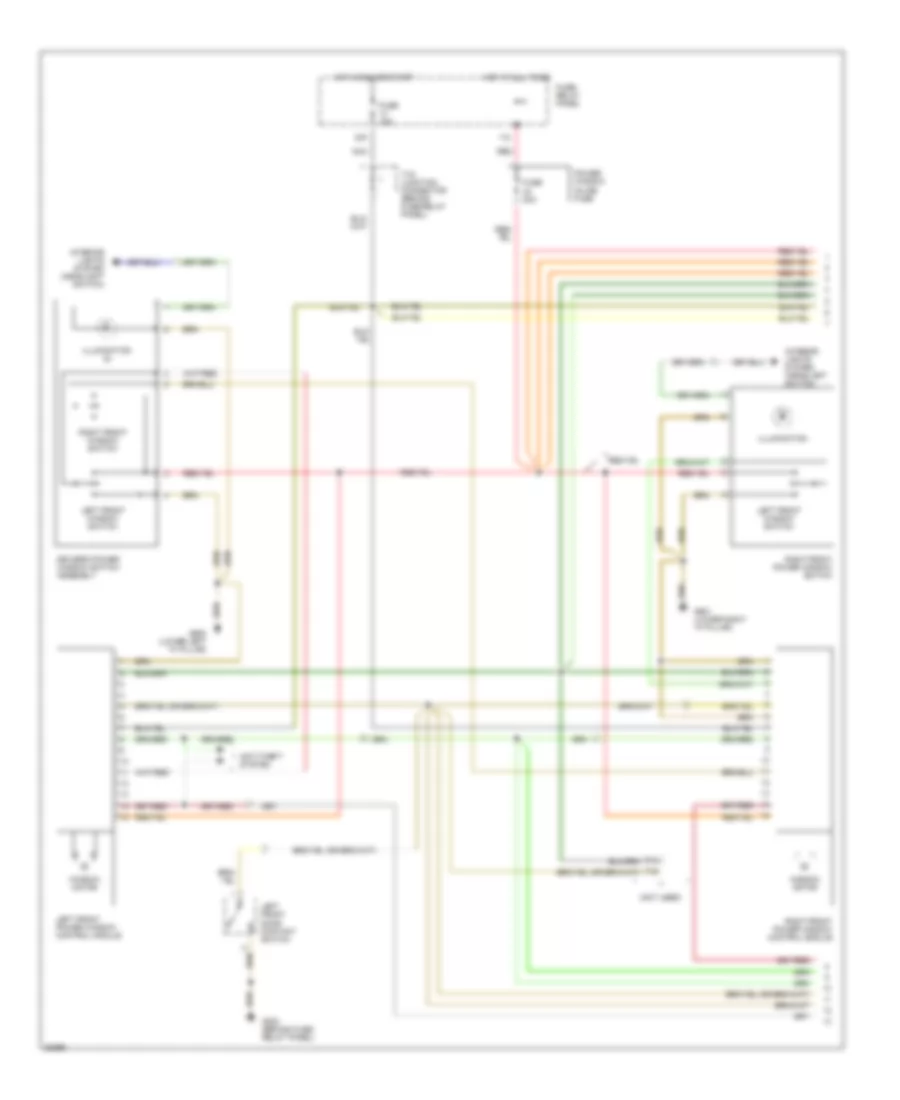
AIR CONDITIONING
2.0L
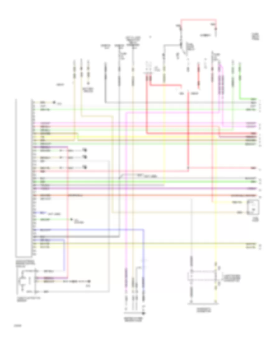
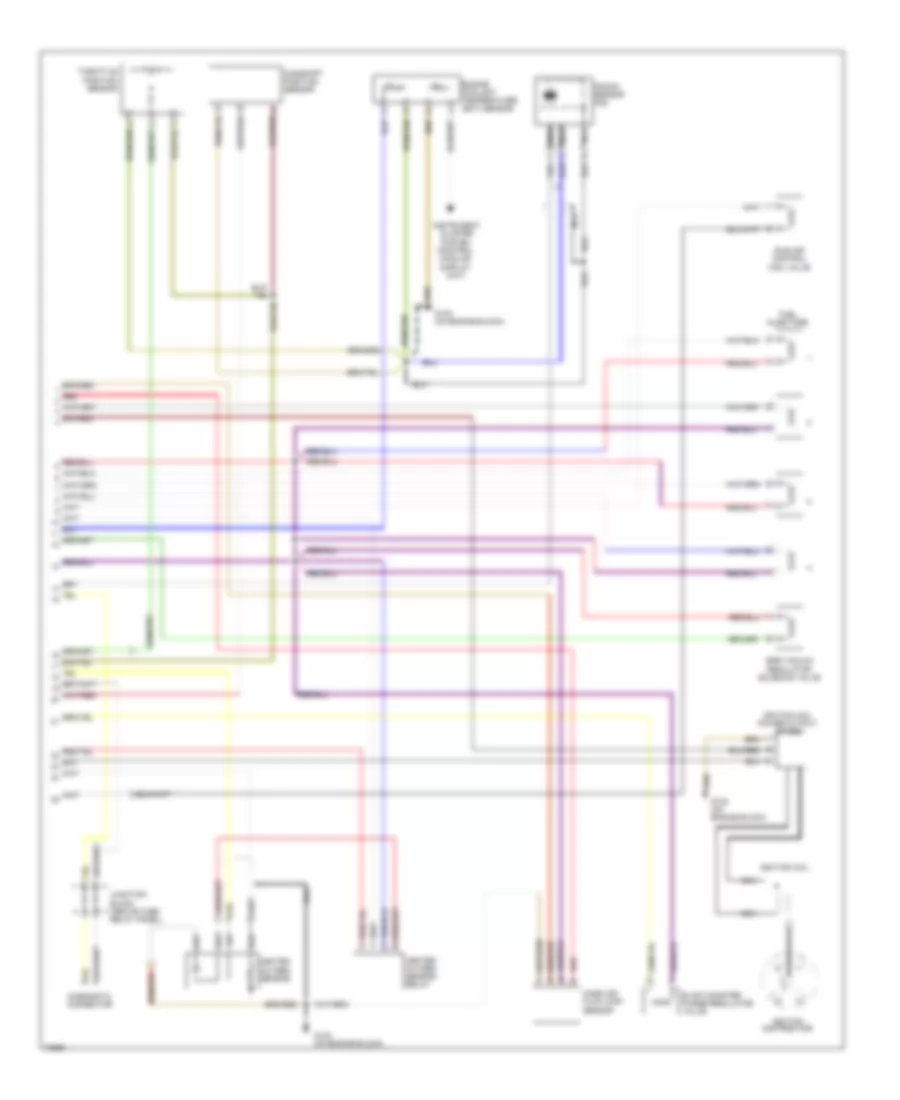
2.0L, A/C Wiring Diagram for Volkswagen Golf III 1995
 https://portal-diagnostov.com/license.html
Automotive Electricians Portal FZCO
Automotive Electricians Portal FZCO
https://portal-diagnostov.com/license.html
https://portal-diagnostov.com/license.html
Automotive Electricians Portal FZCO
Automotive Electricians Portal FZCO
List of elements for 2.0L, A/C Wiring Diagram for Volkswagen Golf III 1995:
- (beside fuse/ relay panel) g202
- (not used)
- 1995 vftc c
- A/c and fresh/recirc switch
- A/c clutch
- A/c cut-out thermal switch (center of engine compt)
- A/c pressure switch (right side of engine compt)
- A/c switch
- A1/5
- Ambient temperature switch (near horn)
- Battery
- Coolant fan
- Coolant fan control module (left side of engine compt)
- Coolant fan control thermoswitch
- D/3
- Fresh air blower
- Fresh air blower series resistance
- Fresh air blower switch
- Fresh/ recirc switch
- Fresh/recirc flap switch
- Fuse 19 30a
- Fuse 20a
- Fuse 4 15a
- Fuse 50a
- Fuse 6 30a
- Fuse/ relay panel
- G100 (behind battery)
- G201 (right side of i/p)
- G202 (beside fuse/ relay panel)
- Hot at all times
- Hot in run
- Interior lights system
- Motronic engine control module
- Q/2
- Red
- T10a
- T2pp
- T41
- T68
- T6g
- Wire connector (above fuse/ relay panel)
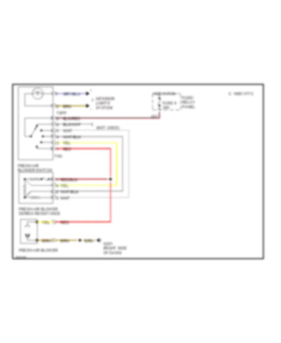
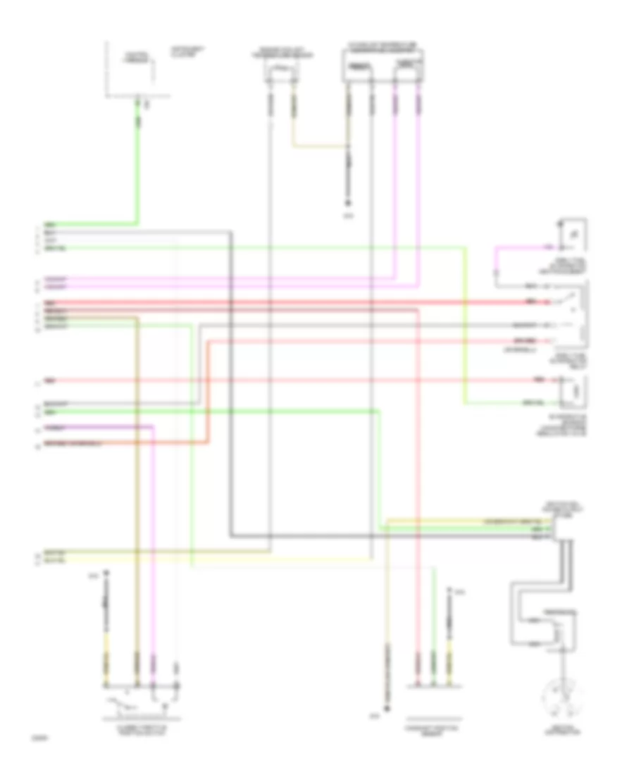
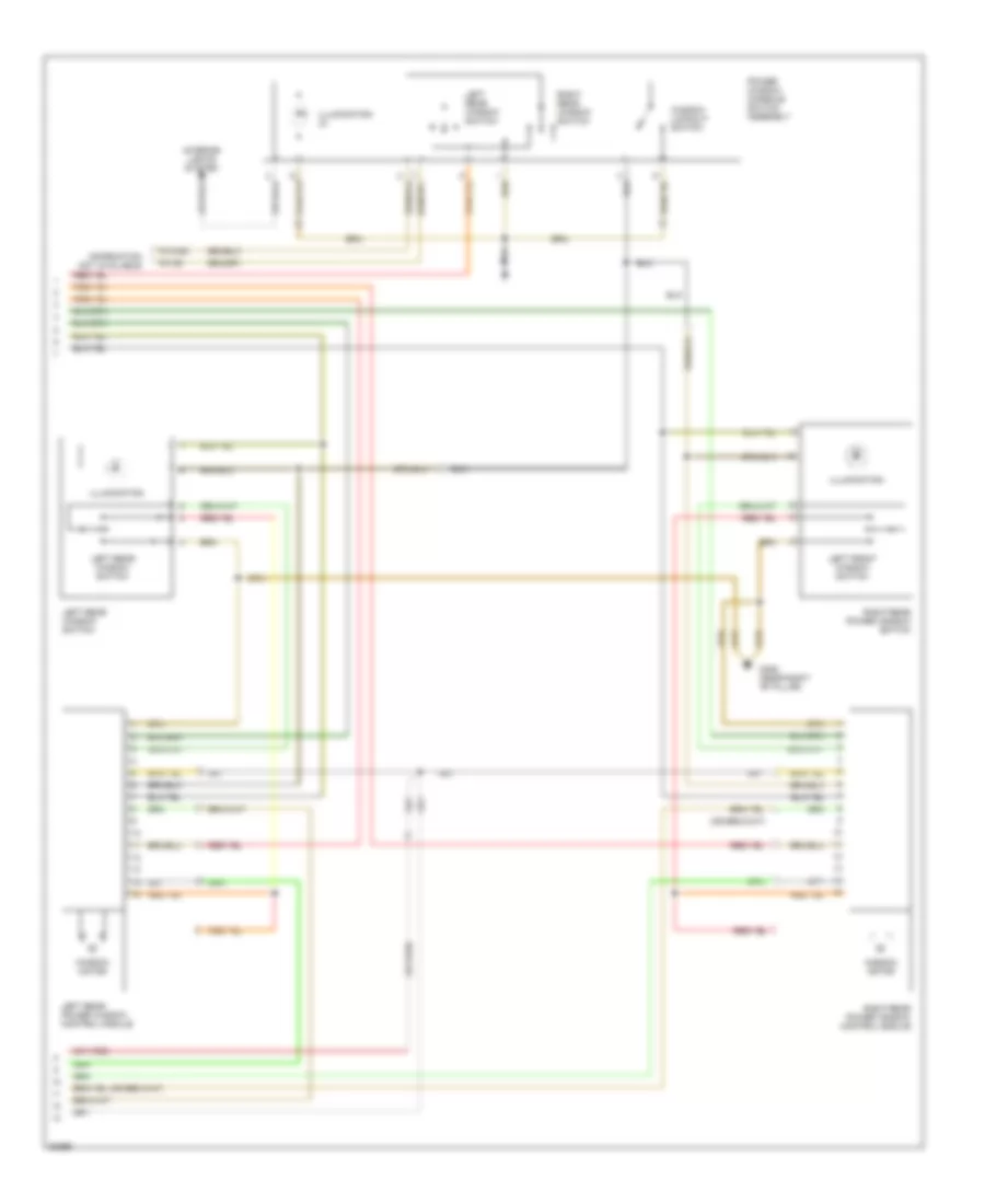
2.0L, Heater Wiring Diagram for Volkswagen Golf III 1995
List of elements for 2.0L, Heater Wiring Diagram for Volkswagen Golf III 1995:
- (not used)
- 1995 vftc c
- Fresh air blower
- Fresh air blower series resistance
- Fresh air blower switch
- Fuse 6 30a
- Fuse/ relay panel
- G201 (right side of dash)
- Hot in run
- Interior lights system
- Q/2
- Red
- T2pp
- T6g
ANTI-LOCK BRAKES
Anti-lock Brake Wiring Diagrams (1 of 2) for Volkswagen Golf III 1995
List of elements for Anti-lock Brake Wiring Diagrams (1 of 2) for Volkswagen Golf III 1995:
- (battery -)
- Abs control module (behind right kick panel)
- Abs main relay (on fuse/ relay panel)
- Auxiliary fuse panel (behind left side of i/p)
- Brake light switch (top of brake pedal support)
- Brake pedal position sensor (mounted on brake booster unit)
- Fuse 20 10a
- Fuse 30a
- Fuse/ relay panel (behind left side of i/p)
- G304 (below left rear seat)
- Hot at all times
- Hot w/ unloader relay energized
- Left front speed sensor capacitor
- Left front wheel speed sensor
- Left rear wheel speed sensor
- Nca
- Red
- Right front speed sensor capacitor
- Right front wheel speed sensor
- Right rear wheel speed sensor
Anti-lock Brake Wiring Diagrams (2 of 2) for Volkswagen Golf III 1995
List of elements for Anti-lock Brake Wiring Diagrams (2 of 2) for Volkswagen Golf III 1995:
- (battery -)
- Abs hydraulic pump relay (on fuse/ relay panel)
- Abs hydraulic pump unit (on brake vacuum booster unit)
- Abs hydraulic unit (under brake master cylinder)
- Abs warning indicator
- Brake fluid lvl warning switch (in master cylinder)
- Data link connector (behind center of i/p)
- Diff lock vlv1
- Diff lock vlv2
- Electronic differential lock cut-off relay (jetta glx)
- Electronic differential lock series resistance (jetta glx)
- Engine control module (at rear of engine compartment)
- Fuse/ relay panel (behind left side of i/p)
- G202 (behind fuse/ relay panel)
- Instrument cluster
- J/b for on-board diagnostics (above fuse/relay panel)
- Left front
- Left rear
- Out
- Parking brake switch (at base of parking brake lever)
- Pres. switch
- Red
- Right front
- Right rear
- T16
- T2a
- T2b
- T2dd
- T68
ANTI-THEFT
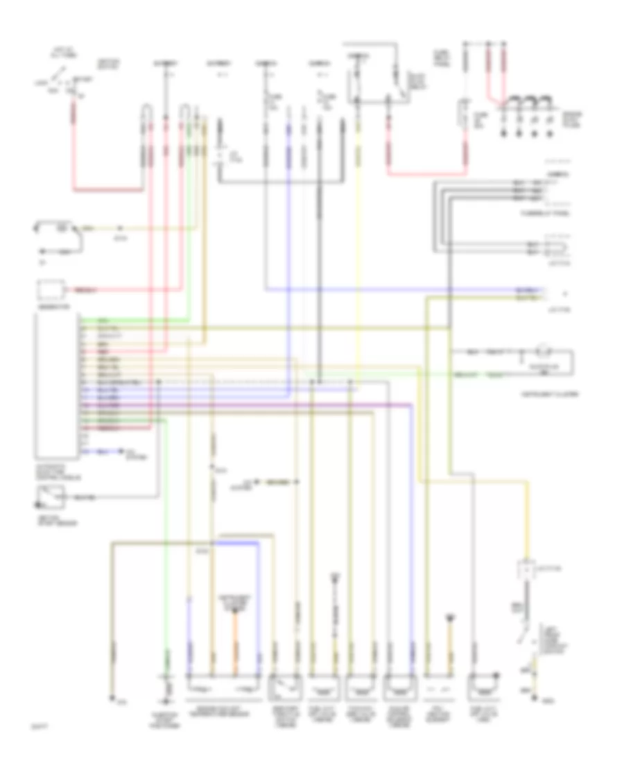
Anti-theft Wiring Diagram for Volkswagen Golf III 1995
List of elements for Anti-theft Wiring Diagram for Volkswagen Golf III 1995:
- Acc
- Alarm horn
- Alarm system control module (behind left side of dash)
- Alarm system indicator light
- Battery
- D/8
- Driver's central locking system door switch
- Exterior lights system
- F/1
- Fuse/ relay panel (behind left side of dash)
- G202 (behind fuse/relay panel)
- G404 (left side of luggage compartment)
- H1/1
- H1/4
- Hood alarm switch
- Hot at all times
- Ignition switch
- Interior lights system
- Left front door contact switch
- Left rear door contact switch
- Left turn signal lamps
- Lock
- Luggage compartment lid alarm switch
- Luggage compartment light switch
- Nca
- Not used
- Passenger's central locking system door switch
- Power sunroof control module
- Power windows, door locks systems
- Radio
- Red
- Right front door contact switch
- Right rear door contact switch
- Right turn signal lamps
- Start
- Starting/charging system (starter)
- T10/1
- T10/10
- T10/2
- T10/3
- T10/4
- T10/5
- T10/6
- T10/7
- T10/8
- T10/9
- T6/1
- T6/2
- T6/3
- T6/4
- T6/5
- T6/6
- T8/1
- Tv2 junction connector (behind fuse/relay panel)
- Tv4 junction connector (behind fuse/relay panel)
- Warning system (left seat belt switch and seat belt warning system relay)
- Y/3
COMPUTER DATA LINES
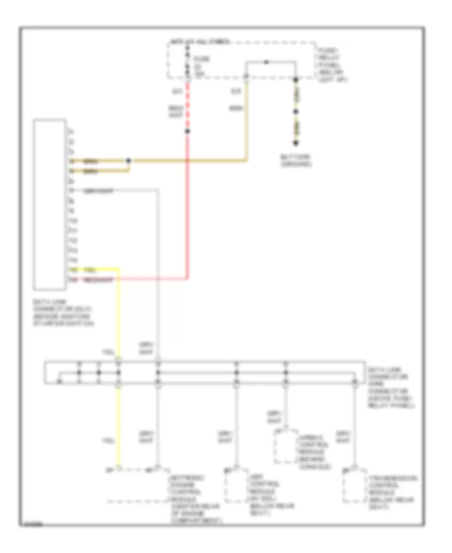
Computer Data Lines for Volkswagen Golf III 1995
List of elements for Computer Data Lines for Volkswagen Golf III 1995:
- Abs control module (w/ edl) (below rear seat)
- Airbag control module (behind console)
- Battery (ground)
- Data link connector (dlc) (beside ignition/ starter switch)
- Data link connector wire connector (above fuse/ relay panel)
- E/5
- Fuse 10a
- Fuse/ relay panel (below left i/p)
- Hot at all times
- Motronic engine control module (center rear of engine compartment)
- Q/3
- Transmission control module (below rear seat)
COOLING FAN
2.0L
2.0L, Cooling Fan Wiring Diagram for Volkswagen Golf III 1995
List of elements for 2.0L, Cooling Fan Wiring Diagram for Volkswagen Golf III 1995:
- (beside fuse/ relay panel) g202
- 1995 vftc c
- A/c clutch
- A/c cut-out thermal switch (center of engine compt)
- A/c pressure switch (right side of engine compt)
- A/c switch
- A1/5
- Ambient temperature switch (near horn)
- Battery
- Coolant fan
- Coolant fan control module (left side of engine compt)
- Coolant fan control thermoswitch
- D/3
- Fuse 19 30a
- Fuse 20a
- Fuse 4 15a
- Fuse 50a
- Fuse/ relay panel
- G100 (behind battery)
- G202 (beside fuse/ relay panel)
- Hot at all times
- Motronic engine control module
- Red
- T10a
- T41
- T68
- Wire connector (above fuse/ relay panel)
CRUISE CONTROL
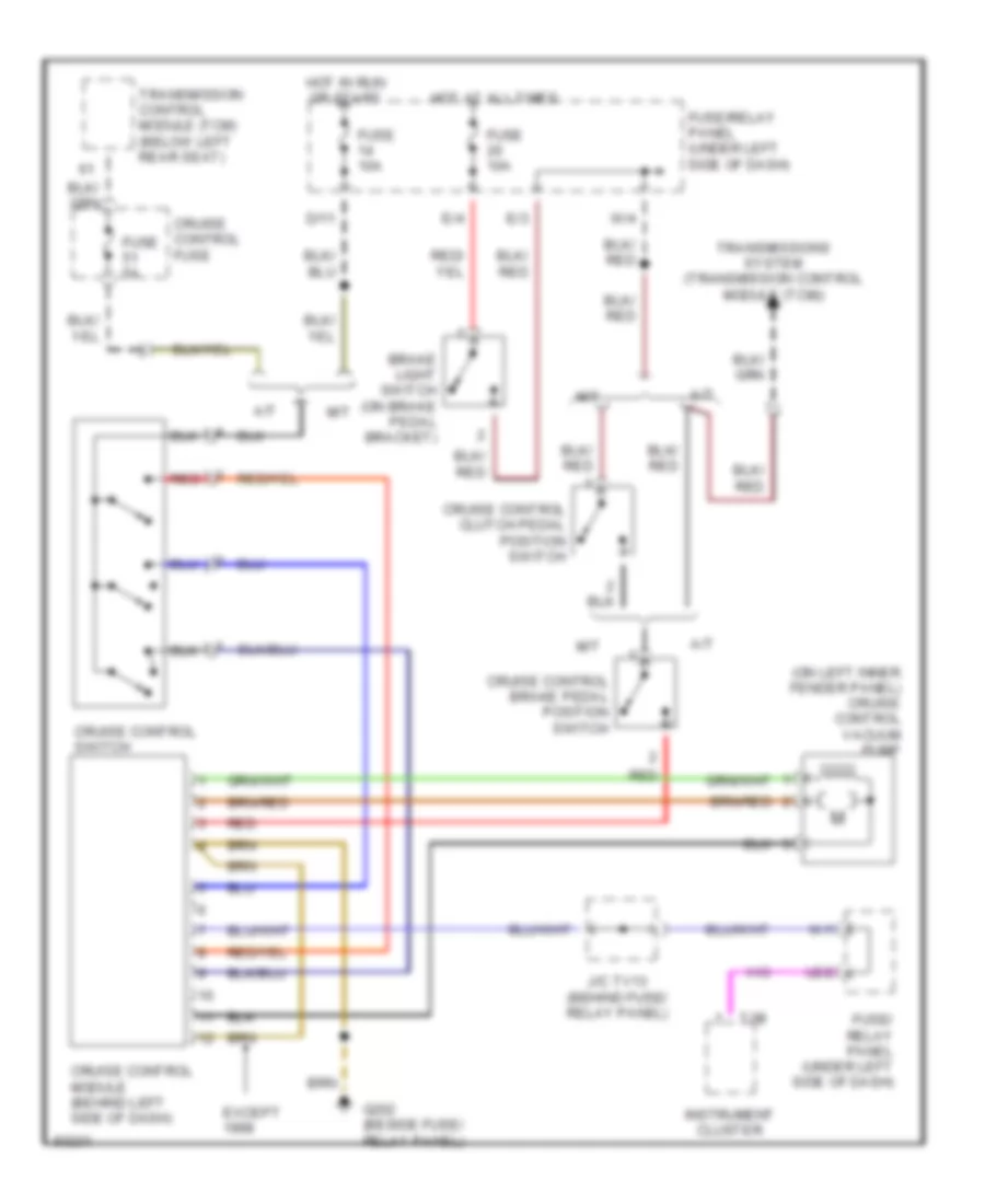
Cruise Control Wiring Diagram for Volkswagen Golf III 1995
List of elements for Cruise Control Wiring Diagram for Volkswagen Golf III 1995:
- (on left inner fender panel) cruise control vacuum pump
- A/t
- Brake light switch (on brake pedal bracket)
- Cruise control brake pedal position switch
- Cruise control clutch pedal position switch
- Cruise control fuse
- Cruise control module (behind left side of dash)
- Cruise control switch
- D/11
- E/3
- E/4
- Except
- Fuse 10a
- Fuse 5a
- Fuse/ relay panel (under left side of dash)
- Fuse/relay panel (under left side of dash)
- G202 (beside fuse/ relay panel)
- Hot at all times
- Hot in run or start
- Instrument cluster
- J/c tv13 (behind fuse/ relay panel)
- M/t
- Red
- T2b
- Transmission control module (tcm) (below left rear seat)
- Transmissions system (transmission control module (tcm))
- U2/2
- W/1
- W/4
DEFOGGERS
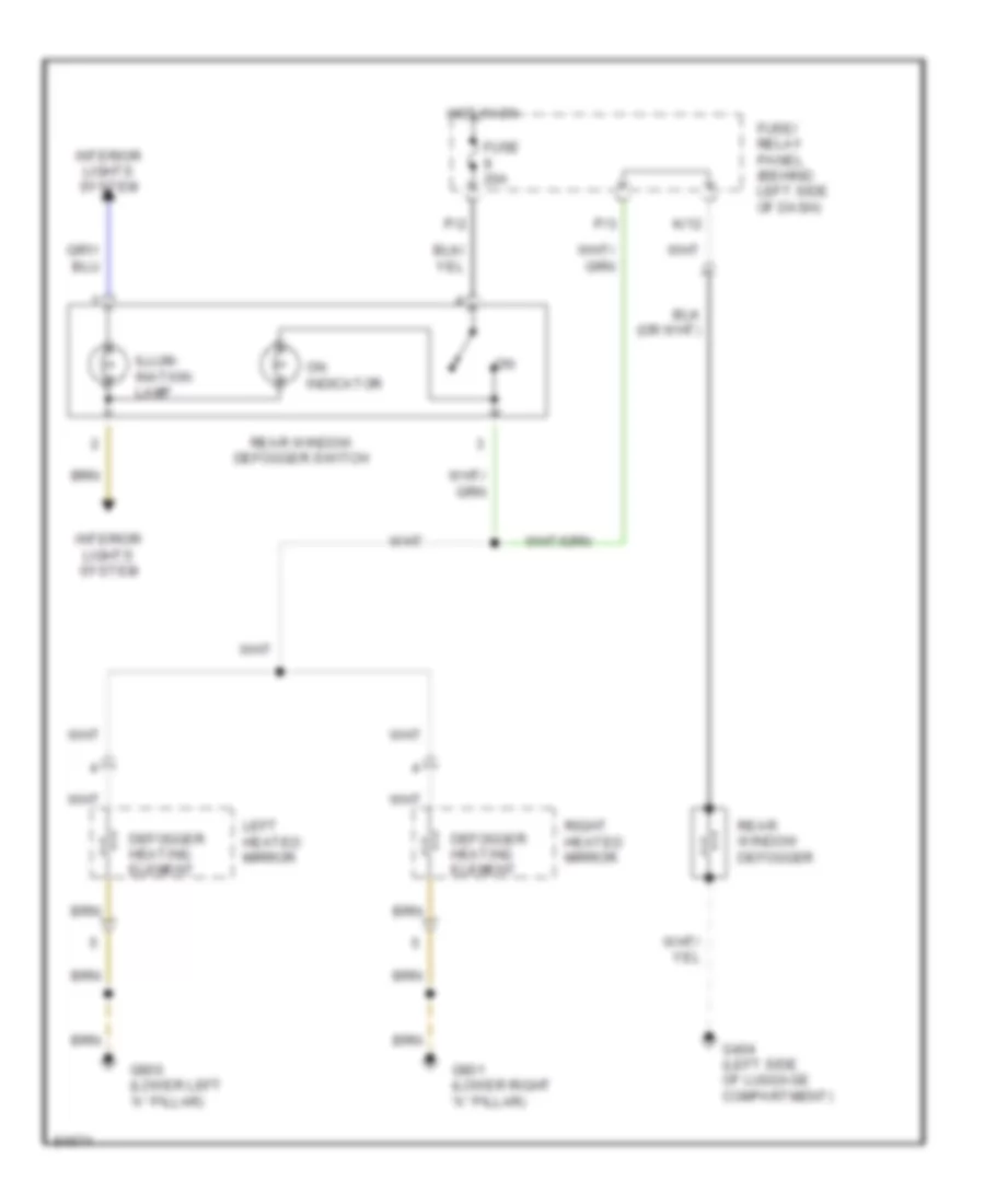
Defogger Wiring Diagram for Volkswagen Golf III 1995
List of elements for Defogger Wiring Diagram for Volkswagen Golf III 1995:
- Defogger heating element
- Fuse 20a
- Fuse/ relay panel (behind left side of dash)
- G404 (left side of luggage compartment)
- G900 (lower left "a" pillar)
- G901 (lower right "a" pillar)
- Hot in on
- Illum- ination lamp
- Interior lights system
- K/12
- Left heated mirror
- On indicator
- P/2
- P/3
- Rear window defogger
- Rear window defogger switch
- Right heated mirror
ENGINE PERFORMANCE
1.8L
1.8L, Engine Performance Wiring Diagrams (1 of 2) for Volkswagen Golf III 1995
List of elements for 1.8L, Engine Performance Wiring Diagrams (1 of 2) for Volkswagen Golf III 1995:
- (not used)
- 1995-97
- 30b
- A/c system
- Battery
- Battery ground
- Diagnostic connector
- F/8
- Fuel pump
- Fuel pump relay
- Fuse 10a
- Fuse 20a
- Fuse/ relay panel
- G1/12
- G1/3
- G1/4
- G1/6
- G1/8
- G15
- G2/4
- G2/8
- G2/9
- Heated oxygen sensor (ho2s)
- Hot w/ load reduction relay energized
- Ignition
- J/c (tv2)
- Junction box for on board diagnostics
- M/1
- M/2
- Mono-motronic engine control module
- Nca
- Red
- T2a
- T2b
- Throttle position sensor
- U1/6
- Z/2
1.8L, Engine Performance Wiring Diagrams (2 of 2) for Volkswagen Golf III 1995
List of elements for 1.8L, Engine Performance Wiring Diagrams (2 of 2) for Volkswagen Golf III 1995:
- Camshaft position sensor
- Closed throttle position switch
- Control module
- Early fuel evaporation heating element
- Early fuel evaporation relay
- Engine coolant temperature sensor
- Evaporative emission canister purge regulator valve
- G15
- Ignition coil
- Ignition coil power output stage
- Ignition distributor
- Injector
- Instrument cluster
- Intake air temperature sensor/fuel injector
- Nca
- Red
- Sensor
- T28
1.9L
1.9L, Engine Performance Wiring Diagram for Volkswagen Golf III 1995
List of elements for 1.9L, Engine Performance Wiring Diagram for Volkswagen Golf III 1995:
- A/c system
- Acc
- Automatic glow time control module
- Battery
- D/11
- D/8
- E/2
- Egr part throttle switch (1995-96)
- Engine coolant temperature sensor
- Engine glow plugs
- F/5
- Fuel cut- off valve (1994)
- Fuel cut- off valve (1995-96)
- Fuse 10a
- Fuse 50a
- Fuse/ relay panel
- Fuse/relay panel
- G1/12
- G1/3
- G1/6
- G15
- G2/4
- G2/5
- G202
- G30
- G78
- Generator
- Glow plug ind
- Glow plug relay
- H1/1
- Hot at all times
- Idle air control solenoid (1995-96)
- Ignition
- Ignition start sensor
- Ignition switch
- Injection start positioner
- Instrument cluster
- Instrument cluster system
- J/c (tv15)
- J/c (tv2)
- J/c (tv4)
- J/c (tv5)
- Left front door contact switch
- Lock
- Nca
- Pcv heating element
- Red
- S119
- S131
- S132
- Start
- T28/13
- T28/20
- Two-way egr valve (1995-96)
- U1/8
- U2/1
- Y/1
- Z/1
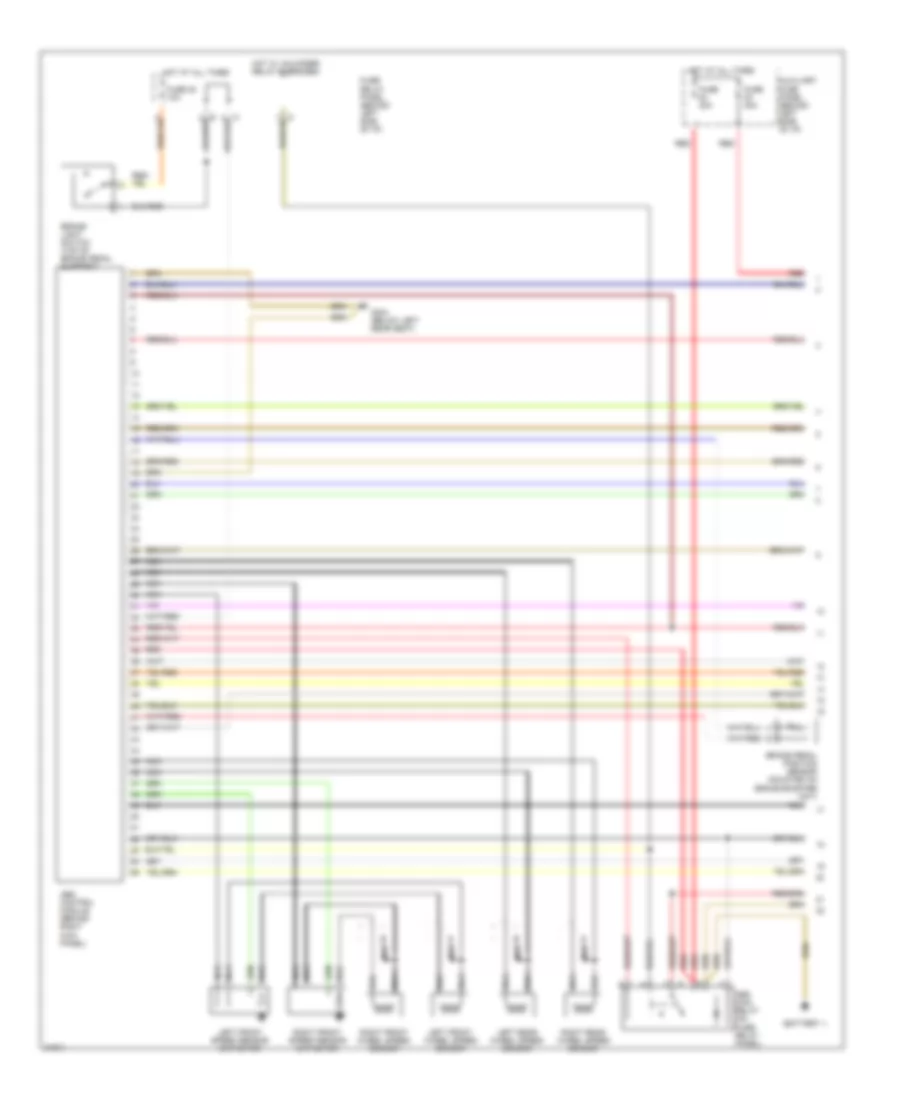
2.0L
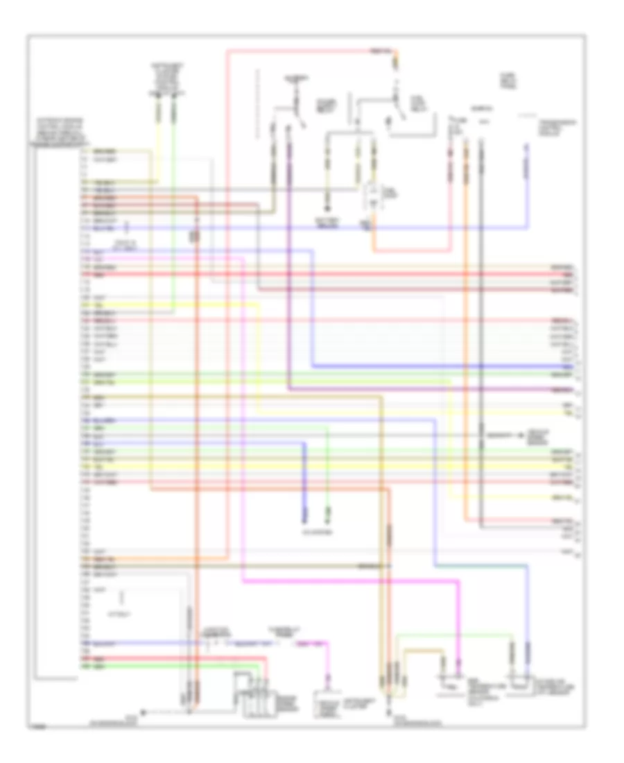
2.0L, Engine Performance Wiring Diagrams (1 of 2) for Volkswagen Golf III 1995
List of elements for 2.0L, Engine Performance Wiring Diagrams (1 of 2) for Volkswagen Golf III 1995:
- (behind firewall, in rear center of engine compartment)
- 86a
- A/c system
- A/t only
- Battery
- Battery ground
- Calif. & n.y. only
- Egr temperature sensor (california only)
- Engine speed sensor
- Fuel pump
- Fuel pump relay
- Fuse 20a
- Fuse/ relay panel
- Fuse/relay panel
- G1/10
- G1/3
- G1/4
- G1/7
- G1/8
- G132 (on engine block)
- G2/9
- Ignition
- Instrument cluster
- Instrument cluster system (control module/ display unit)
- Intake air temperature (iat) sensor
- Junction connector
- M/1
- M/2
- Motronic engine control module
- Nca
- Red
- Transmission control module
- U2/2
- Vehicle speed sensor
- Vehicle speed signal
- W/1
- Z/2
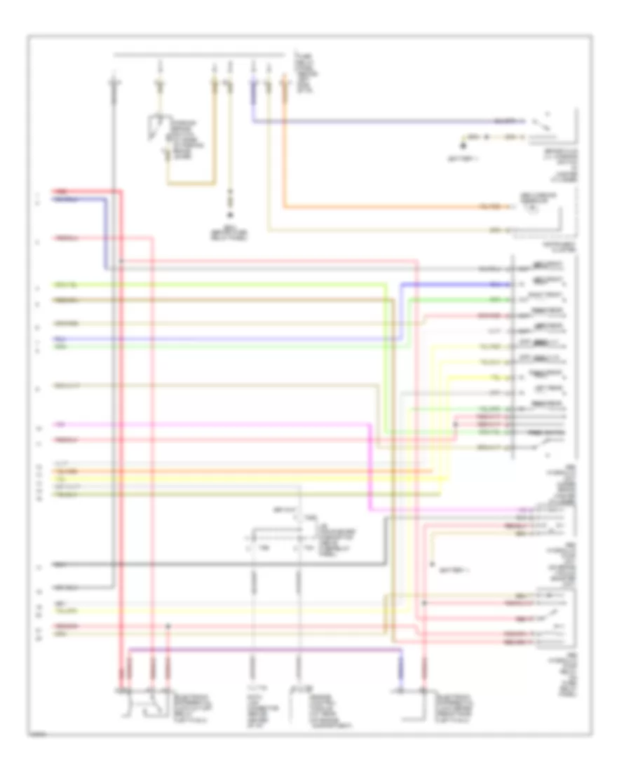
2.0L, Engine Performance Wiring Diagrams (2 of 2) for Volkswagen Golf III 1995
List of elements for 2.0L, Engine Performance Wiring Diagrams (2 of 2) for Volkswagen Golf III 1995:
- Camshaft position sensor
- Diagnostic connector
- Egr vacuum regulator solenoid valve
- Engine coolant temperature (ect) sensor
- Evap canister purge regulator valve
- Fuel injectors
- G132 (on engine block)
- Heated oxygen sensor
- Heated oxygen sensor relay
- Idle air control (iac) valve
- Ignition coil
- Ignition coil power output stage
- Ignition distributor
- Instrument cluster system (control module/ display unit)
- Junction block (above fuse/ relay panel)
- Knock sensor (ks)
- Mass air flow (maf) sensor
- Nca
- Red
- Throttle position sensor
EXTERIOR LIGHTS
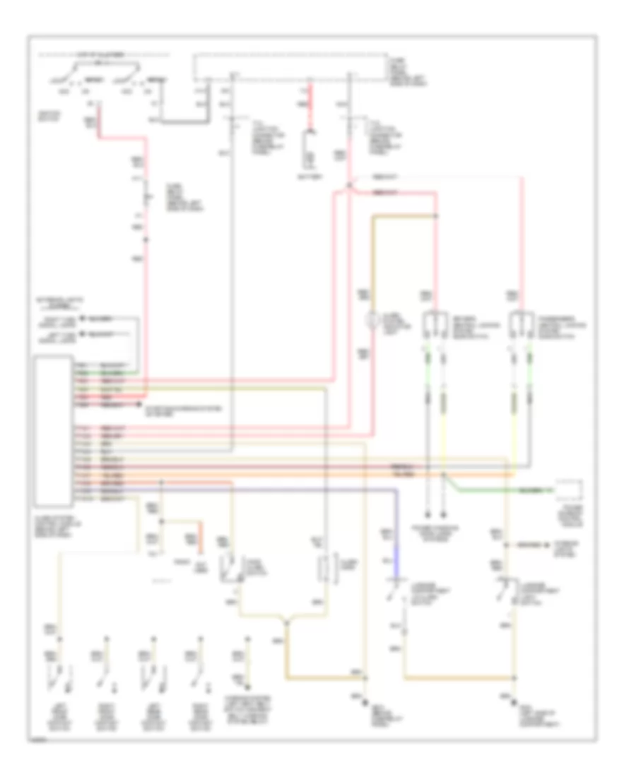
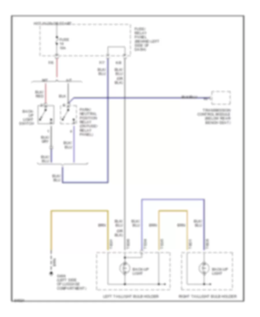
Back-up Lamps Wiring Diagram for Volkswagen Golf III 1995
List of elements for Back-up Lamps Wiring Diagram for Volkswagen Golf III 1995:
- A/t
- Back- up light switch
- Back-up light
- F/6
- F/7
- Fuse 10a
- Fuse/ relay panel (behind left side of dash)
- G404 (left side of luggage compartment)
- Hot in on or start
- K/8
- Left taillight bulb holder
- M/t
- Park/ neutral position relay (on fuse/ relay panel)
- Right taillight bulb holder
- T5d/4
- T5d/5
- T8d/1
- T8d/6
- T8e/1
- T8e/6
- Transmission control module (below rear bench seat)
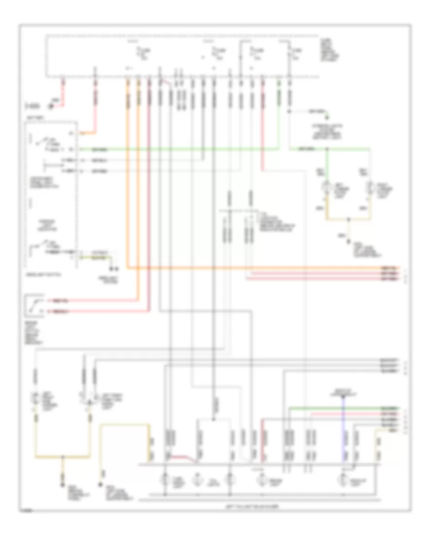
Exterior Lamps Wiring Diagram (1 of 2) for Volkswagen Golf III 1995
List of elements for Exterior Lamps Wiring Diagram (1 of 2) for Volkswagen Golf III 1995:
- (not used)
- 58l
- 58r
- A1/4
- A2/2
- Back-up lamps circuit
- Back-up light
- Battery
- Brake light
- Brake light switch (brake pedal bracket)
- E/3
- E/4
- Fuse 10a
- Fuse/ relay panel (behind left side of dash)
- G202 (behind fuse/relay panel)
- G404 (left side of luggage compartment)
- Head
- Headlight switch
- Headlight system
- Instrument panel light dimmer switch
- Interior lights system (center rear ashtray light)
- J/4
- K/10
- K/2
- K/3
- K/4
- K/5
- Left front park/turn signal light
- Left front side marker light
- Left license plate light
- Left taillight bulb holder
- Off
- P/6
- Park
- Parking light indicator
- R/2
- R/5
- R/6
- R/7
- Red
- Right license plate light
- T19 junction connector (behind center of radiator grille)
- T1v
- T5d/2
- T5d/3
- T5d/4
- T5d/5
- T8d/1
- T8d/2
- T8d/3
- T8d/4
- T8d/5
- T8d/6
- T8d/7
- T8d/8
- Tail lights
- Turn signal light
- W/4
- Y/3
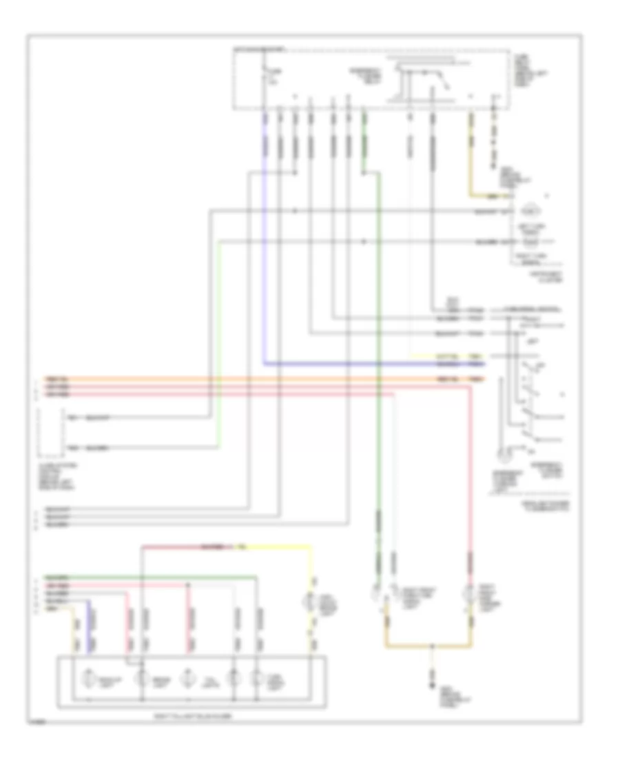
Exterior Lamps Wiring Diagram (2 of 2) for Volkswagen Golf III 1995
List of elements for Exterior Lamps Wiring Diagram (2 of 2) for Volkswagen Golf III 1995:
- A1/2
- A2/4
- Alarm system control module (behind left side of dash)
- Back-up light
- Brake light
- Emergency flasher relay
- Emergency flasher switch
- Emergency flasher warning light
- Fuse 10a
- Fuse/ relay panel (behind left side of dash)
- G202 (behind fuse/relay panel)
- H1/5
- H2/4
- H2/6
- H2/8
- Headlight/dimmer flasher/switch
- High- mount brake light
- Hot in on or start
- Instrument cluster
- J/8
- K/1
- K/7
- Left
- Left turn signal
- Off
- Right
- Right front park/turn signal light
- Right front side marker light
- Right taillight bulb holder
- Right turn signal
- T3e/2
- T4c/4
- T5b/1
- T5b/5
- T6/1
- T6/2
- T7a/2
- T7a/3
- T7a/7
- T8e/1
- T8e/2
- T8e/3
- T8e/6
- T8e/7
- T8e/8
- Tail lights
- Turn signal light
- Turn signal switch
- U1/10
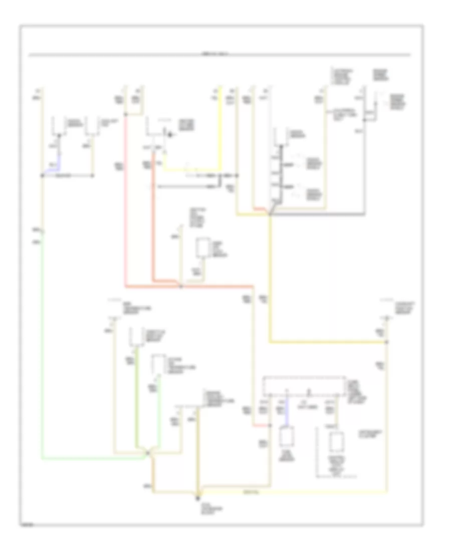
GROUND DISTRIBUTION
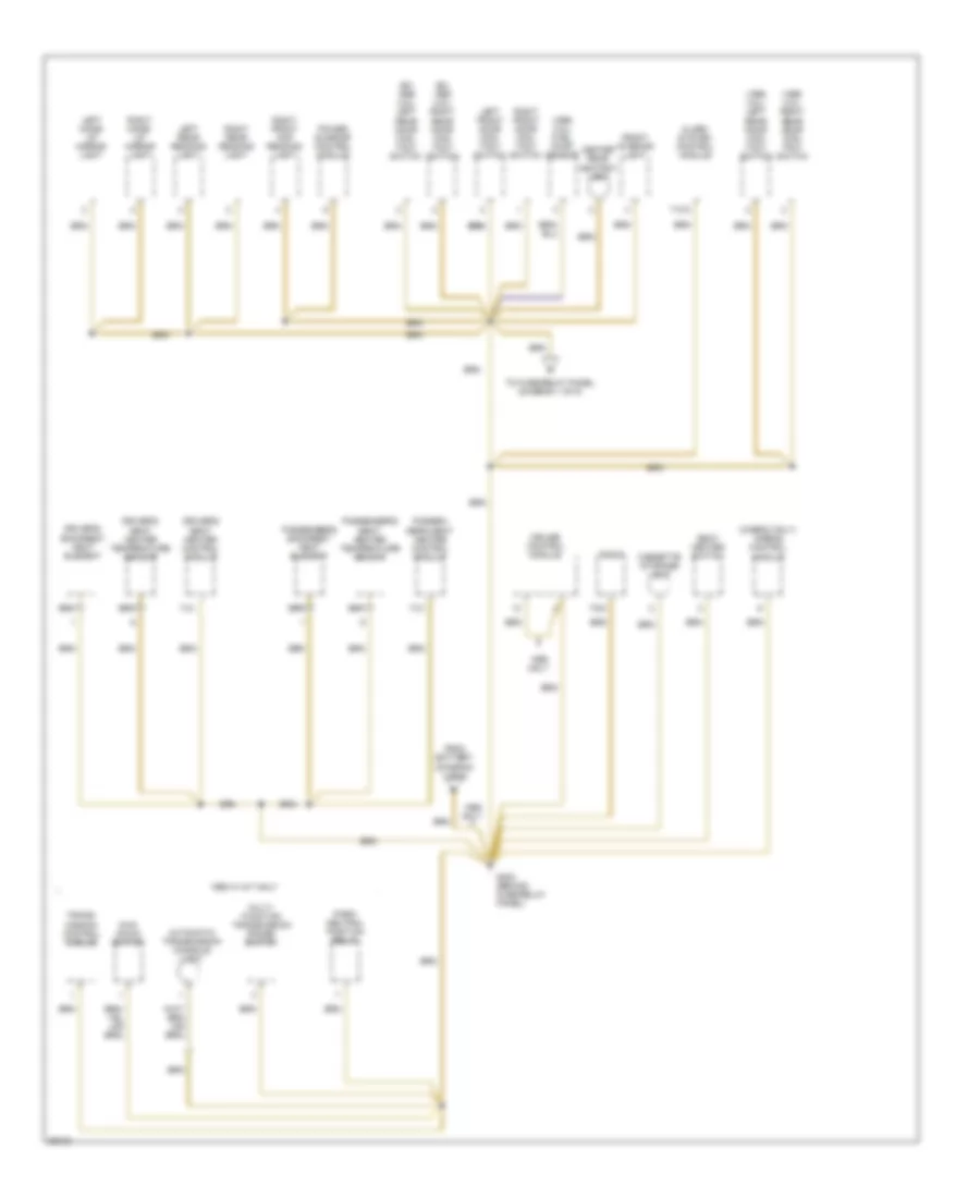
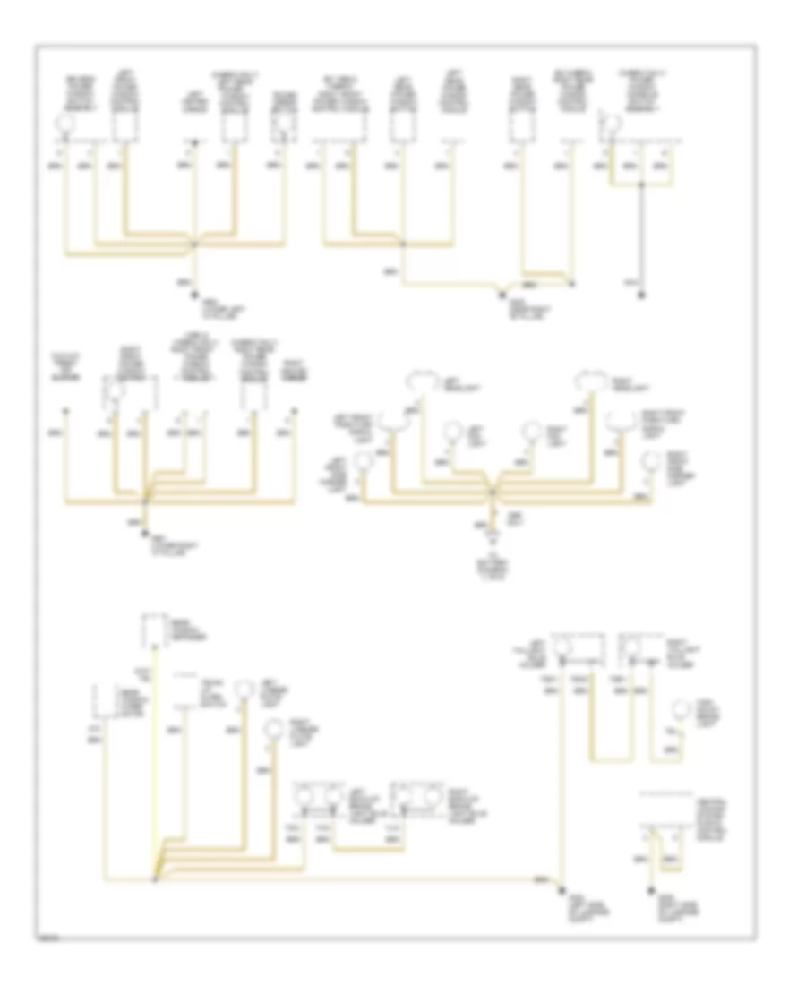
Ground Distribution Wiring Diagram (1 of 6) for Volkswagen Golf III 1995
List of elements for Ground Distribution Wiring Diagram (1 of 6) for Volkswagen Golf III 1995:
- (1996) ashtray light
- (body)
- (cabrio & 1995)
- (ex cabrio & 1995)
- (not used)
- (not used) (above fuse relay panel)
- (trans- mission)
- (w/ a/c) coolant fan control module
- 0nly
- 1/31
- 1/85
- 1995 only
- 2/31
- 3/30
- 4/85
- 5/31
- 9/31
- A/c switch
- Abs control module (1995 golf,gti, jetta)
- Abs control module (1996, cabrio)
- Abs warning light
- Airbag malfunction indicator lamp
- Alarm horn
- Battery
- Brake fluid level warning switch
- Cigarette lighter
- Coolant fan (1995 2.8l)
- Coolant fan (w/ a/c)
- Data link connector
- Dual horn relay
- Emergency flasher relay
- Engine coolant level sensor
- F/4
- F/8
- Fog light relay
- Fresh air blower (w/ a/c)
- Fresh air control lever light
- Fresh air/ recircu- lating flap two- way valve (w/ a/c)
- From center rear ashtray light (diagram 2 of 6)
- From g132 (diagram 4 of 6)
- From headlights (diagram 3 of 6)
- Fuel pump
- Fuse/ relay panel (under left side of dash)
- G1/11
- G1/6
- G132 (on engine block)
- G201 (behind right side of i/p)
- G304 (below left rear seat bench)
- Glove compart- ment light
- H1/6
- Headlight switch
- Hood alarm switch
- Instrument cluster
- K/11
- L/1
- Left brake pad wear indicator
- Left washer nozzle heater
- Load reduction relay
- Luggage compartment release switch
- M/1
- Multi- function transmission range switch (1996 golf,gti, jetta)
- Nca
- P/5
- Park/ neutral position relay (1996 golf,gti, jetta)
- Parking brake warning light switch
- Q/1
- R/8
- Rear window defogger switch
- Rear window wiper/ washer relay
- Right brake pad wear indicator
- Right washer nozzle heater
- S/3
- Seat belt warning system relay
- T28/14
- T28/3
- T4c/3
- T6b/3
- T9/7
- To g202 (diagram 2 of 6)
- U1/10
- Washer/ wiper intermittent relay
- Windshield wiper motor
- Windshield wiper/washer switch & horn switch
- X/2
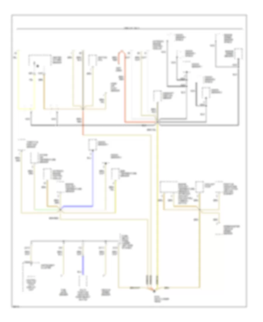
Ground Distribution Wiring Diagram (2 of 6) for Volkswagen Golf III 1995
List of elements for Ground Distribution Wiring Diagram (2 of 6) for Volkswagen Golf III 1995:
- (1995 2.8l) fuel pump sensor
- (1995 2.8l) left rear door con- tact switch
- (1995 2.8l) right rear door con- tact switch
- (cabrio only) airbag control module
- (ex 2.8l) left rear door con- tact switch
- (ex 2.8l) right rear door con- tact switch
- 1995 w/ a/t only
- 7/31
- Alarm system control module
- Automatic transmission console light
- Cassette storage light
- Center rear ashtray light
- Cruise control module
- Driver's backrest heat element
- Driver's seat heater control module
- Driver's seat heater temperature sensor
- From battery (diagram 1 of 6)
- Front interior light
- G202 (behind fuse/relay panel)
- Kick down switch
- Left front door con- tact switch
- Left make- up mirror light
- Left rear reading light
- Multi- function transmission range switch
- Only
- Park/ neutral position relay
- Passen- ger's seat heater control module
- Passenger's backrest heat element
- Passenger's seat heater temperature sensor
- Power sunroof control module
- Radio
- Right front door con- tact switch
- Right front map reading light
- Right make- up mirror light
- Right rear reading light
- Seat heater switch
- T10/3
- T8/8
- To fuse/relay panel (diagram 1 of 6)
- Trans- mission control module
Ground Distribution Wiring Diagram (3 of 6) for Volkswagen Golf III 1995
List of elements for Ground Distribution Wiring Diagram (3 of 6) for Volkswagen Golf III 1995:
- (1996 & cabrio only)
- (cabrio only) left rear
- (cabrio only) power window console switch assembly
- (cabrio only) right rear power window control module
- (ex 1996 & cabrio) right front power window control module
- (ex cabrio) right rear power window control module
- (w/o a/c) fresh air blower
- 2/31
- Central locking system pump & control module
- Driver's power window switch assembly
- G305 (near right "b" pillar)
- G404 (left side of luggage compt)
- G405 (right side of luggage compt)
- G900 (lower left "a" pillar)
- G901 (lower right "a" pillar)
- High- mount brake light
- Left back-up/ brake light bulb holder
- Left fog light
- Left front park/turn signal light
- Left front power window control module
- Left front side marker light
- Left headlight
- Left heated mirror
- Left license plate light
- Left rear power window control module
- Left rear power window switch
- Left taillight bulb holder
- Nca
- Only
- Power
- Power mirror switch
- Power window control module
- Rear window defogger
- Rear window wiper motor
- Right back-up/ brake light bulb holder
- Right fog light
- Right front
- Right front park/turn signal light
- Right front power window switch
- Right front side marker light
- Right headlight
- Right heated mirror
- Right license plate light
- Right rear power window switch
- Right taillight bulb holder
- T5d/5
- T8d/1
- T8e/1
- Tg/2
- Th/2
- Tj/2
- To battery (diagram (1 of 6)
- Trunk lid alarm switch
- Window control module
Ground Distribution Wiring Diagram (4 of 6) for Volkswagen Golf III 1995
List of elements for Ground Distribution Wiring Diagram (4 of 6) for Volkswagen Golf III 1995:
- (2.0l)
- (2.8 only) coolant pump
- (2.8l)
- (under left side of dash) fuse/relay panel
- (w/ a/c) fresh air blower
- 1996 only
- 2.0l
- 2.0l only
- 2.8l
- 2.8l: igni- tion coil; 2.0l: igni- tion coil power out- put stage
- A/c clutch (cabrio w/ a/c)
- A/c clutch (w/ a/c ex 2.8l & (cabrio)
- A/c cut- off relay (w/ a/c ex 2.8l & cabrio)
- Alarm horn
- Automatic transmission console light (w/ a/t)
- Brake fluid level warning switch
- Cabrio
- Camshaft position sensor
- Control module with display unit
- Coolant fan
- Coolant fan (2.8l & cabrio, w/ a/c)
- Coolant fan (w/ a/c ex 2.8l & cabrio)
- Coolant fan control module (2.8l & cabrio, w/ a/c)
- Coolant fan control module (w/ a/c ex 2.8l & cabrio)
- Engine coolant level sensor (a/t only)
- Engine coolant temperature sensor
- Engine speed sensor
- Ex cabrio
- Fresh air/ recircu- lating flap two- way valve (2.8l & cabrio, w/ a/c)
- Fresh air/ recirculating flap two- way valve (w/ a/c ex 2.8l & cabrio)
- Front side marker lights
- Fuel level sensor
- G1/5
- G132 (on engine block)
- G201 (right side of i/p)
- G202 (beside fuse relay panel)
- Heated oxygen sensor 1 shield
- Heated oxygen sensor 2 shield
- Heated oxygen sensor 2 shield (2.8l only)
- Hood alarm switch
- Instru- ment cluster
- Kick down switch (w/ a/t)
- Knock sensor 1
- Knock sensor 1 shields
- Knock sensor 2 (2.8 only)
- Left fog light
- Left front park/ turn signal light
- Left head- light
- M/6
- Mass air flow sensor
- Mo- tronic engine control module
- Motronic engine control module
- Multi- function indicator mode select switch (jetta)
- Multi- function trans- mission range switch (w/ a/t)
- Nca
- Park/ neutral position relay (w/ a/t)
- Relay for a/c shut- off (cabrio w/ a/c)
- Right fog light
- Right front park/ turn signal light
- Right head- light
- Right seat belt module (2.0l only)
- Secondary air injection pump motor
- Speed- ometer vehicle speed sensor (a/t only)
- Speed- ometer vehicle speed sensor (m/t only)
- T28/5
- T68/1
- T68/58
- T68/7
- T9/3
- To battery (diagram 1 of 6)
- To fuse/relay panel (diagram 1 of 6)
- Trans- mission control module (w/ a/t)
- U2/13
Ground Distribution Wiring Diagram (5 of 6) for Volkswagen Golf III 1995
List of elements for Ground Distribution Wiring Diagram (5 of 6) for Volkswagen Golf III 1995:
- (-)
- (not used)
- 1995 2.0l only
- California & new york only
- Camshaft position sensor
- Control module with display unit
- Coolant fan
- Egr temperature sensor
- Engine coolant temperature sensor
- Engine speed sensor
- Engine speed sensor shield
- Fuel level sensor
- Fuse/ relay panel (under left side of dash)
- G1/5
- G132 (on engine block)
- Heated oxygen sensor
- Ignition coil power output stage
- Instrument cluster
- Intake air temperature sensor
- Knock sensor
- Knock sensor shield
- M/6
- Mass air flow sensor
- Motronic engine control module
- Nca
- T28/5
- Throttle position sensor
- U2/13
- V/2
Ground Distribution Wiring Diagram (6 of 6) for Volkswagen Golf III 1995
List of elements for Ground Distribution Wiring Diagram (6 of 6) for Volkswagen Golf III 1995:
- (not used)
- 1995 2.8l only
- Camshaft position sensor
- Control module with display unit
- Coolant pump
- Egr temperature sensor
- Engine coolant temperature sensor
- Engine coolant temperature sensor & after run coolant fan control thermal switch
- Engine speed sensor
- Engine speed sensor shield
- Fuel level sensor
- Fuse/ relay panel (under left side of dash)
- G1/11
- G1/5
- G132 (on cylinder head)
- Heated oxygen sensor
- Ignition coil
- Instrument cluster
- Intake air temperature sensor
- Knock sensor 1
- Knock sensor 1 shield
- Knock sensor 2
- Knock sensor 2 shield
- M/6
- Mass air flow sensor
- Motronic engine control module
- Multi- function indicator mode select switch
- Nca
- Positive crankcase ventilation heating element
- Speedometer vehicle speed sensor
- T28/5
- Throttle position sensor
- U2/13
- V/2
- Vehicle speed sensor
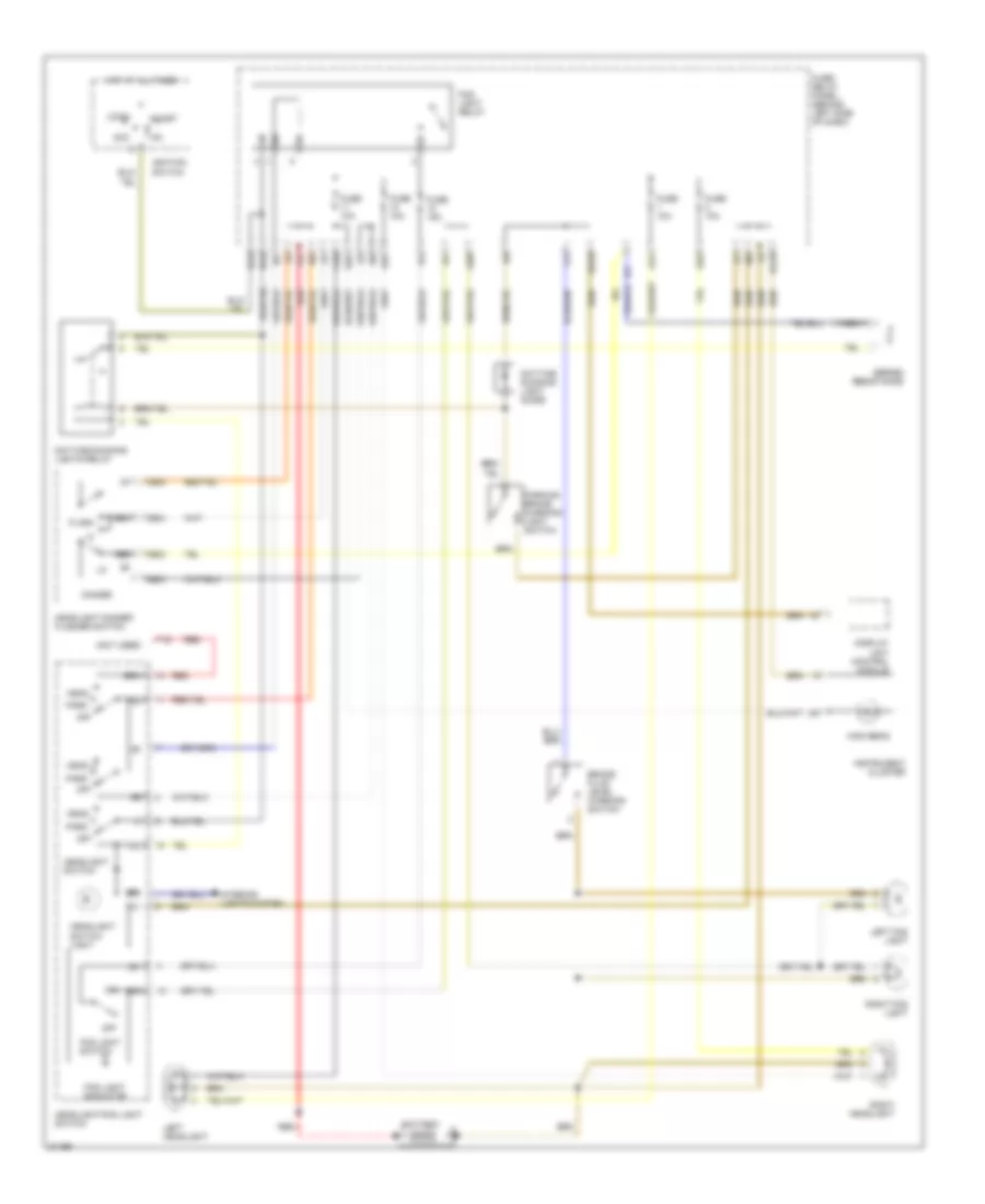
HEADLIGHTS
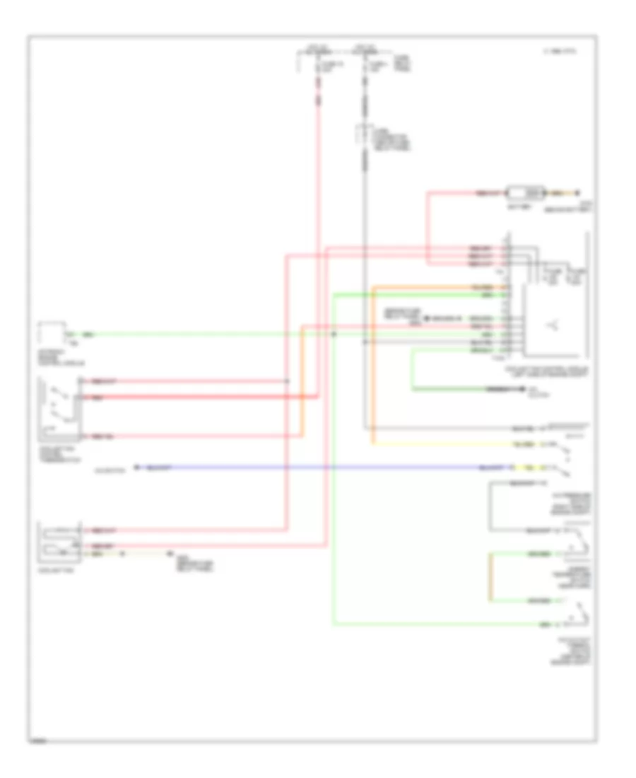
Headlight Wiring Diagram, with DRL for Volkswagen Golf III 1995
List of elements for Headlight Wiring Diagram, with DRL for Volkswagen Golf III 1995:
- (not used)
- 56a
- 56b
- 58b
- 83a
- A1/1
- A1/6
- A2/3
- A2/7
- A2/8
- Acc
- Battery
- Brake fluid level warning switch
- C/1
- Daytime running light diode
- Daytime running lights relay
- Dimmer
- Display unit control module
- Flash
- Fog light indicator
- Fog light relay
- Fog light switch
- Fuse 10a
- Fuse 15a
- Fuse/ relay panel (behind left side of dash)
- H1/3
- Head
- Headlight dimmer/ flasher switch
- Headlight switch
- Headlight switch light
- Headlight/fog light switch
- High beam
- Hot at all times
- Ignition switch
- Instrument cluster
- Interior lights system
- J/1
- J/2
- J/3
- J/4
- L/1
- L/6
- Left fog light
- Left headlight
- Lock
- Nca
- Off
- P/1
- P/4
- Park
- Parking brake warning light switch
- R/10
- R/5
- R/7
- R/8
- R/9
- Red
- Right fog light
- Right headlight
- Series resistance
- Sra
- Start
- T1q
- T5b/2
- T5b/3
- T5b/4
- T5b/5
- Tfl
- U1/10
- U2/10
- U2/7
- Y/3
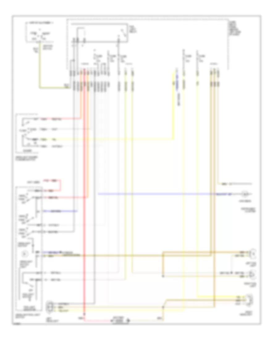
Headlight Wiring Diagram, without DRL for Volkswagen Golf III 1995
List of elements for Headlight Wiring Diagram, without DRL for Volkswagen Golf III 1995:
- (not used)
- 56a
- 56b
- 58b
- 83a
- A1/1
- A1/6
- A2/3
- A2/7
- A2/8
- Acc
- Battery
- Dimmer
- Flash
- Fog light indicator
- Fog light relay
- Fog light switch
- Fuse 10a
- Fuse 15a
- Fuse/ relay panel (behind left side of dash)
- H1/3
- Head
- Headlight dimmer/ flasher switch
- Headlight switch
- Headlight switch light
- Headlight/fog light switch
- High beam
- Hot at all times
- Ignition switch
- Instrument cluster
- Interior lights system
- J/1
- J/2
- J/3
- J/4
- Left fog light
- Left headlight
- Lock
- Off
- P/1
- P/4
- Park
- R/10
- R/5
- R/7
- R/8
- R/9
- Red
- Right fog light
- Right headlight
- Sra
- Start
- T1q
- T5b/2
- T5b/3
- T5b/4
- T5b/5
- U1/10
- U2/7
- Y/3
HORN
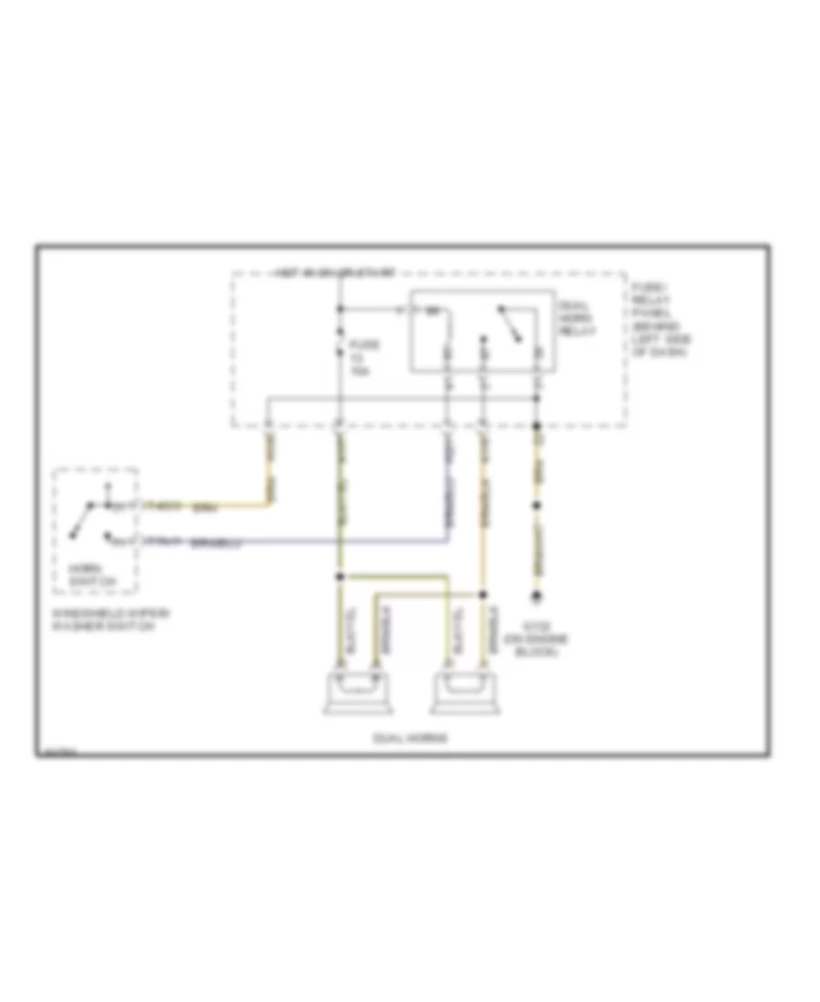
Horn Wiring Diagram for Volkswagen Golf III 1995
List of elements for Horn Wiring Diagram for Volkswagen Golf III 1995:
- A1/7
- A1/8
- Dual horn relay
- Dual horns
- Fuse 10a
- Fuse/ relay panel (behind left side of dash)
- G132 (on engine block)
- H1/6
- H2/1
- Horn switch
- Hot in on or start
- T4c/3
- T7a/1
- Windshield wiper/ washer switch
INSTRUMENT CLUSTER
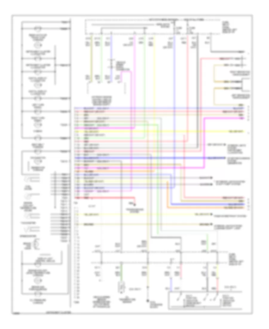
Instrument Cluster Wiring Diagram (1 of 2) for Volkswagen Golf III 1995
List of elements for Instrument Cluster Wiring Diagram (1 of 2) for Volkswagen Golf III 1995:
- (2.8l only)
- Brake and parking brake
- Brake pad wear
- Digital display illumination
- Display unit control module
- Engine coolant level/temperature warning
- Engine coolant temperature gauge
- Exterior lights system & anti-theft system
- Fuel gauge
- Fuse 10a
- Fuse 15a
- Fuse/ relay panel (behind left side of i/p)
- G1/11
- G1/12
- G1/5
- G1/9
- G132 (on engine block)
- G2/1
- Generator warning
- Headlights system
- Hi-beam
- Hot at all times
- Hot with headlights on
- Instrument cluster
- Instrument cluster illumination
- Interior lights system (instrument illumination)
- Interior lights system (luggage compt. lamp)
- Left brake pad wear element
- Left turn signal
- Malfunction
- Motronic engine control module (center rear of engine compt)
- Mult- function indicator memory switch
- Mult- function indicator mode select switch
- Nca
- Oil pressure warning
- Oil temperature sensor
- Passive restraint system
- Rear hatch or trunk ajar warning
- Red
- Right brake pad wear element
- Right turn signal
- Seat belt warning
- Speedometer
- Starting/charging system (generator)
- T28
- T28/1
- T28/10
- T28/11
- T28/12
- T28/13
- T28/14
- T28/15
- T28/16
- T28/17
- T28/18
- T28/19
- T28/2
- T28/20
- T28/21
- T28/22
- T28/23
- T28/24
- T28/25
- T28/26
- T28/27
- T28/28
- T28/3
- T28/4
- T28/5
- T28/6
- T28/7
- T28/8
- T28/9
- T28b
- T28b/3
- T28b/6
- Tachometer
- Transmissions system
- U1/1
- U1/11
- U1/6
- U1/9
- U2/1
- U2/11
- U2/13
- U2/14
- U2/2
- U2/4
- U2/7
- U2/8
- V/1
- V/2
- V/3
- V/4
- Vehicle speed sensor (speedometer) (on top rear of transaxle)
- Vehicle speed signal connector
- W/ a/t
- W/1
Instrument Cluster Wiring Diagram (2 of 2) for Volkswagen Golf III 1995
List of elements for Instrument Cluster Wiring Diagram (2 of 2) for Volkswagen Golf III 1995:
- 2.0l
- 2.8l
- Acc
- Brake fluid level warning switch
- C/1
- C/8
- D/8
- Daytime running lights diode
- Engine coolant level sensor
- Engine coolant temperature sensor
- F/4
- Fuel level sensor
- Fuel pump
- Fuse/ relay panel (behind left side of i/p)
- G1/2
- G132 (on engine block)
- G2/10
- G2/11
- G2/2
- G2/3
- G202 (behind fuse/relay panel)
- H1/4
- Hot at all times
- Ignition switch
- L/1
- L/6
- Lock
- M/3
- Oil pressure switch
- Oil pressure switch (0.3 bar)
- Outside air temperature sensor
- Parking brake warning light switch
- Run
- Start
- Tv4 junction connector (behind fuse/relay panel)
- U1/10
- U1/12
- U1/2
- U1/3
- U1/5
- U1/7
- U2/10
- U2/5
- U2/9
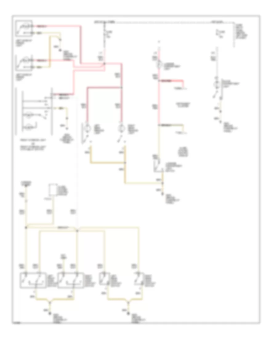
INTERIOR LIGHTS
Courtesy Lamp Wiring Diagram for Volkswagen Golf III 1995
List of elements for Courtesy Lamp Wiring Diagram for Volkswagen Golf III 1995:
- Alarm system control module
- D/3
- Front interior light
- Front interior light with delay switch
- Fuse 15a
- Fuse/ relay panel (behind left side of dash)
- G202 (behind fuse/relay panel)
- Glove compartment light
- Hot at all times
- Hot in on
- Instrument cluster
- L/5
- L/7
- Left front door contact switch
- Left make-up mirror light
- Left rear door contact switch
- Left rear reading light
- Luggage compartment light
- Luggage compartment light switch
- Not used
- Right front door contact switch
- Right rear door contact switch
- Right rear reading light
- T10/10
- T10/5
- T28b/6
- Warning system
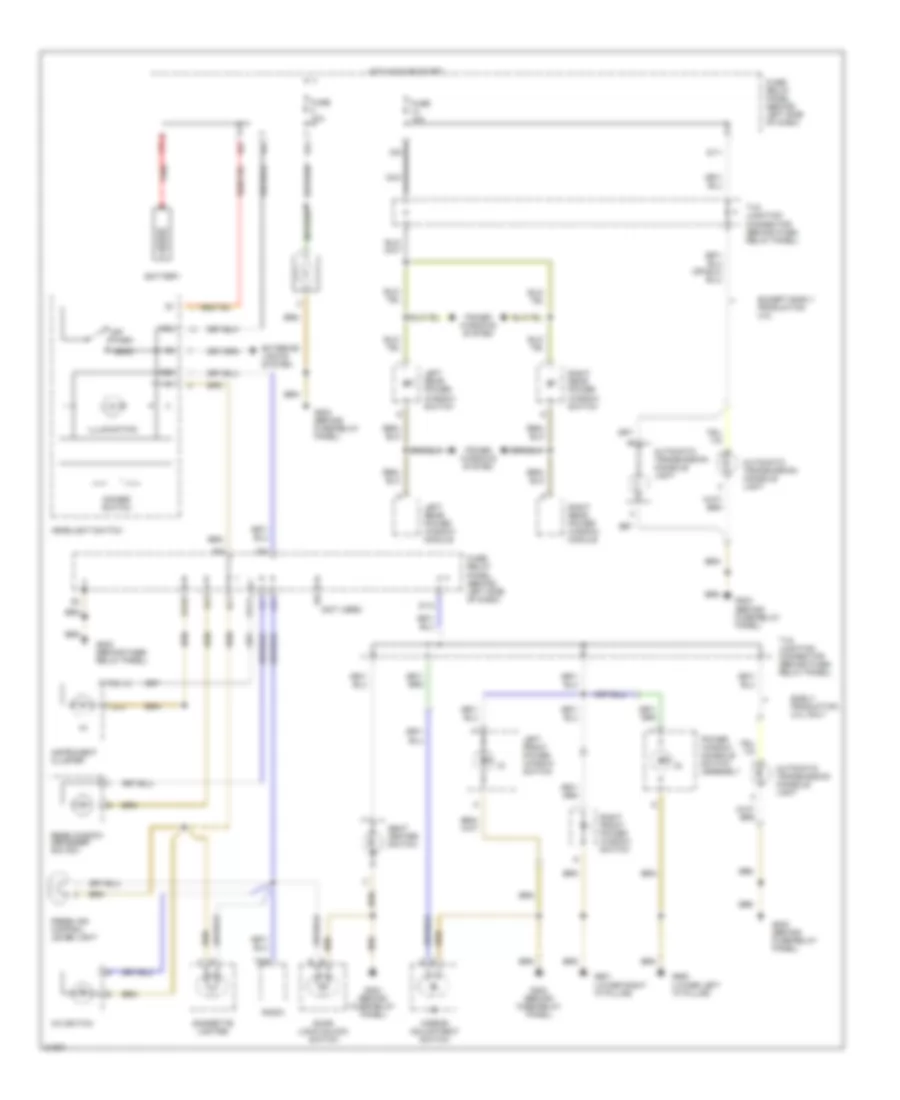
Instrument Illumination Wiring Diagram for Volkswagen Golf III 1995
List of elements for Instrument Illumination Wiring Diagram for Volkswagen Golf III 1995:
- (2)
- (3)
- (4)
- (lower left "a" pillar)
- (lower right "a" pillar)
- (not used)
- 58b
- 58l
- A/c switch
- Automatic transmission console light
- Battery
- Cigarette lighter
- D/11
- D/12
- D/9
- Dimmer switch
- Door lock/unlock switch
- Early production 2.0l only
- Except early production 2.0l
- Exterior lights system
- Fresh air control lever light
- Fuse 10a
- Fuse/ relay panel (behind left side of dash)
- G202 (behind fuse/ relay panel)
- G202 (behind fuse/relay panel)
- G900
- G901
- Head
- Headlight switch
- Hot in on or start
- Illumination
- Instrument cluster
- K/5
- Left front power window switch
- Left rear power window module
- Left rear power window switch
- Mirror adjustment switch
- Nca
- Off
- P/5
- P/7
- P/9
- Park
- Power window console switch assembly
- Power windows system
- Q/1
- Q/6
- R/2
- R/4
- R/5
- R/8
- Radio
- Rear window defogger switch
- Red
- Right front power window switch
- Right rear power window module
- Right rear power window switch
- Seat heater switch
- T28/12
- T28/3
- T8/6
- Tv5 junction connector (behind fuse/ relay panel)
- Tv8 junction connector (behind fuse/ relay panel)
- U1/10
- U1/14
- Y/3
POWER DISTRIBUTION
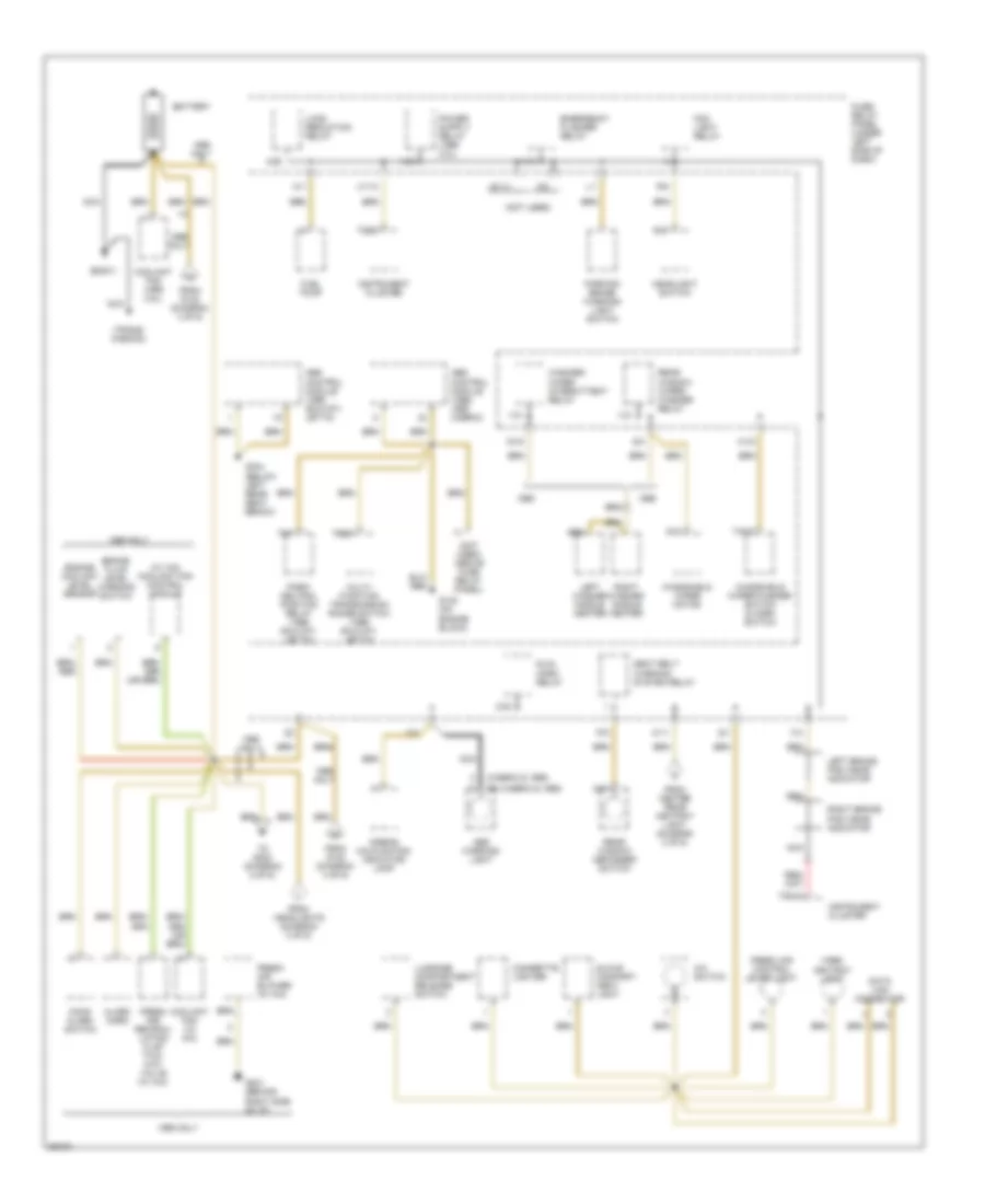
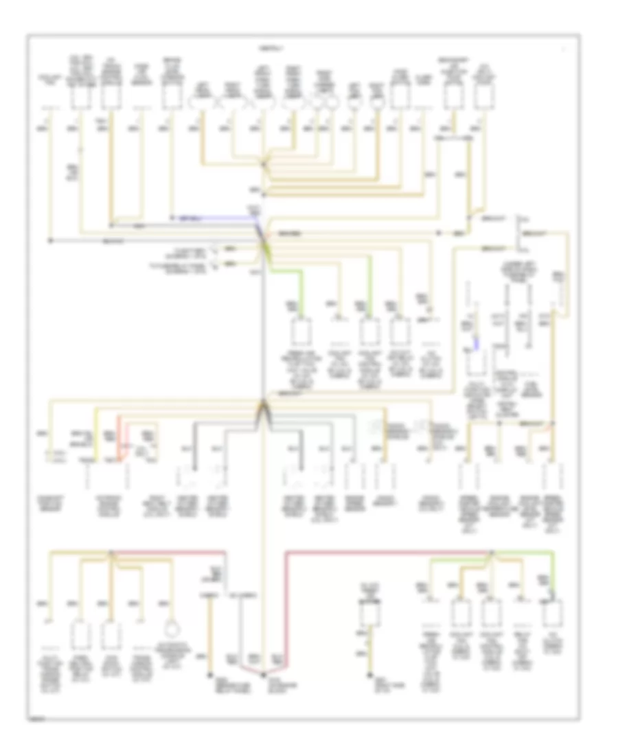
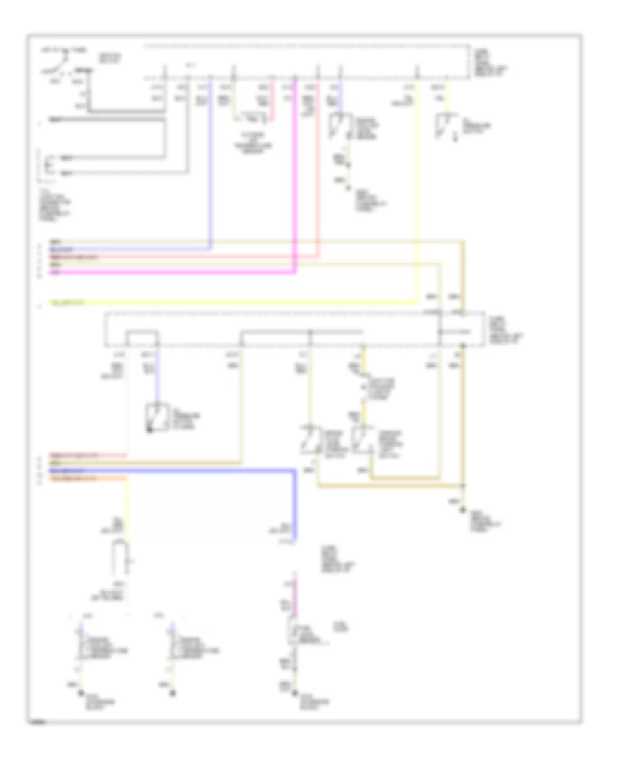
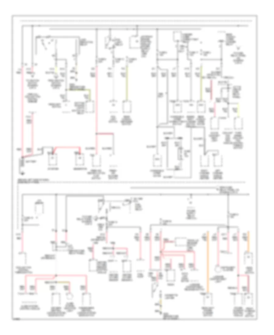
Power Distribution Wiring Diagram (1 of 3) for Volkswagen Golf III 1995
List of elements for Power Distribution Wiring Diagram (1 of 3) for Volkswagen Golf III 1995:
- (1995 2.8l)
- (1995 2.8l) coolant fan control module
- (behind left side of dash) fuse/relay panel
- 0nly
- 15a
- 1995 2.0l
- 1996 & 2.8l
- 2.8l
- 2.8l only
- 3/86
- 4/87
- 53a
- 6/30
- A/c relay
- A1/5
- Alarm system control module
- Alarm system indicator light
- Battery
- Cigarette lighter
- Coolant fan con- trol module
- Coolant fan control thermoswitch
- D/3
- Data link conn- ector
- Daytime running lights switch on relay
- Driver's central locking system door switch
- Emerg- ency flasher switch (1995 2.8l)
- Ex 1995 2.0l
- Ex 2.8l
- Fog light relay
- Fog light switch
- Free air/ recirculation flap switch
- Fresh air blower switch
- From fuse/ relay panel (15) (diagram 2 of 3)
- From ignition switch (diagram 2 0f 3)
- Front interior light switch
- Fuel pump
- Fuel pump relay
- Fuse 10 15a
- Fuse 10a
- Fuse 17 10a
- Fuse 18 20a
- Fuse 19 30a
- Fuse 21 15a
- Fuse 22 10a
- Fuse 4 15a
- Fuse 5 15a
- Fuse 6 30a
- Fuse 9 20a
- G1/8
- G202 (beside fuse relay panel)
- G202 (beside fuse/ relay panel)
- Generator
- Glove compart- ment light
- H1/2
- H1/3
- H1/5
- Head- light switch
- Headlight switch
- Headlight/ dimmer flasher switch
- Heated oxygen sensor
- Heated oxygen sensor 2
- Heated oxygen sensor control module
- Instrument cluster
- J/4
- J/7
- J/c tv2 (behind fuse/ relay panel)
- J/c tv6 (above fuse relay panel)
- K/6
- L/5
- L/7
- Left washer nozzle heater
- Load reduction relay
- Luggage compartment light
- Luggage compartment release switch
- M/2
- P/2
- P/4
- Passenger's central locking system door switch
- Power sunroof control module
- Q/2
- R/10
- R/5
- Radio
- Rear window defogger switch
- Rear window wiper motor
- Rear window wiper/ washer relay
- Red
- Right washer nozzle heater
- S/1
- Starter
- T/1
- T10/1
- T10a/9
- T28/11
- T4c/4
- T4i/4
- T5c/2
- T6/3
- T6a/5
- T8/2
- T8/7
- Tb5/5
- Third speed coolant fan control thermal switch
- To fuse/ relay panel (30) (diagram 3 of 3)
- To fuse/ relay panel (diagram 3 of 3)
- To ignition switch (diagram 2 0f 3)
- Trunk lid release switch (1996 only)
- U2/11
- Washer/ wiper intermittent relay
- Windshield wiper intermittent switch
- Windshield wiper motor
- Y/3
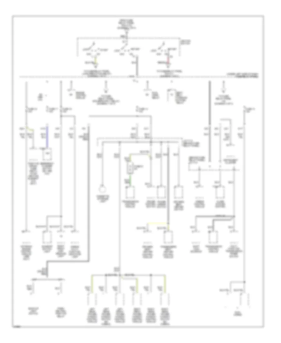
Power Distribution Wiring Diagram (2 of 3) for Volkswagen Golf III 1995
List of elements for Power Distribution Wiring Diagram (2 of 3) for Volkswagen Golf III 1995:
- (behind fuse/ relay panel) j/c tv4
- (under left side of dash) fuse/relay panel)
- 15a
- A/t
- A1/7
- Acc
- Airbag control module
- Airbag multi- function indicator lamp
- Alarm system control
- Back-up light switch
- Cassette storage light
- Cruise control switch
- D/11
- D/8
- D/9
- Driver's seat heater control module
- Driver's seat heater switch
- Dual horn relay
- Dual horns
- E/2
- Emergency flasher switch (ex 1995 2.8l)
- Engine control module
- Ex 2.8l
- F/6
- From fuse/ relay panel (pin h1/2) (diagram 1 of 3)
- Fuse 13 15a
- Fuse 14 10a
- Fuse 15 10a
- Fuse 16 15a
- Fuse 17 10a
- Fuse 51 5a
- G2/4
- H1/4
- H1/5
- Ignition switch
- Instrument cluster
- J/c tv 5 (behind fuse/ relay panel)
- Left front power window control module
- Left rear power window control module
- Left rear power window switch (ex cabrio)
- Lock
- M/5
- M/t
- Module
- Motronic engine control module (1996 only)
- Multi- function transmission range switch
- Park/ neutral position relay
- Passenger's seat heater control module
- Positive crank- case ventil- ation heating element (2.8l only)
- Power mirror switch
- Red
- Right front map/ reading light
- Right front power window control module
- Right rear power window control module
- Right rear power window switch (ex cabrio)
- Seat belt warning system relay
- Shift lock solenoid
- Start
- Sunroof switch light
- T10/4
- T4c/4
- To fuse/ relay panel (15) (diagram 3 of 3)
- To fuse/relay panel (load reduction relay) (diagram 1 of 3)
- To fuse/relay panel pin h1/1 (diagram 3 of 3)
- Transmission control module
- U2/1
- X/4
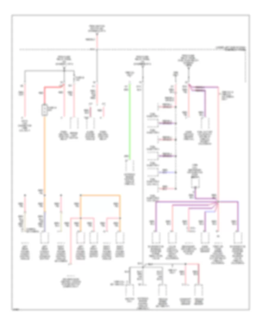
Power Distribution Wiring Diagram (3 of 3) for Volkswagen Golf III 1995
List of elements for Power Distribution Wiring Diagram (3 of 3) for Volkswagen Golf III 1995:
- (1995 2.8l) (ex 1995 2.8l)
- (1996 2.8l) secondary air injection pump relay
- (2.0l)
- (2.8l)
- (cabrio) (ex cabrio)
- (under left side of dash) fuse/relay panel
- 1996 2.8l & 1996 2.0l california only
- 1996 2.8l only
- 1996 a/t only
- A/t
- Alarm system control module
- Brake light switch
- Camshaft position sensor
- Data link connector (1996 2.8l only)
- Driver's door central locking system switch (cabrio only)
- E/4
- Evaporative emission canister purge regulator valve
- Evaporative emission canister purge solenoid valve (1996 2.0l california)
- F/1
- First or third speed coolant fan control cut-off relay (1996 2.0l california)
- From fuse/ relay panel (15) (diagram 2 of 3)
- From fuse/ relay panel (30) (diagram 1 of 3)
- From fuse/ relay panel (fuel pump relay) (diagram 1 of 3)
- From ignition switch (50) (diagram 2 of 3)
- Fuel cut-off valve shut- off relay (1996 2.0l except california)
- Fuel injector 1
- Fuel injector 2
- Fuel injector 3
- Fuel injector 4
- Fuel injector 5 (2.8l only)
- Fuel injector 6 (2.8l only)
- Fuse 20 10a
- Fuse 43 20a
- G1/4
- G2/8
- H1/1
- Ignition coil
- Left front power window control module
- Left front power window switch
- Left rear power window control module
- Left rear window switch (console switch)
- M/t
- Mass air flow sensor
- Mass air flow sensor (1995 2.8l)
- Motronic engine control module (1995 only)
- Motronic engine control module (1996 2.8l)
- N/1
- Only
- Park/ neutral position relay
- Red
- Right front power window control module
- Right front power window switch
- Right rear power window control module (ex cabrio)
- Secondary air injection solenoid valve
- T6/5
- Valve for full throttle impact (1996 2.0l california)
- Vehicle speed sensor
- Vehicle speed sensor (ex 1996 a/t)
- Y/2
- Z/1
POWER DOOR LOCKS
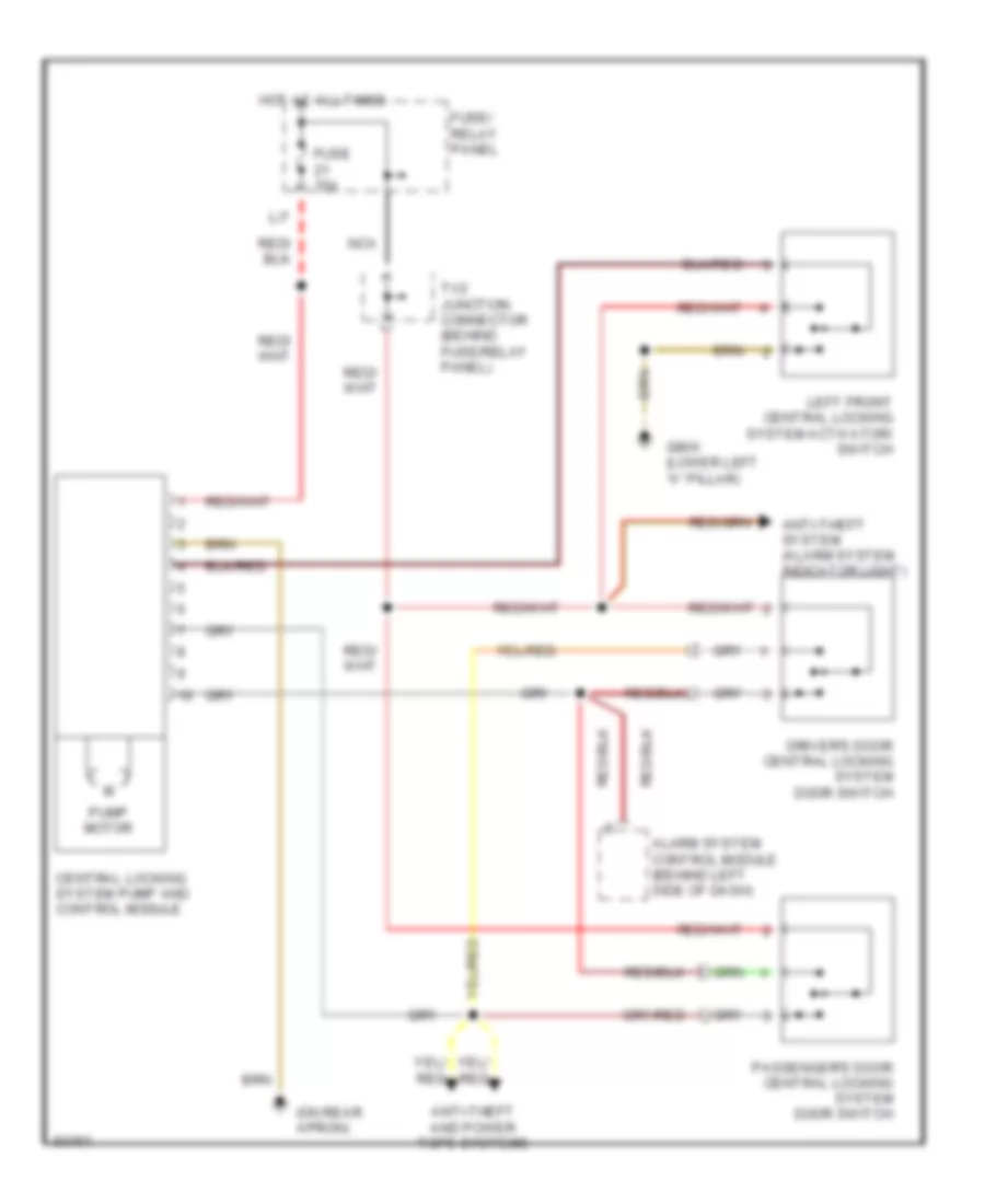
Power Door Lock Wiring Diagram for Volkswagen Golf III 1995
List of elements for Power Door Lock Wiring Diagram for Volkswagen Golf III 1995:
- (on rear apron)
- Alarm system control module (behind left side of dash)
- Anti-theft and power tops systems
- Anti-theft system (alarm system indicator light)
- Central locking system pump and control module
- Driver's door central locking system door switch
- Fuse 15a
- Fuse/ relay panel
- G900 (lower left "a" pillar)
- Hot at all times
- L/7
- Left front central locking system activator/ switch
- Nca
- Passenger's door central locking system door switch
- Pump motor
- Tv2 junction connector (behind fuse/relay panel)
POWER MIRRORS
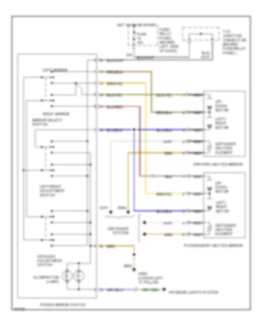
Power Mirror Wiring Diagram for Volkswagen Golf III 1995
List of elements for Power Mirror Wiring Diagram for Volkswagen Golf III 1995:
- D/9
- Defogger heating element
- Defogger system
- Driver's heated mirror
- Fuse 10a
- Fuse/ relay panel (behind left side of dash)
- G900 (lower left "a" pillar)
- Hot in on or start
- Illumination lamps
- Interior lights system
- Left mirror
- Left/ right motor
- Left/right adjustment switch
- Mirror select switch
- Nca
- Passenger's heated mirror
- Power mirror switch
- Right mirror
- Tv5 junction connector (behind fuse/relay panel)
- Up/ down motor
- Up/down adjustment switch
POWER SEATS
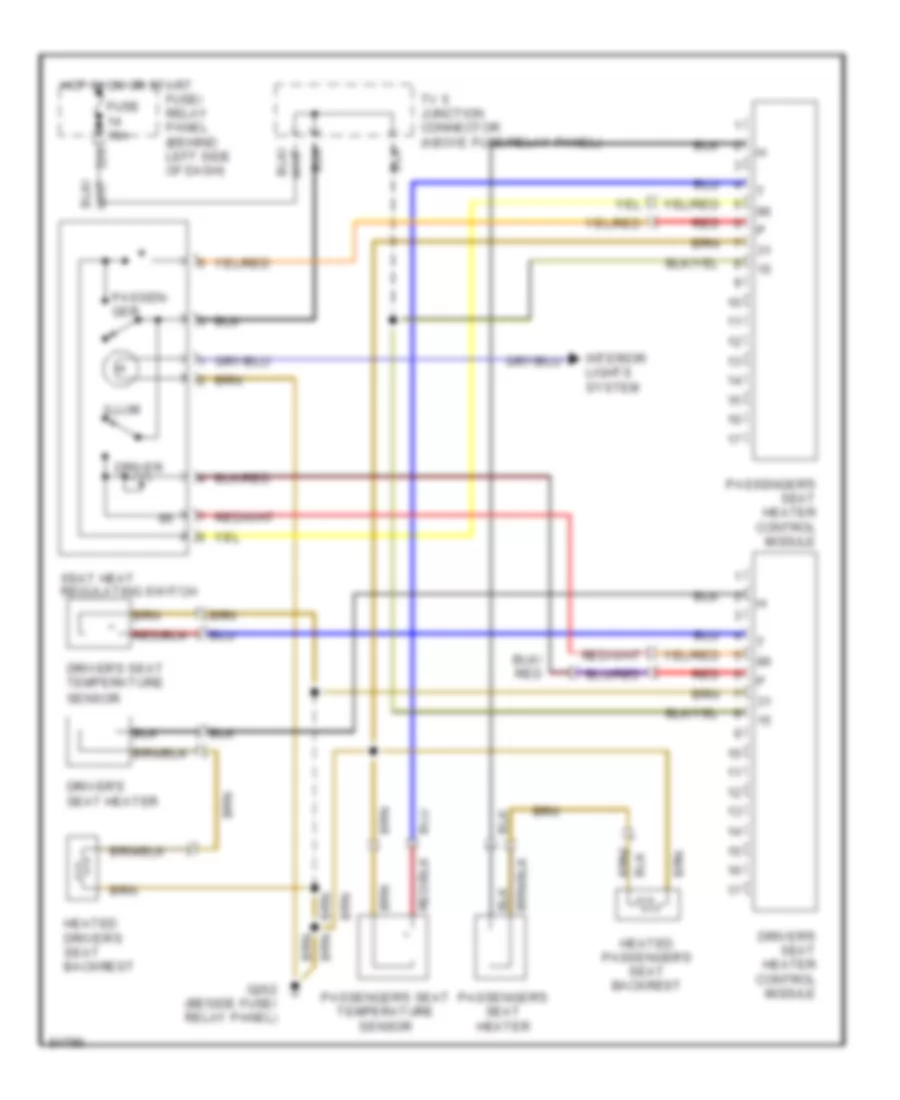
Heated Seats Wiring Diagram for Volkswagen Golf III 1995
List of elements for Heated Seats Wiring Diagram for Volkswagen Golf III 1995:
- D/9
- Driver
- Driver's seat heater
- Driver's seat heater control module
- Driver's seat temperature sensor
- Fuse 10a
- Fuse/ relay panel (behind left side of dash)
- G202 (beside fuse/ relay panel)
- Heated driver's seat backrest
- Heated passenger's seat backrest
- Hot in on or start
- Illum
- Interior lights system
- Passen- ger
- Passenger's seat heater
- Passenger's seat heater control module
- Passenger's seat temperature sensor
- Red
- Seat heat regulating switch
- Tv 5 junction connector (above fuse/relay panel)
POWER TOP/SUNROOF
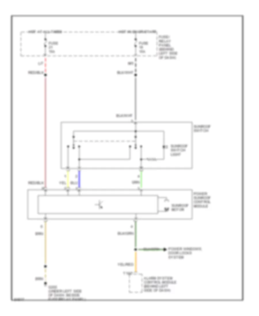
Sunroof Wiring Diagram for Volkswagen Golf III 1995
List of elements for Sunroof Wiring Diagram for Volkswagen Golf III 1995:
- Alarm system control module (behind left side of dash)
- Fuse 15a
- Fuse/ relay panel (behind left side of dash)
- G202 (under left side of dash. beside fuse/relay panel)
- Hot at all times
- Hot in on or start
- L/7
- M/5
- Power sunroof control module
- Power windows, door locks system
- Sunroof motor
- Sunroof switch
- Sunroof switch light
- T10/7
POWER WINDOWS
Power Window Wiring Diagram (1 of 2) for Volkswagen Golf III 1995
List of elements for Power Window Wiring Diagram (1 of 2) for Volkswagen Golf III 1995:
- (not used)
- Anti-theft system
- D/9
- Driver's power window switch assembly
- Fuse 10a
- Fuse 20a
- Fuse/ relay panel
- G202 (behind fuse/ relay panel)
- G900 (lower left "a" pillar)
- G901 (lower right "a" pillar)
- Hot at all times
- Hot in run or start
- Illumination
- Illumination (2)
- Interior lights system (headlight switch)
- Left front door contact switch
- Left front power window control module
- Left front window switch
- Nca
- Power window inline fuse
- Red
- Right front power window control module
- Right front power window switch
- Right front window switch
- T1a
- T1d
- Tv5 junction connector (behind fuse/relay panel)
- Window motor
- Y/2
Power Window Wiring Diagram (2 of 2) for Volkswagen Golf III 1995
List of elements for Power Window Wiring Diagram (2 of 2) for Volkswagen Golf III 1995:
- G305 (near right "b" pillar)
- Illumination
- Illumination (3)
- Information not available
- Interior lights system
- Left front window switch
- Left rear power window control module
- Left rear window switch
- Nca
- Power window console switch assembly
- Right rear power window control module
- Right rear power window switch
- Right rear window switch
- T21/20
- T21a/20
- Window lockout switch
- Window motor
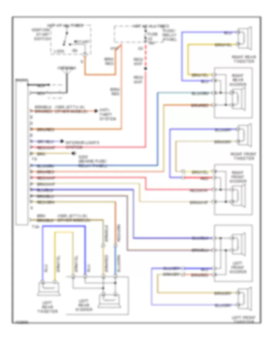
RADIO
Radio Wiring Diagrams for Volkswagen Golf III 1995
List of elements for Radio Wiring Diagrams for Volkswagen Golf III 1995:
- (1995 jetta iii) (other models)
- Antenna
- Anti- theft system
- Fuse 10a
- Fuse/ relay panel
- G202 (behind fuse/ relay panel)
- H1/7
- Hot at all times
- Ignition/ start switch
- Interior lights system
- Left front tweeter
- Left front woofer
- Left rear tweeter
- Left rear woofer
- Lock
- Nca
- Radio
- Red
- Right front tweeter
- Right front woofer
- Right rear tweeter
- Right rear woofer
- Start
- Tga
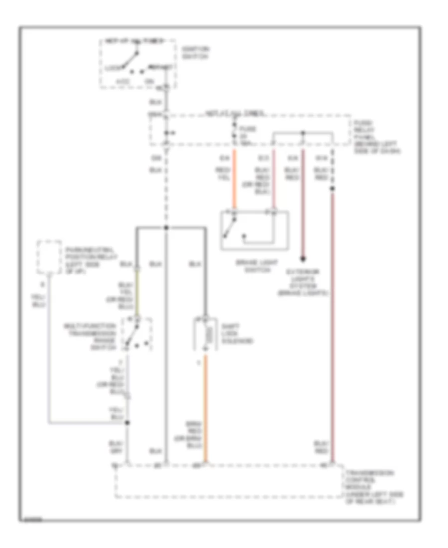
SHIFT INTERLOCKS
Shift Interlock Wiring Diagram for Volkswagen Golf III 1995
List of elements for Shift Interlock Wiring Diagram for Volkswagen Golf III 1995:
- Acc
- Brake light switch
- D/8
- E/3
- E/4
- Exterior lights system (brake lights)
- Fuse 10a
- Fuse/ relay panel (behind left side of dash)
- H1/4
- Hot at all times
- Ignition switch
- K/4
- Lock
- Multi-function transmission range switch
- Park/neutral position relay (left side of i/p)
- Shift lock solenoid
- Start
- Transmission control module (under left side of rear seat)
- W/4
STARTING/CHARGING
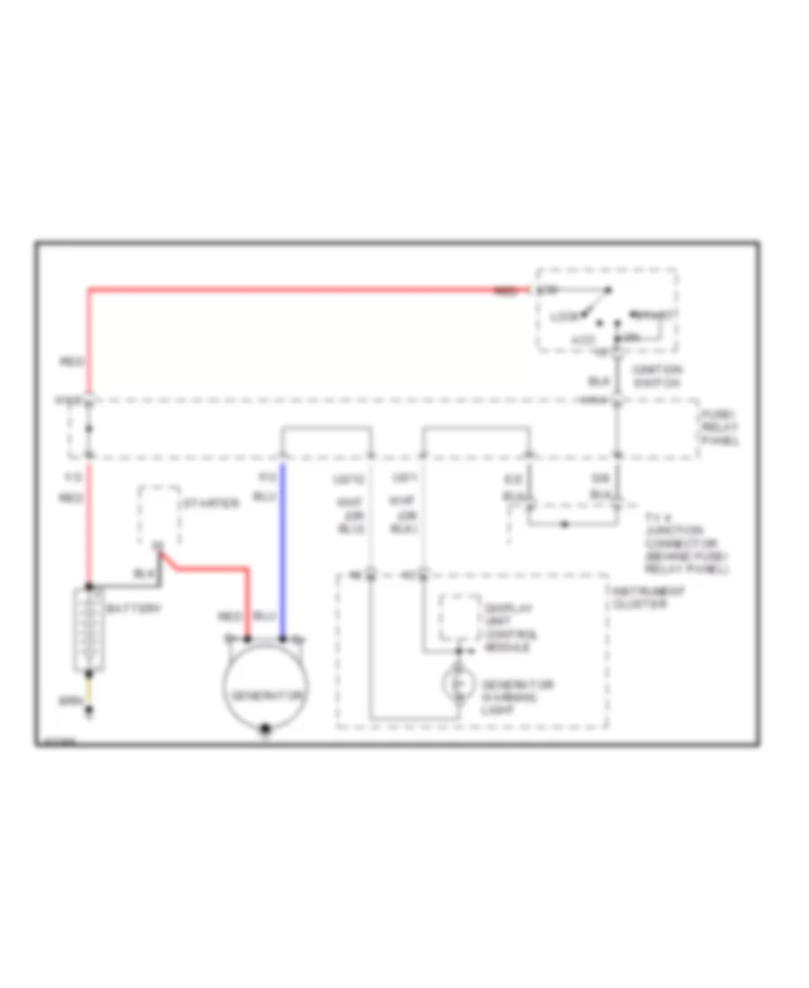
Charging Wiring Diagram for Volkswagen Golf III 1995
List of elements for Charging Wiring Diagram for Volkswagen Golf III 1995:
- Acc
- Battery
- D/8
- Display unit control module
- E/2
- F/3
- Fuse/ relay panel
- Generator
- Generator warning light
- H1/2
- H1/4
- Ignition switch
- Instrument cluster
- Lock
- Red
- Start
- Starter
- Tv 4 junction connector (behind fuse/ relay panel)
- U2/1
- U2/12
- Y/3
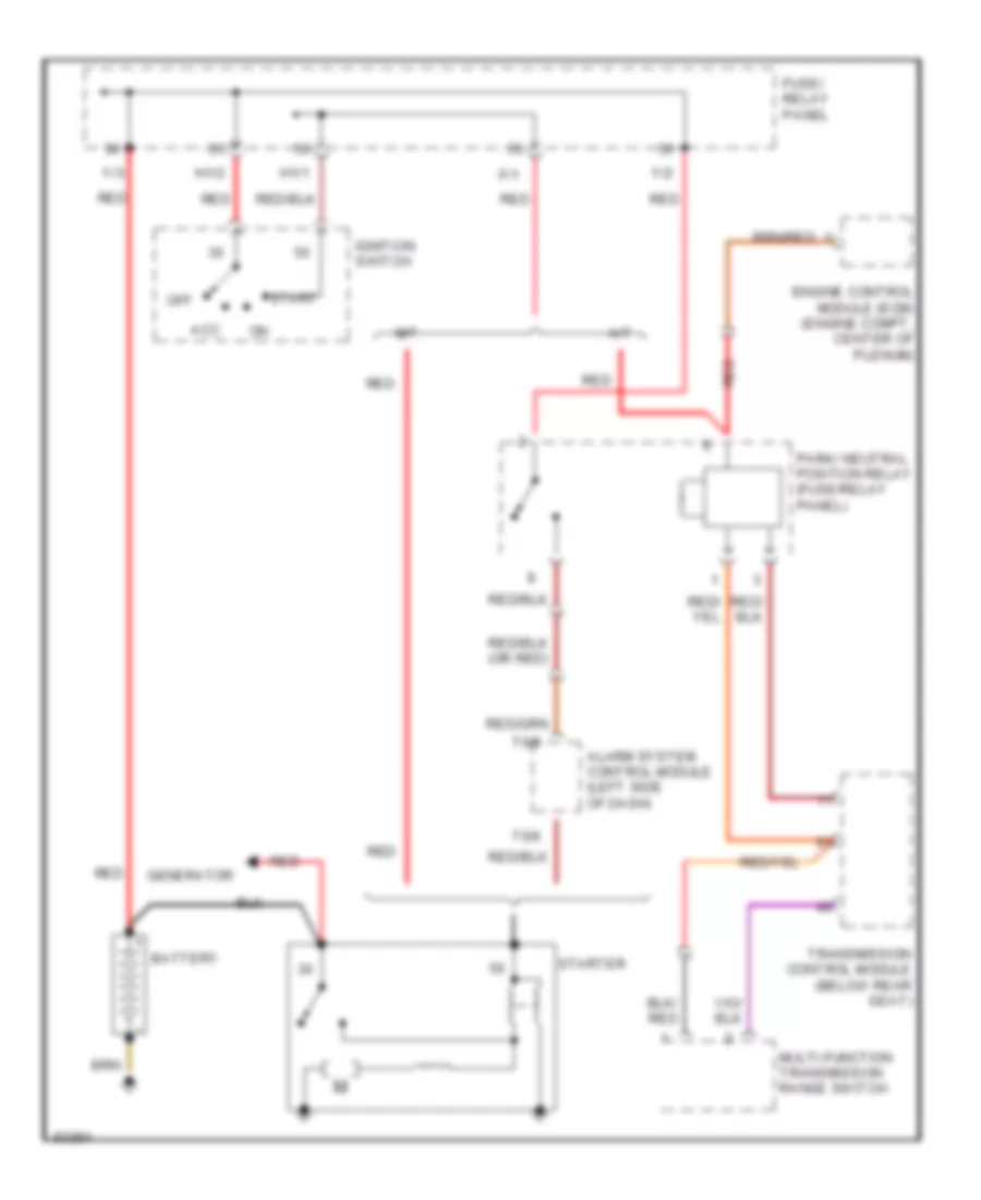
Starting Wiring Diagram, Early Production for Volkswagen Golf III 1995
List of elements for Starting Wiring Diagram, Early Production for Volkswagen Golf III 1995:
- A/t
- Acc
- Alarm system control module (left side of dash)
- Battery
- Engine control module (ecm) (engine compt, center of plenum)
- F/1
- Fuse/ relay panel
- Generator
- H1/1
- H1/2
- Ignition switch
- M/t
- Multi-function transmission range switch
- Off
- Park/ neutral position relay (fuse/relay panel)
- Red
- Start
- Starter
- T6/5
- T6/6
- Transmission control module (below rear seat)
- Y/2
- Y/3
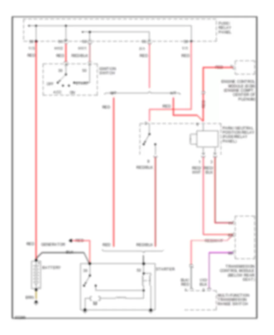
Starting Wiring Diagram, Late Production for Volkswagen Golf III 1995
List of elements for Starting Wiring Diagram, Late Production for Volkswagen Golf III 1995:
- A/t
- Acc
- Battery
- Engine control module (ecm) (engine compt, center of plenum)
- F/1
- Fuse/ relay panel
- Generator
- H1/1
- H1/2
- Ignition switch
- M/t
- Multi-function transmission range switch
- Off
- Park/ neutral position relay (fuse/relay panel)
- Red
- Start
- Starter
- Transmission control module (below rear seat)
- Y/1
- Y/3
SUPPLEMENTAL RESTRAINTS
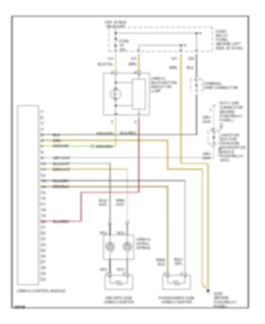
Supplemental Restraint Wiring Diagram for Volkswagen Golf III 1995
List of elements for Supplemental Restraint Wiring Diagram for Volkswagen Golf III 1995:
- Airbag control module
- Airbag malfunction indicator lamp
- Airbag spiral spring
- D/8
- Data link connector (behind fuse/relay panel)
- Driver's side airbag igniter
- Fuse 15a
- Fuse/ relay panel (behind left side of dash)
- G202 (behind fuse/relay panel)
- Hot in run or start
- Nca
- Passenger's side airbag igniter
- Q/1
- Tb2 junction box for on board diagnostics (above fuse/relay t2hh box)
- Terminal wire connector
- X/2
- X/4
TRANSMISSION
2.0L
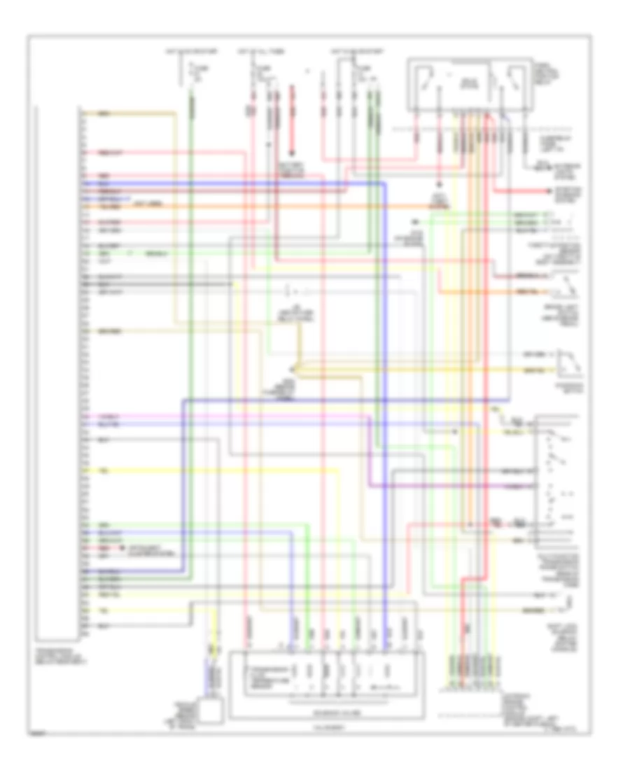
2.0L, Transmission Wiring Diagram, Early Production for Volkswagen Golf III 1995
List of elements for 2.0L, Transmission Wiring Diagram, Early Production for Volkswagen Golf III 1995:
- (not used)
- 1995 vftc c
- Anti- theft system
- Battery positive terminal
- Brake light switch (above brake pedal)
- D/8
- E/3
- E/4
- Exterior lights system
- F/6
- F/9
- Fuse 10a
- Fuse 5a
- Fuse/relay panel (left i/p)
- G1/12
- G132 (on engine block)
- G202 (beside fuse/relay panel)
- Hot at all times
- Hot in on or start
- Instrument cluster system
- J/b (above fuse/ relay panel)
- Kick-down switch
- Motronic engine control module (engine compt, left of center plenum)
- Multi-function transmission range switch (rear of transmission case)
- Park/ neutral position relay
- Red
- Shift lock solenoid (below shifter console)
- Solenoid valves
- Solid state
- Starting/ charging system
- Throttle position sensor (on throttle body assembly)
- Transmission control module (below rear seat)
- Transmission fluid temperature sensor
- Valve body
- Vehicle speed sensor (left front of trans)
- W/4
- Y/2
- Y/3
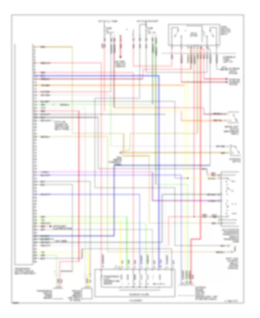
2.0L, Transmission Wiring Diagram, Late Production for Volkswagen Golf III 1995
List of elements for 2.0L, Transmission Wiring Diagram, Late Production for Volkswagen Golf III 1995:
- (not used)
- 1995 vftc c
- Battery positive terminal
- Brake light switch (above brake pedal)
- D/8
- Data link connector (above fuse/ relay panel)
- E/3
- E/4
- Exterior lights system
- F/6
- F/9
- Fuse 10a
- Fuse/relay panel (left i/p)
- G1/12
- G202 (beside fuse/relay panel)
- Hot at all times
- Hot in on or start
- Instrument cluster system
- Kick-down switch
- Motronic engine control module (engine compt, left of center plenum)
- Multi-function transmission range switch (rear of transmission case)
- Park/ neutral position relay
- Red
- Shift lock solenoid (below shifter console)
- Solenoid valves
- Solid state
- Starting/ charging system
- Transmission control module (below rear seat)
- Transmission fluid temperature sensor
- Transmission vehicle speed sensor
- Valve body
- Vehicle speed sensor (left front of trans)
- W/4
- Y/1
- Y/2
TRUNK, TAILGATE, FUEL DOOR
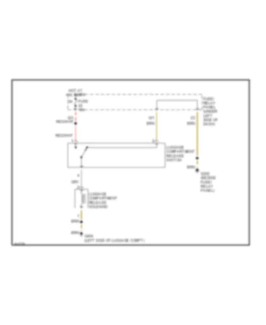
Trunk Release Wiring Diagram for Volkswagen Golf III 1995
List of elements for Trunk Release Wiring Diagram for Volkswagen Golf III 1995:
- Fuse 10a
- Fuse/ relay panel (under left side of dash)
- G202 (beside fuse/ relay panel)
- G404 (left side of luggage compt)
- Hot at all times
- Luggage compartment release solenoid
- Luggage compartment release switch
- Q/1
WARNING SYSTEMS
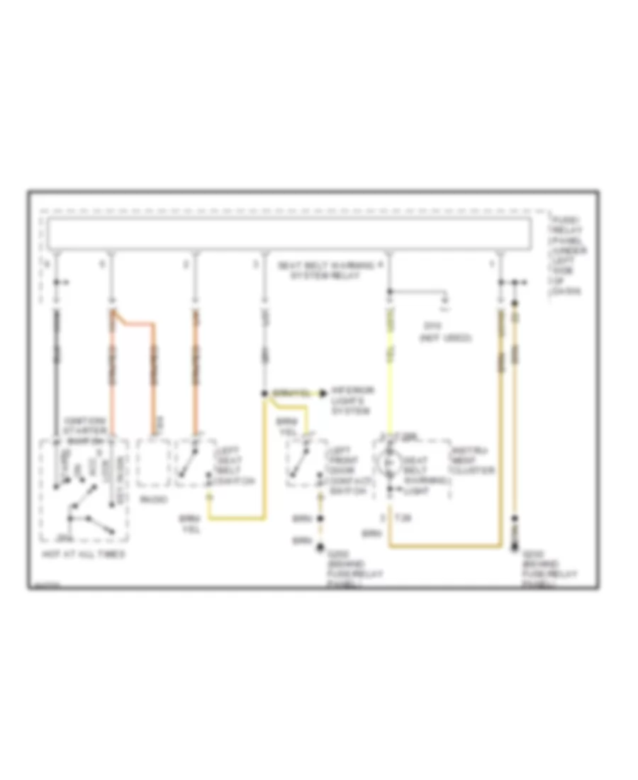
Warning System Wiring Diagrams for Volkswagen Golf III 1995
List of elements for Warning System Wiring Diagrams for Volkswagen Golf III 1995:
- (not used)
- Acc
- D10
- Fuse/ relay panel (under left side of dash)
- G202 (behind fuse/relay panel)
- H1/4
- H1/7
- Hot at all times
- Ignition/ starter switch
- Instru- ment cluster
- Interior lights system
- Key in ign
- L/2
- L/4
- Left front door contact switch
- Left seat belt switch
- Lock
- Radio
- Seat belt warning light
- Seat belt warning system relay
- Start
- T28
- T28b
- T8/4
- U1/10
- U2/3
WIPER/WASHER
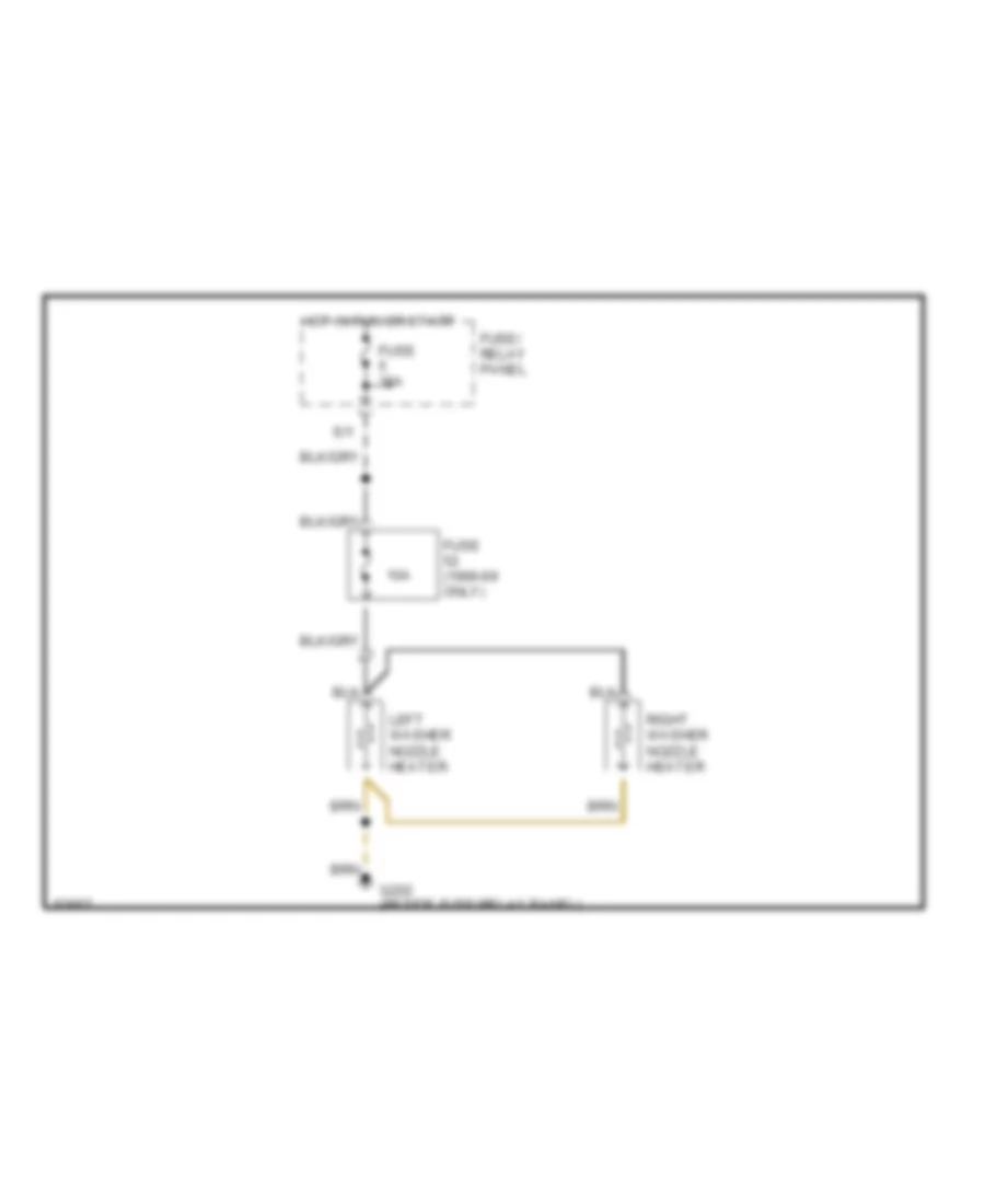
Heated Windshield Washer Wiring Diagram for Volkswagen Golf III 1995
List of elements for Heated Windshield Washer Wiring Diagram for Volkswagen Golf III 1995:
- 10a
- Fuse (1996-99 only)
- Fuse 15a
- Fuse/ relay panel
- G202 (beside fuse/relay panel)
- Hot in run or start
- Left washer nozzle heater
- Right washer nozzle heater
- S/1
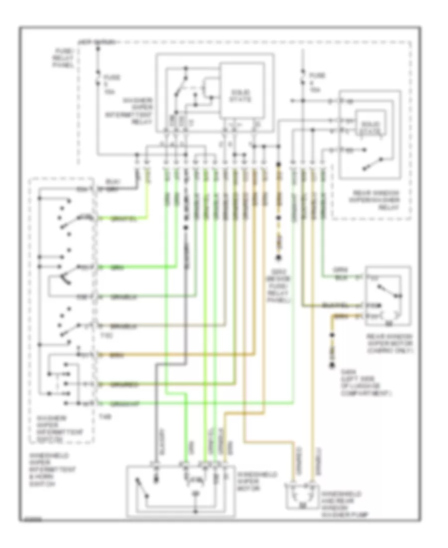
Wiper/Washer Wiring Diagram for Volkswagen Golf III 1995
List of elements for Wiper/Washer Wiring Diagram for Volkswagen Golf III 1995:
- 53a
- 53b
- 53b 53e
- 53e
- 53m
- 53s
- C/2
- C/7
- Fuse 15a
- Fuse/ relay panel
- G202 (beside fuse/ relay panel)
- G404 (left side of luggage compartment)
- H1/6
- H1/8
- H1/9
- Hot in run
- J/10
- J/5
- J/6
- J/7
- J/9
- K/6
- K/9
- Rear window wiper motor (cabrio only)
- Rear window wiper/washer relay
- S/1
- S/2
- S/3
- S/4
- S/5
- Solid state
- T4b
- T5c
- Washer/ wiper intermittent relay
- Washer/ wiper intermittent switch
- Windshield and rear window washer pump
- Windshield wiper intermittent & horn switch
- Windshield wiper motor
- Z/2

 Čeština
 Dansk
Dansk Deutsch
 Ελληνικά
 English
 English
 Español
 Suomi
Suomi Français
 Français
 עברית
עברית Hrvatski
 Magyar
 日本語
日本語 한국어
한국어 Nederlands
 Polski
 Português
 Português
 Română
 Русский
 Slovenčina
 Slovenščina
 Svenska
 Türkçe
 中文 (中国)