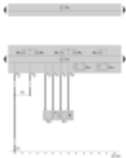
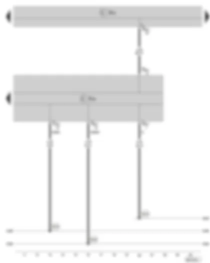
| G182 | Gearbox input speed sender |
| G193 | Hydraulic pressure sender 1 for automatic gearbox |
| G194 | Hydraulic pressure sender 2 for automatic gearbox |
| G509 | Coupling temperature sender |
| J519 | Vehicle voltage control unit |
| J743 | Double clutch gearbox mechatronics |
| N88 | Solenoid valve 1 |
| N89 | Solenoid valve 2 |
| N90 | Solenoid valve 3 |
| N91 | Solenoid valve 4 |
| N92 | Solenoid valve 5 |
| T4bg | 4-pin connector, at the double clutch gearbox mechatronics |
| T20j | 20-pin connector, on automatic gearbox |
| 386 | Earth connection 21 in main wiring harness |
| 607 | Earth point on left in plenum chamber |
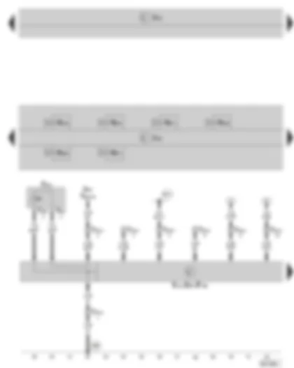
| E313 | Selector lever |
| F189 | Tiptronic switch |
| F319 | Selector lever locked in position P switch |
| J519 | Vehicle voltage control unit |
| J527 | Steering column electronics control unit |
| J587 | Selector lever sensors control unit |
| J743 | Double clutch gearbox mechatronics |
| N215 | Automatic gearbox pressure regulating valve 1 |
| N216 | Automatic gearbox pressure regulating valve 2 |
| N217 | Automatic gearbox pressure regulating valve 3 |
| N218 | Automatic gearbox pressure regulating valve 4 |
| N233 | Automatic gearbox pressure regulating valve 5 |
| N371 | Automatic gearbox pressure regulating valve 6 |
| T4bf | 4-pin connector, at selector lever |
| T10m | 10-pin connector, at selector lever |
| T20a | 20-pin connector, at steering column electronics control unit |
| 688 | Earth point 2 on the middle tunnel |
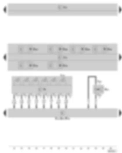
| B341 | Connection 2 (58d) in main wiring harness |
| E313 | Selector lever |
| F189 | Tiptronic switch |
| G195 | Gearbox output speed sender |
| G196 | Gearbox output speed sender 2 |
| G487 | Path sensor 1 for gear actuator |
| G488 | Path sensor 2 for gear actuator |
| G489 | Path sensor 3 for gear actuator |
| G490 | Path sensor 4 for gear actuator |
| J519 | Vehicle voltage control unit |
| J587 | Selector lever sensors control unit |
| J743 | Double clutch gearbox mechatronics |
| L101 | Bulb for selector lever display illumination |
| N110 | Selector lever lock magnet |
| T4bf | 4-pin connector, at selector lever |
| T10n | 10-pin plug connection, at the selector lever position indicator |
| Y6 | Selector lever position indicator |
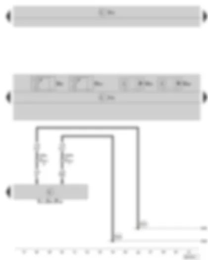
| E313 | Selector lever |
| F189 | Tiptronic switch |
| G93 | Gearbox oil temperature sender |
| G501 | Drive shaft speed sender 1 |
| G502 | Drive shaft speed sender 2 |
| G510 | Temperature sender in control unit |
| J519 | Vehicle voltage control unit |
| J587 | Selector lever sensors control unit |
| J743 | Double clutch gearbox mechatronics |
| T10m | 10-pin connector, at selector lever |
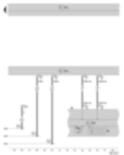
| B383 | Connection 1 (drive train CAN bus High) in main wiring harness |
| B390 | Connection 1 (drive train CAN bus Low) in main wiring harness |
| J519 | Vehicle voltage control unit |
| J743 | Double clutch gearbox mechatronics |
| T20j | 20-pin connector, on automatic gearbox |
| T52c | 52-pin connector, at onboard supply control unit (brown) |
| B383 | Connection 1 (drive train CAN bus High) in main wiring harness |
| B390 | Connection 1 (drive train CAN bus Low) in main wiring harness |
| B625 | Connection (diagnosis wire K), in main wiring harness |
| J285 | Control unit in dash panel insert |
| J519 | Vehicle voltage control unit |
| J533 | Data bus diagnostic interface |
| K | Dash panel insert |
| K169 | Selector lever lock warning light |
| T16b | 16-pin connector, for diagnostic connection, below the left dash panel |
| T20c | 20-pin connector, at data bus diagnostic interface |
| T32a | 32-pin connector, at dash panel insert |
| Y6 | Selector lever position indicator |
| B383 | Connection 1 (drive train CAN bus High) in main wiring harness |
| B390 | Connection 1 (drive train CAN bus Low) in main wiring harness |
| B625 | Connection (diagnosis wire K), in main wiring harness |

 Deutsch
 English
 English
 Español
 Français
 Nederlands
 Русский

