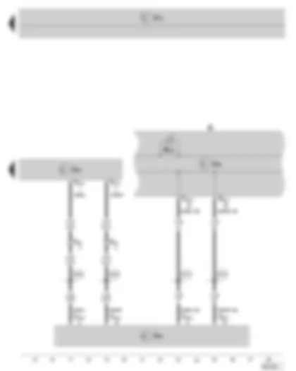
| G85 | Steering angle sender |
| G269 | Steering moment sender |
| J500 | Power steering control unit |
| J519 | Vehicle voltage control unit |
| SA2 | Fuse 2 on fuse holder A |
| SC6 | Fuse 6 on fuse holder C |
| T2g | 2-pin connector, at power steering control unit |
| T3m | 3-pin connector, at power steering control unit |
| T5g | 5-pin connector, at power steering control unit |
| T6j | 6-pin connector, on front left in engine compartment (black) |
| V187 | Electro/mechanical power steering motor |
| 12 | Earth point on left in engine compartment |
| B278 | Positive connection 2 (15a) in main wiring harness |
| J285 | Control unit in dash panel insert |
| J500 | Power steering control unit |
| J519 | Vehicle voltage control unit |
| J533 | Data bus diagnostic interface |
| K | Dash panel insert |
| K161 | Electro/mechanical power steering warning light |
| T3m | 3-pin connector, at power steering control unit |
| T6j | 6-pin connector, on front left in engine compartment (black) |
| T20c | 20-pin connector, at data bus diagnostic interface |
| T32a | 32-pin connector, at dash panel insert |
| B383 | Connection 1 (drive train CAN bus High) in main wiring harness |
| B390 | Connection 1 (drive train CAN bus Low) in main wiring harness |
| B708 | Connection 1 (CAN bus dash panel insert High) in main wiring harness |
| B709 | Connection 1 (CAN bus dash panel insert Low) in main wiring harness |

 Deutsch
 English
 English
 Español
 Français
 Nederlands
 Русский

