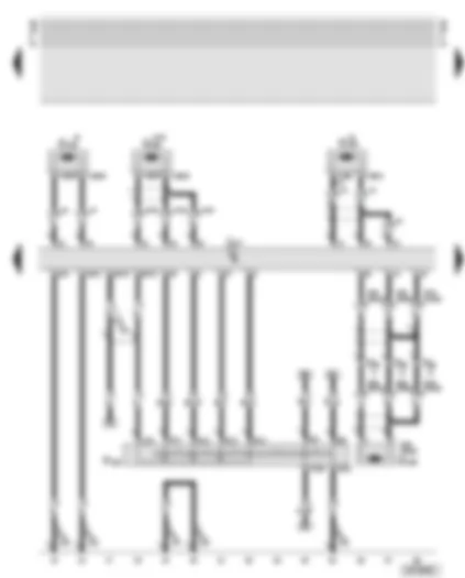
| G93 | Oil temperature sender |
| J217 | Automatic gearbox control unit |
| N88 | Solenoid valve 1 |
| N89 | Solenoid valve 2 |
| N90 | Solenoid valve 3 |
| N91 | Solenoid valve 4 |
| N92 | Solenoid valve 5 |
| N93 | Solenoid valve 6 |
| N94 | Solenoid valve 7 |
| N215 | Automatic gearbox pressure control valve -1- |
| N216 | Automatic gearbox pressure control valve -2- |
| N217 | Automatic gearbox pressure control valve -3- |
| N218 | Automatic gearbox pressure control valve -4- |
| N233 | Automatic gearbox pressure control valve -5- |
| T16a | 16-pin connector, diagnosis connection |
| T16b | 16-pin connector, on gearbox |
| T17m | 17-pin connector, blue, connector point, A pillar, right |
| A32 | Positive (+) connection (30), in dash panel wiring harness |
| A76 | Connection (diagnosis wire K), in dash panel wiring harness |
| * | Applies to gearbox 01V only |
| ** | Applies to gearbox 01L only |
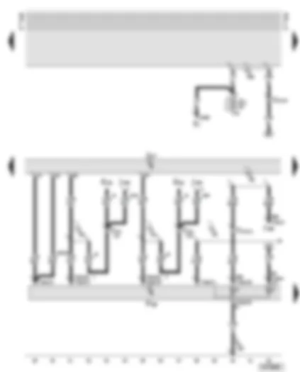
| F125 | Multi-function switch |
| G182 | Gearbox input speed sender |
| G195 | Gearbox output speed sender |
| J217 | Automatic gearbox control unit |
| T3bi | 3-pin connector, black, near gearbox |
| T16b | 16-pin connector, on gearbox |
| 43 | Earth point, lower part of right A pillar |
| 102 | Earth connection, in gearbox wiring harness |
| U2 | Connection -1- (15), in automatic gearbox wiring harness |
| * | Applies to gearbox 01V only |
| ** | Applies to gearbox 01L only |
| *** | Applies to S6 and RS6 models only |
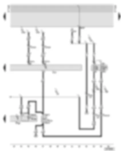
| E1 | Lighting switch |
| E221 | Operating unit in steering wheel |
| F189 | Tiptronic switch |
| J217 | Automatic gearbox control unit |
| J285 | Control unit with display in dash panel insert |
| J453 | Multi-function steering wheel control unit |
| S3 | Fuse in fuse box |
| T10am | 10-pin connector, on selector lever console |
| T17m | 17-pin connector, blue, connector point, A pillar, right |
| T32 | 32-pin connector, blue, on dash panel insert |
| 102 | Earth connection, in gearbox wiring harness |
| A8 | Positive (+) connection (58d), in dash panel wiring harness (display illumination) |
| A53 | Positive (+) connection (58), in dash panel wiring harness |
| U3 | Connection -1-, in automatic gearbox wiring harness |
| U5 | Connection -2- (15), in automatic gearbox wiring harness |
| U6 | Connection -2-, in automatic gearbox wiring harness |
| * | Tiptronic steering wheel |
| ** | Multi-function steering wheel with Tiptronic |
| *** | Phased-in modification, pin 13 is replaced by pin 43 |
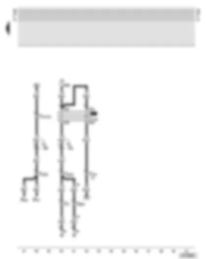
| D | Ignition/starter switch |
| F189 | Tiptronic switch |
| J217 | Automatic gearbox control unit |
| K142 | Selector lever position P/N warning lamp |
| N110 | Selector lever lock solenoid |
| S5 | Fuse in fuse box |
| S231 | Fuse 31 in fuse box |
| T2am | 2-pin connector, black, on selector lever console |
| T10am | 10-pin connector, on selector lever console |
| T17m | 17-pin connector, blue, connector point, A pillar, right |
| A2 | Positive (+) connection (15), in dash panel wiring harness |
| A20 | Connection (15a), in dash panel wiring harness |
| A38 | Positive (+) connection -2- (15a), in dash panel wiring harness |
| A121 | Connection (high bus), in dash panel wiring harness |
| A122 | Connection (low bus), in dash panel wiring harness |
| U5 | Connection -2- (15), in automatic gearbox wiring harness |
| • | CAN bus (data wire) |
| B | Starter |
| D | Ignition/starter switch |
| J207 | Starter inhibitor relay |
| M16 | Reversing light bulb, left |
| M17 | Reversing light bulb, right |
| T1h | Single connector, black, in engine compartment, right |
| T2dt | 2-pin connector, black, in engine compartment, right |
| T9 | 9-pin connector, brown, at starter inhibitor relay |
| T10f | 10-pin connector, brown, connector point, A pillar, left |
| T10m | 10-pin connector, blue, connector point, electronics box, plenum chamber |
| T10o | 10-pin connector, brown, connector point, electronics box, plenum chamber |
| T17m | 17-pin connector, blue, connector point, A pillar, right |
| A41 | Positive (+) connection (50), in dash panel wiring harness |
| A87 | Connection (RF (reversing light)), in dash panel wiring harness |
| * | Applies to S6 and RS6 models only |

 Deutsch
 English
 English
 Español
 Français
 Nederlands
 Русский


