ANTI-LOCK BRAKES
Anti-lock Brakes Wiring Diagram for Jaguar XJR 2004
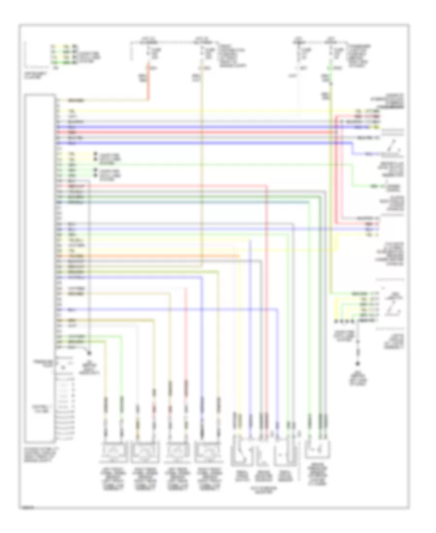
List of elements for Anti-lock Brakes Wiring Diagram for Jaguar XJR 2004:
- (inside of steering column steering angle sensor
- Active brake booster
- Al1
- Al4
- Brake booster solenoid
- Brake fluid level switch (in fluid reservoir)
- Brake pressure sensor (on brake master cylinder)
- Computer data lines system
- Control valves
- Cr49
- Dsc switch
- Dynamic stability control module (right front of engine compt)
- Ec4
- Ec7
- Front distribution fuse box (at right front of engine compt)
- Fuse f17 5a
- Fuse f20 30a
- Fuse f22 30a
- Fuse f33 5a
- G2 (behind right headlight)
- G32 (behind left side of dash)
- Hot at all times
- Hot in run
- Instrument cluster
- Ip6
- J-gate module (at j gate assembly)
- Left front wheel speed sensor (left front wheel hub assembly)
- Left rear wheel speed sensor (left rear wheel hub assembly)
- Nca
- Passenger junction fuse box (behind right end of dash)
- Pedal force switch
- Pedal travel sensor
- Pressure pump
- Red
- Right front wheel speed sensor (right front wheel hub assembly)
- Right rear wheel speed sensor (right rear wheel hub assembly)
- Sliding roof module (in roof console)
- Speed signal
- Yaw rate & lateral acceleration sensors (under center console)
 Čeština
 Dansk
Dansk Deutsch
 Ελληνικά
 English
 English
 Español
 Suomi
Suomi Français
 Français
 עברית
עברית Hrvatski
 Magyar
 Italiano
 한국어
한국어 Nederlands
 Polski
 Português
 Português
 Română
 Русский
 Slovenčina
 Slovenščina
 Svenska
 Türkçe
 中文 (中国)
 日本語
日本語