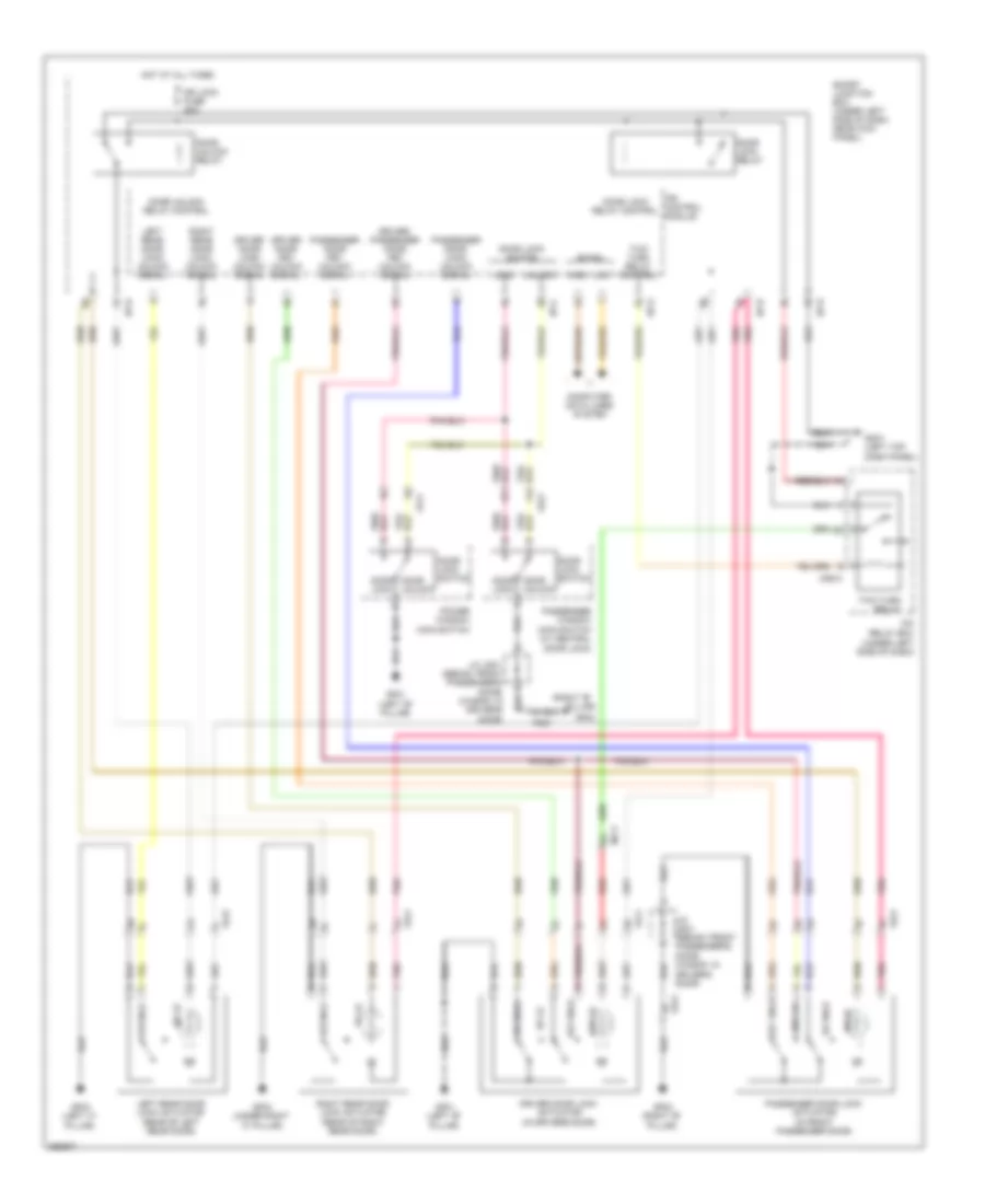
ANTI-THEFT
Forced Entry Wiring Diagram for Hyundai Elantra Limited 2012
 https://portal-diagnostov.com/license.html
Automotive Electricians Portal FZCO
Automotive Electricians Portal FZCO
https://portal-diagnostov.com/license.html
https://portal-diagnostov.com/license.html
Automotive Electricians Portal FZCO
Automotive Electricians Portal FZCO
List of elements for Forced Entry Wiring Diagram for Hyundai Elantra Limited 2012:
- (right "b"
- (under left side of dash)
- B-can
- Computer data lines system
- Door lock
- Door lock relay
- Door lock relay control
- Door lock switch
- Door unlock
- Door unlock relay
- Door unlock relay control
- Dr lk
- Dr lock fuse 20a
- Dr unlk
- Driver door key unlock signal
- Driver door lock actuator (in driver's door)
- Driver door lock/ unlock signal
- Driver/ passenger door key unlock signal
- Fd11
- Fd21
- Fd31
- Fd41
- Gf01 (left "b" pillar)
- Gf02
- Gf02 (right "b" pillar)
- Gf03 (left "c" pillar)
- Gf04 (under right "c" pillar)
- Gm01 (left top dash panel)
- High
- Hot at all times
- I/p-b
- I/p-c
- I/p-g
- I/p-h
- Icm relay box
- Ips control module
- J/c jd01 (sedan: front passenger's door) (wagon: in driver's door)
- Key lk
- Key unlk
- Left rear door lock actuator (rear of left rear door)
- Left rear door lock/ unlock signal
- Lock
- Low
- M06-a
- Mf11
- Passenger door key unlock signal
- Passenger door lock actuator (in front passenger door)
- Passenger door lock/ unlock signal
- Passenger window main switch (w/ central door lock)
- Pillar)
- Pnk
- Power window main switch
- Red
- Right rear door lock actuator (rear of right rear door)
- Right rear door lock/ unlock signal
- Smart junction box (under left side of dash, near kick panel)
- Two turn relay
- Two turn relay control
- Unlock
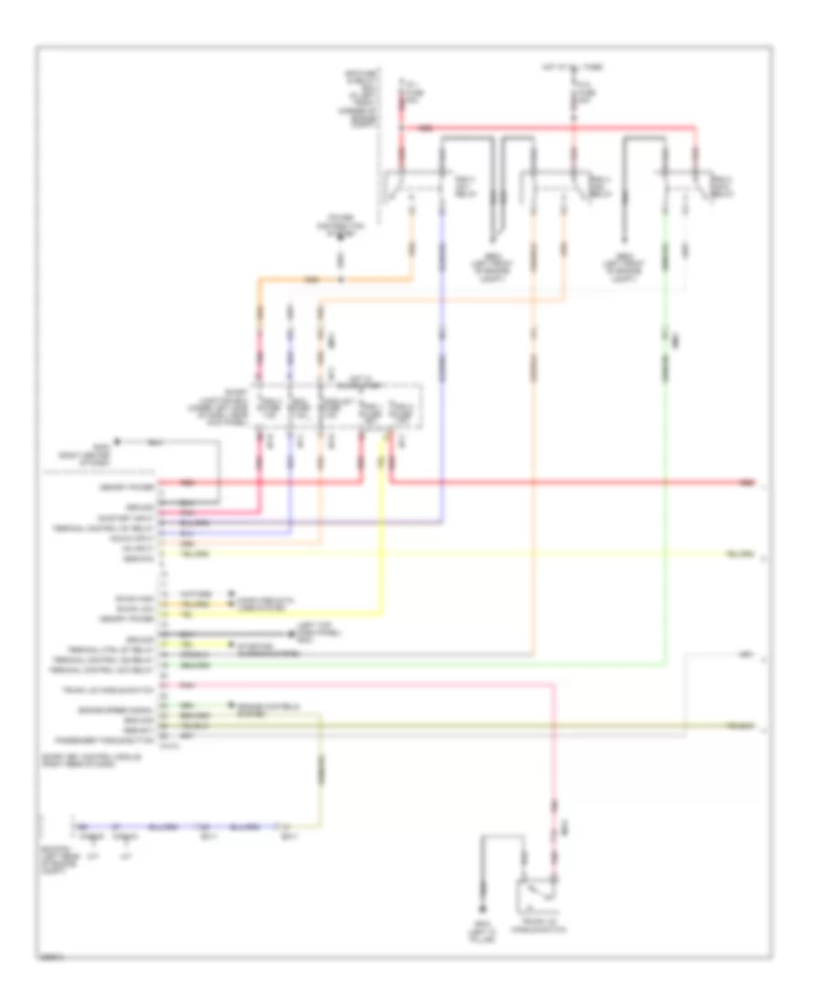
Immobilizer Wiring Diagram, with Smart Key System (1 of 3) for Hyundai Elantra Limited 2012
 https://portal-diagnostov.com/license.html
Automotive Electricians Portal FZCO
Automotive Electricians Portal FZCO
https://portal-diagnostov.com/license.html
https://portal-diagnostov.com/license.html
Automotive Electricians Portal FZCO
Automotive Electricians Portal FZCOList of elements for Immobilizer Wiring Diagram, with Smart Key System (1 of 3) for Hyundai Elantra Limited 2012:
- (left top dash panel) gm01
- A/t
- Acc/in input
- B-can high
- B-can low
- Bcm fuse 7.5a
- Cng-aa
- Cng-mk
- Computer data lines system
- E/r fuse & relay box (in left front corner of engine compt)
- Ec11
- Ecm/pcm (left rear of engine compt)
- Em11
- Em61
- Ems com
- Engine controls system
- Engine speed signal
- Ge02 (left front of engine compt)
- Gf03 (left "c" pillar)
- Gm02 (right center of dash)
- Ground
- Hot at all times
- Hot in on or start
- I/p-f
- I/p-h
- Ig 1 fuse 40a
- Ig 2 fuse 40a
- M/t
- M13-a
- Memory power
- Mf61
- Module 7 fuse 7.5a
- On input
- On/start input
- Passenger toggle button
- Pdm 1 fuse 25a
- Pdm 2 (acc) relay
- Pdm 2 fuse 7.5a
- Pdm 3 (ig1) relay
- Pdm 3 fuse 7.5a
- Pdm 4 (ig2) relay
- Pnk
- Power distribution system
- Red
- Smart junction box (under left side of dash, near kick panel)
- Smart key control module (right rear of dash)
- Ssb sw1
- Ssb sw2
- Starting/ charging system
- Terminal control acc relay
- Terminal control ig1 relay
- Terminal control ig2 relay
- Terminal ctrl st relay
- Trunk lid handle switch
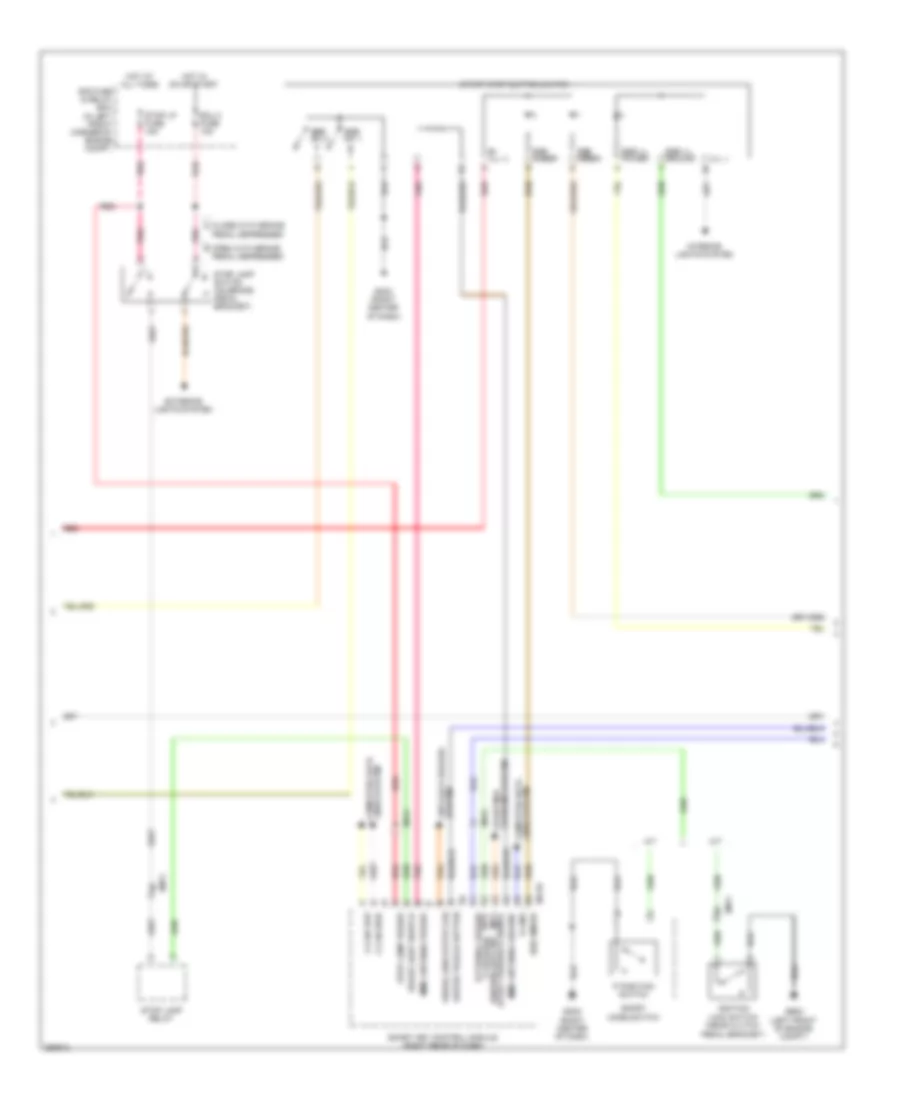
Immobilizer Wiring Diagram, with Smart Key System (2 of 3) for Hyundai Elantra Limited 2012
 https://portal-diagnostov.com/license.html
Automotive Electricians Portal FZCO
Automotive Electricians Portal FZCO
https://portal-diagnostov.com/license.html
https://portal-diagnostov.com/license.html
Automotive Electricians Portal FZCO
Automotive Electricians Portal FZCOList of elements for Immobilizer Wiring Diagram, with Smart Key System (2 of 3) for Hyundai Elantra Limited 2012:
- (ill -)
- A/t
- B+ (ill +)
- Brake light switch
- C-can high
- C-can low
- Charging system starting/
- Close with brake a
- Driver toggle button
- E/r fuse & relay box (in left front corner of engine compt)
- Ecu 3 fuse 10a
- Em11
- Exterior lights system
- External buzzer
- Ge02 (left front of engine compt)
- Gm02 (right center of dash)
- Hot at all times
- Hot in on or start
- Ignition lock switch (near clutch
- Immo antenna ground
- Immo antenna power
- Interior lights system
- K-line
- Lines system computer data
- M/t
- M13-b
- Mf61
- Open with brake b
- P position ignition lock sw
- P position switch
- Pedal bracket)
- Pedal depressed
- Pnk
- Red
- Smart key control module (right rear of dash)
- Sport mode switch
- Ssb amber
- Ssb green
- Ssb ill ground
- Ssb ill power
- Ssb sw 1
- Ssb sw 2
- Start feedback signal (m/t) (a/t)
- Start stop button switch
- Stop lamp power
- Stop lamp relay
- Stop lamp switch (on brake pedal bracket)
- Stop lp fuse 15a
- System anti-lock brakes
- Wheel sen output (fr)
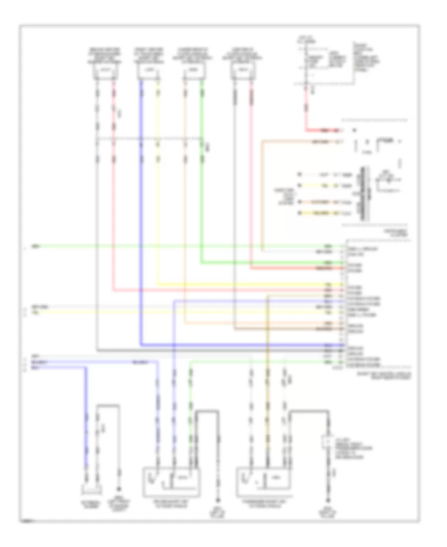
Immobilizer Wiring Diagram, with Smart Key System (3 of 3) for Hyundai Elantra Limited 2012
 https://portal-diagnostov.com/license.html
Automotive Electricians Portal FZCO
Automotive Electricians Portal FZCO
https://portal-diagnostov.com/license.html
https://portal-diagnostov.com/license.html
Automotive Electricians Portal FZCO
Automotive Electricians Portal FZCOList of elements for Immobilizer Wiring Diagram, with Smart Key System (3 of 3) for Hyundai Elantra Limited 2012:
- (behind center of rear bumper) smart key bumper antenna
- (center of floor console) smart key antenna (interior 1)
- (front center of trunk area) smart key trunk antenna
- (under rear of floor console) smart key antenna (interior 2)
- (wagon: in driver's door)
- Antenna power
- Computer data lines system
- Driver smart key outside handle
- Ee11
- External buzzer
- Fd11
- Fd21
- Fr11
- Ge02 (left front of engine compt)
- Gf01 (left "b" pillar)
- Gf02 (right "b" pillar)
- Ground
- High
- Hot at all times
- I/p-h
- Immo ind
- Instrument cluster
- J/c jd01 (sedan: front passenger's door)
- Key out ind
- Leak current autocut device
- Lock
- Low
- M13-c
- Memory fuse 10a
- Mf61
- Micom
- Nca
- Passenger smart key outside handle
- Power
- Red
- Smart junction box (under left side of dash, near kick panel)
- Smart key control module (right rear of dash)
- Ssb green
- Ssb ill ground
- Ssb ill power
- Transceiver b-can
- Transceiver c-can
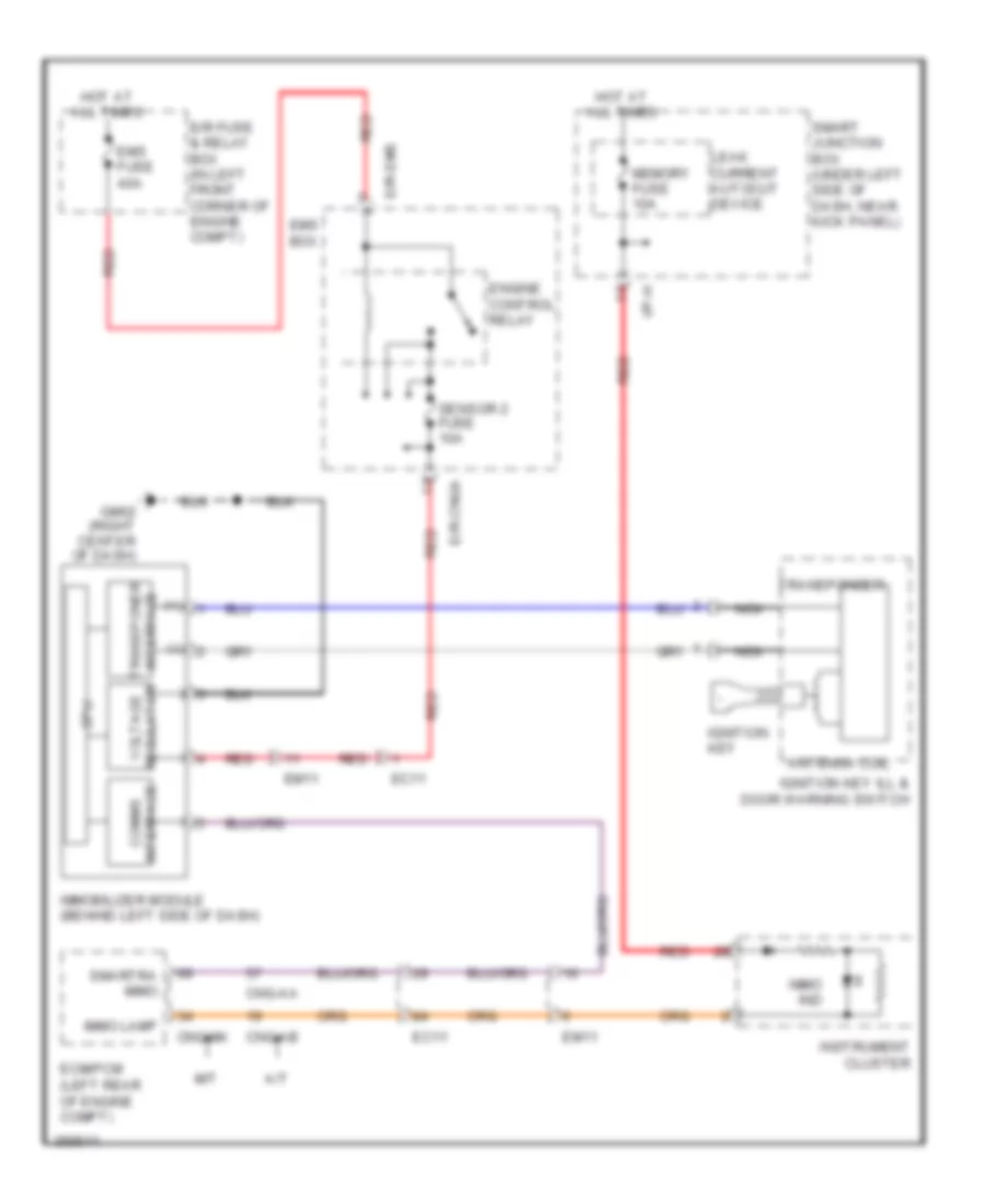
Immobilizer Wiring Diagram, without Smart Key System for Hyundai Elantra Limited 2012
 https://portal-diagnostov.com/license.html
Automotive Electricians Portal FZCO
Automotive Electricians Portal FZCO
https://portal-diagnostov.com/license.html
https://portal-diagnostov.com/license.html
Automotive Electricians Portal FZCO
Automotive Electricians Portal FZCOList of elements for Immobilizer Wiring Diagram, without Smart Key System for Hyundai Elantra Limited 2012:
- (+)
- (-)
- A/t
- Antenna coil
- Cng-aa
- Cng-ab
- Cng-mk
- Cpu
- E/r fuse & relay box (in left front corner of engine compt)
- E/r-cnga
- E/r-ems
- Ec11
- Ecm/pcm (left rear of engine compt)
- Em11
- Ems box
- Ems fuse 40a
- Engine control relay
- Gm02 (right center of dash)
- Hot at all times
- I/p-h
- Ignition key
- Ignition key ill & door warning switch
- Immo ind
- Immo lamp
- Immobilizer module (behind left side of dash)
- Instrument cluster
- Interface comms
- Interface transponer
- Leak current autocut device
- M/t
- Memory fuse 10a
- Nca
- Red
- Regulator voltage
- Sensor 2 fuse 10a
- Smart junction box (under left side of dash, near kick panel)
- Smartra immo
- Transponder

 Čeština
 Dansk
Dansk Deutsch
 Ελληνικά
 English
 English
 Español
 Suomi
Suomi Français
 Français
 עברית
עברית Hrvatski
 Magyar
 Italiano
 한국어
한국어 Nederlands
 Polski
 Português
 Português
 Română
 Русский
 Slovenčina
 Slovenščina
 Svenska
 Türkçe
 中文 (中国)
