CRUISE CONTROL
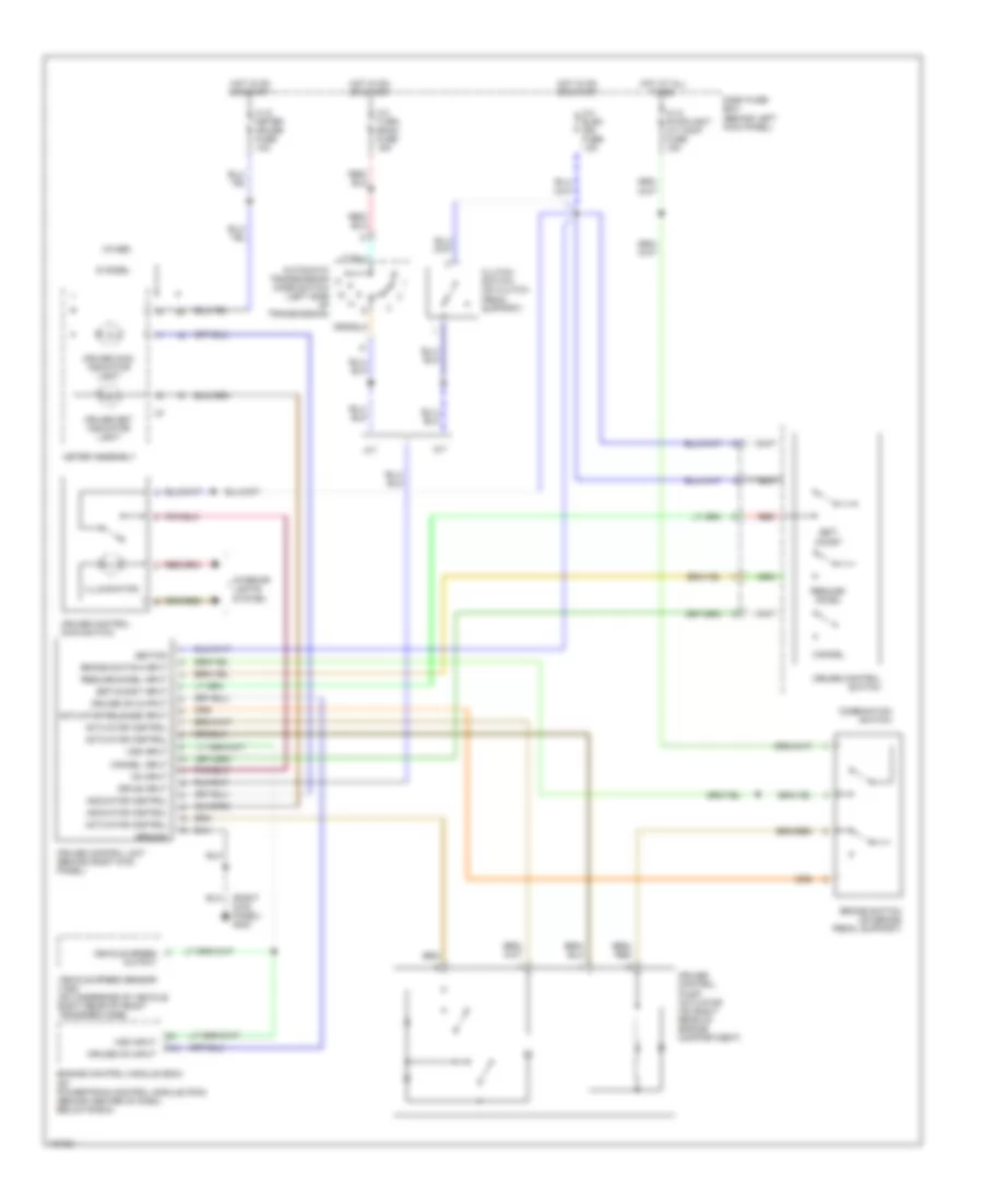
Cruise Control Wiring Diagram for Isuzu Trooper LS 1998
 https://portal-diagnostov.com/license.html
Automotive Electricians Portal FZCO
Automotive Electricians Portal FZCO
https://portal-diagnostov.com/license.html
https://portal-diagnostov.com/license.html
Automotive Electricians Portal FZCO
Automotive Electricians Portal FZCO
List of elements for Cruise Control Wiring Diagram for Isuzu Trooper LS 1998:
- (right kick panel) g203
- A/t
- Actuator control
- Actuator release input
- Automatic transmission mode switch (left side of transmission)
- Brake switch (on brake pedal support)
- Brake switch input
- C-10 meter gauge fuse 10a
- C-14 stoplight a/t cont fuse 15a
- C-3 turn back fuse 15a
- C-4 elec ign fuse 15a
- Cancel
- Cancel input
- Clutch switch (on clutch pedal support)
- Combination switch
- Cruise control main switch
- Cruise control pump/ actuator (on right rear of engine compartment)
- Cruise control switch
- Cruise control unit (behind right kick panel)
- Cruise main indicator light
- Cruise on input
- Cruise on output
- Cruise set indicator light
- Dash fuse box (behind left kick panel)
- Drive input
- Engine control module (ecm) or powertrain control module (pcm) (behind center of dash, below radio)
- F10
- Ground
- Hot at all times
- Hot in on or start
- I-9
- Ignition
- Illumination
- Indicator control
- Interior lights system
- M/t
- Meter assembly
- On input
- Other
- Red
- Resume/ accel
- Resume/accel input
- S model
- Set/ coast
- Set/coast input
- Vehicle speed output
- Vehicle speed sensor (vss) (on underside of vehicle, right rear of front transfer case)
- Vss input
 Čeština
 Dansk
Dansk Deutsch
 Ελληνικά
 English
 English
 Español
 Suomi
Suomi Français
 Français
 עברית
עברית Hrvatski
 Magyar
 Italiano
 한국어
한국어 Nederlands
 Polski
 Português
 Português
 Română
 Русский
 Slovenčina
 Slovenščina
 Svenska
 Türkçe
 中文 (中国)
 日本語
日本語
