
 Čeština
 Dansk
Dansk Deutsch
 Ελληνικά
 English
 English
 Español
 Suomi
Suomi Français
 Français
 עברית
עברית Hrvatski
 Magyar
 Italiano
 한국어
한국어 Nederlands
 Polski
 Português
 Português
 Română
 Русский
 Slovenčina
 Slovenščina
 Svenska
 Türkçe
 中文 (中国)

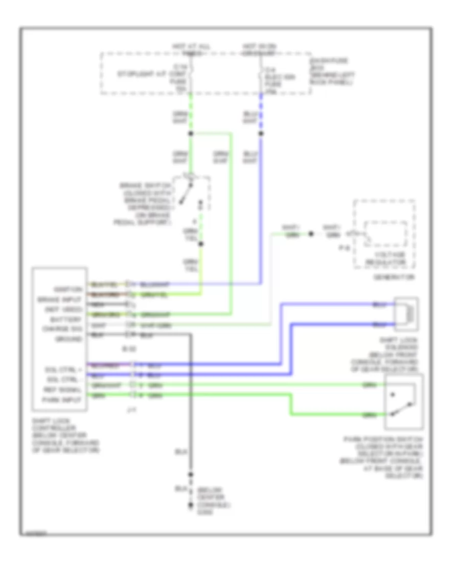
SHIFT INTERLOCKS
Shift Interlock Wiring Diagram for Isuzu Trooper LS 1998
List of elements for Shift Interlock Wiring Diagram for Isuzu Trooper LS 1998:

ANTI-LOCK BRAKESAIR CONDITIONINGCOMPUTER DATA LINESCRUISE CONTROLANTI-THEFTENGINE PERFORMANCEGROUND DISTRIBUTIONHORNINTERIOR LIGHTSHEADLIGHTSINSTRUMENT CLUSTEREXTERIOR LIGHTSDEFOGGERSPOWER DISTRIBUTIONPOWER DOOR LOCKSPOWER SEATSRADIOPOWER WINDOWSPOWER TOP/SUNROOFSTARTING/CHARGINGPOWER MIRRORSSUPPLEMENTAL RESTRAINTSTRANSMISSIONSHIFT INTERLOCKSWARNING SYSTEMSWIPER/WASHER