WARNING SYSTEMS
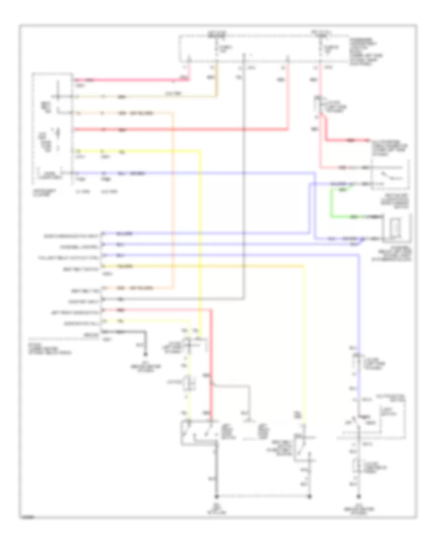
Warning Systems Wiring Diagram for Hyundai Elantra GT 2005
 https://portal-diagnostov.com/license.html
Automotive Electricians Portal FZCO
Automotive Electricians Portal FZCO
https://portal-diagnostov.com/license.html
https://portal-diagnostov.com/license.html
Automotive Electricians Portal FZCO
Automotive Electricians Portal FZCO
List of elements for Warning Systems Wiring Diagram for Hyundai Elantra GT 2005:
- Chime bell (below left side of dash, right of steering column)
- Chime bell control
- Door ajar ind
- Door switch (all)
- Door warning switch input
- Etacm (under center of dash, below radio)
- Fuse 2 10a
- Fuse 25 15a
- G01 (left "b" pillar)
- G11 (behind center of dash)
- G12 (behind center of dash)
- Ground
- Head
- Hot at all times
- Hot in on or start
- I/p-g
- I/p-h
- Ignition key illumination & door warning switch
- Instrument cluster
- J/c m122
- J/c m27 (center of dash)
- J/c m33 (left side of dash)
- J/c m36 (left side of dash)
- Left front door lamp
- Left front door switch
- Light switch
- M01-2
- M09-1
- M09-2
- M10-1
- M10-2
- M25-1
- M25-2
- Micro computer
- Multifunction switch
- Multipurpose check connector (lower left side of dash)
- Nca
- Off
- On/start input
- Park
- Passenger compartment junction block (under left side of dash, near kick panel)
- Pnk
- Red
- Seat belt ind
- Seat belt switch
- Seat belt switch (in seat belt buckle)
- Taillight relay auto cut ctrl
- W/ trip
- W/o trip
 Čeština
 Dansk
Dansk Deutsch
 Ελληνικά
 English
 English
 Español
 Suomi
Suomi Français
 Français
 עברית
עברית Hrvatski
 Magyar
 Italiano
 한국어
한국어 Nederlands
 Polski
 Português
 Português
 Română
 Русский
 Slovenčina
 Slovenščina
 Svenska
 Türkçe
 中文 (中国)
 日本語
日本語
