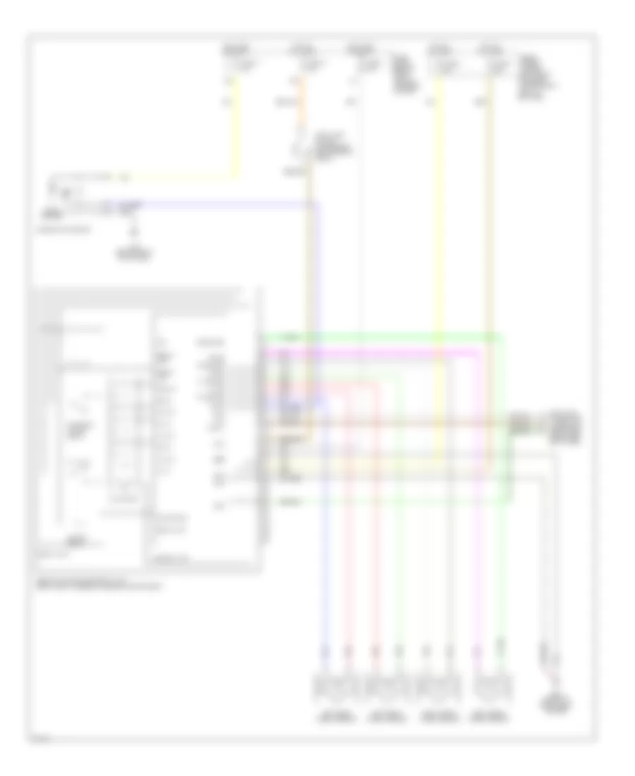
СИСТЕМА АНТИБЛОКИРОВОЧНОЙ ТОРМОЗНОЙ СИСТЕМЫ ABS
Электросхема антиблокировочной тормозной системы АБС (ABS) для Infiniti G20 2002
 https://portal-diagnostov.com/license.html
Automotive Electricians Portal FZCO
Automotive Electricians Portal FZCO
https://portal-diagnostov.com/license.html
https://portal-diagnostov.com/license.html
Automotive Electricians Portal FZCO
Automotive Electricians Portal FZCO
Электросхема антиблокировочной тормозной системы АБС (ABS) для Infiniti G20 2002 - Список элементов:
- 15d
- Abs actuator & electrical unit (right front corner of engine compartment)
- Abs ind
- Actuator
- Bls
- Combination meter
- Control unit
- Data link connector (under left dash panel, near fuse box cover)
- Diag l
- E56 (front of right front fender)
- Fl in
- Fl out
- Fl ss
- Fl ss gnd
- Fr in
- Fr ss
- Fr ss gnd
- Fuse & fusible link box (left front of engine compartment, next to battery)
- Fuse 11 10a
- Fuse 14 15a
- Fuse 3 7.5a
- Fuse block (behind dash, left of steering column)
- Fuse f 40a
- Fuse h 40a
- Gnd
- Gnd gnd
- Hot at all times
- Hot in on or start
- Ign
- Left front wheel sensor
- Left rear wheel sensor
- M76 (behind right kick panel)
- Motor mon
- Motor relay
- Pnk
- Red
- Relay act
- Relay mon
- Relay unit
- Right front wheel sensor
- Right rear wheel sensor
- Rl in
- Rl out
- Rl ss
- Rl ss gnd
- Rr in
- Rr out
- Rr ss
- Rr ss gnd
- Rxd
- Sila
- Solenoid valve relay
- Solid state
- Stop lamp switch (on bracket, above brake pedal)
- Txd
 Čeština
 Dansk
Dansk Deutsch
 Ελληνικά
 English
 English
 Español
 Suomi
Suomi Français
 Français
 עברית
עברית Hrvatski
 Magyar
 Italiano
 한국어
한국어 Nederlands
 Polski
 Português
 Português
 Română
 Русский
 Slovenčina
 Slovenščina
 Svenska
 Türkçe
 中文 (中国)
 日本語
日本語
