ENGINE PERFORMANCE
3.6L VIN 7
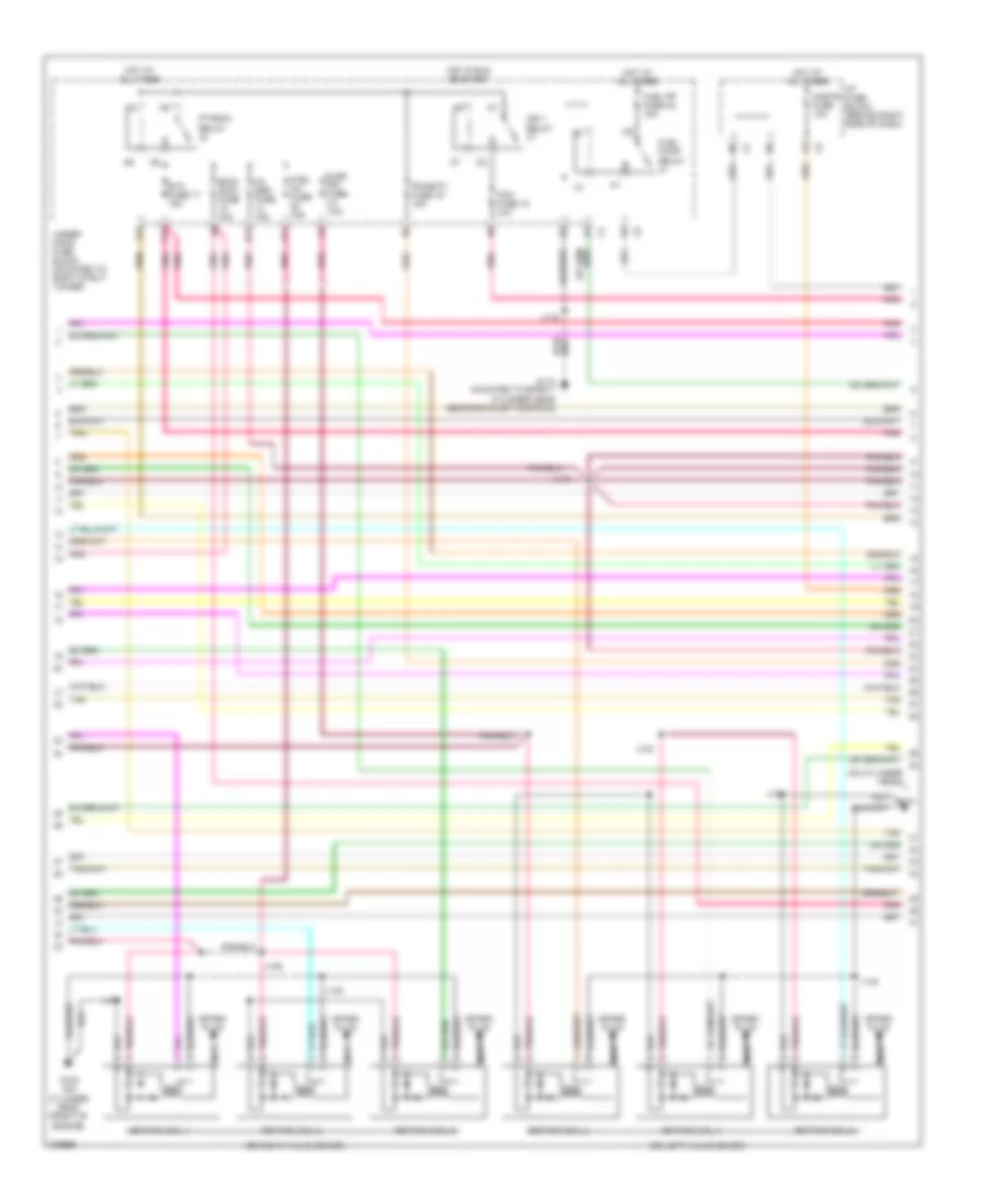
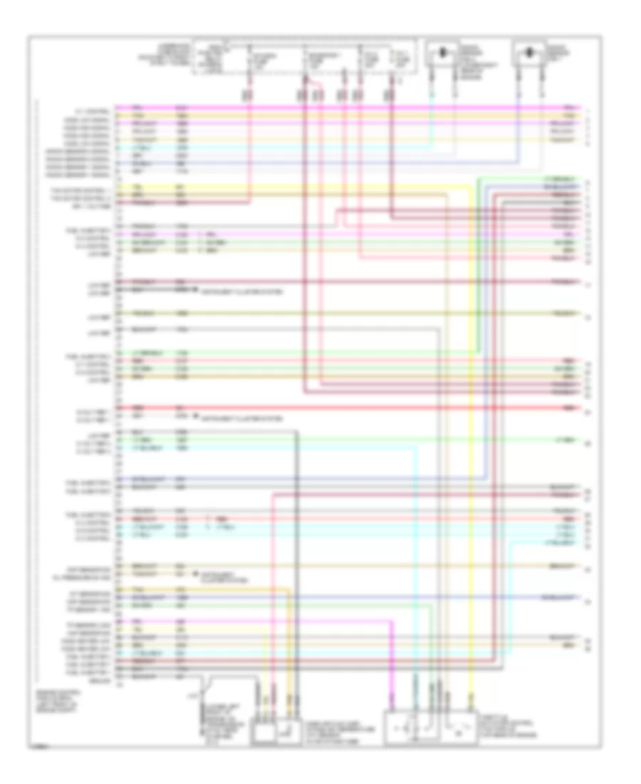
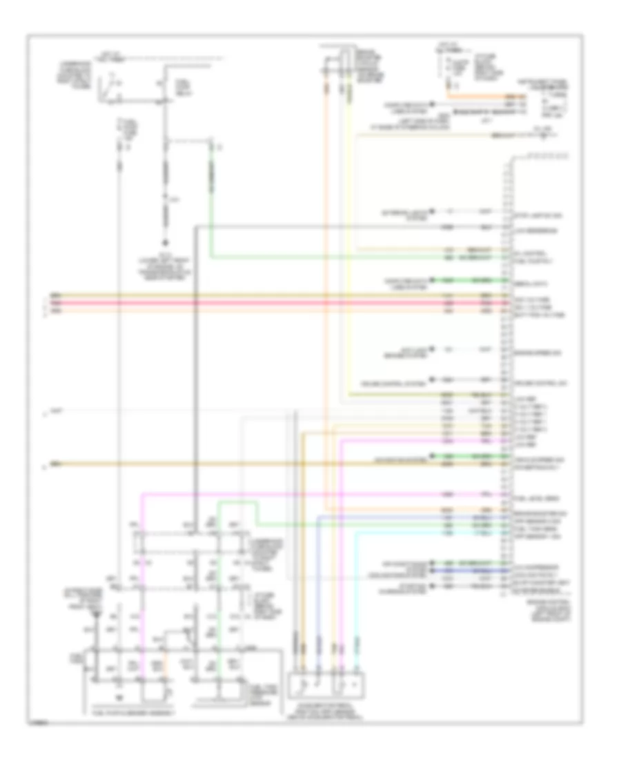
3.6L VIN 7, Engine Performance Wiring Diagram (1 of 4) for Buick Allure CXS 2008
 https://portal-diagnostov.com/license.html
Automotive Electricians Portal FZCO
Automotive Electricians Portal FZCO
https://portal-diagnostov.com/license.html
https://portal-diagnostov.com/license.html
Automotive Electricians Portal FZCO
Automotive Electricians Portal FZCO
List of elements for 3.6L VIN 7, Engine Performance Wiring Diagram (1 of 4) for Buick Allure CXS 2008:
- (1: right top of engine) (2: left top of engine) (3: right top center of engine) (4: left top center of engine) (5: right top rear of engine) (6: left top rear of engine)
- +5v
- +5v ref
- +5v ref 2
- Bare
- Ckp sens sig
- Cmp sig
- Cmp sol ctrl
- Crankshaft (ckp) position sensor (right rear of engine block)
- Ect sig
- Engine control module (top of engine)
- Engine oil pressure (eop) switch
- Evap sol ctrl
- Fuel injectors
- G103 (redundant ground from ecm to even bank cylinder head)
- G115 (mounted to bank 1 cylinder head above exhaust manifold)
- Gen fdc sig
- Gen to sig
- Gnd
- Ground
- Heated oxygen sensor 1 (at rear of cylinder head, in exhaust manifold)
- Heated oxygen sensor 2 (in exhaust system, rear of catalytic converter)
- Ho2s hi sig
- Ho2s lo ctrl
- Ho2s pmp ct
- Ign 1 ctrl
- Ign 2 ctrl
- Ign 3 ctrl
- Ign 4 sig
- Ign 5 ctrl
- Ign 6 ctrl
- Inj 1 ctrl
- Inj 2 ctrl
- Inj 3 ctrl
- Inj 4 ctrl
- Inj 5 ctrl
- Inj 6 ctrl
- J104
- J108
- Knock sensor (ks) 1 (right side of engine)
- Knock sensor (ks) 2 (left side of engine block, below exhaust manifold)
- Ks 1 sig
- Ks 2 sig
- Low ref
- Map sig
- Nca
- Oil pres sig
- Pnk
- Pnk e
- Starting/ charging system
- Tac mtr ctrl-1
- Tac mtr ctrl-2
- Tan
- Tp sig
- Tp2 sig
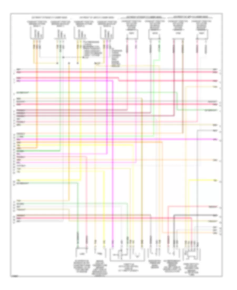
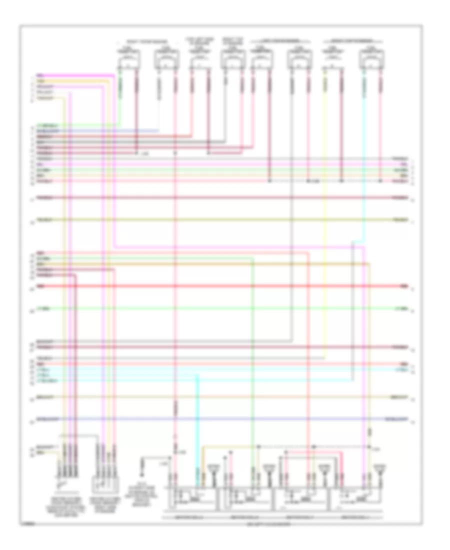
3.6L VIN 7, Engine Performance Wiring Diagram (2 of 4) for Buick Allure CXS 2008
 https://portal-diagnostov.com/license.html
Automotive Electricians Portal FZCO
Automotive Electricians Portal FZCO
https://portal-diagnostov.com/license.html
https://portal-diagnostov.com/license.html
Automotive Electricians Portal FZCO
Automotive Electricians Portal FZCOList of elements for 3.6L VIN 7, Engine Performance Wiring Diagram (2 of 4) for Buick Allure CXS 2008:
- (on cylinder head)
- (on left valve cover)
- (on right valve cover)
- A11
- C11
- Cnstr fuse 10a
- D11
- Elek ign fuse 15a
- Emis- sion fuse 10a
- Etc fuse 17 15a
- F12
- Fuel inj fuse 15a
- Fuel pp fuse 22 15a
- Fuel pump relay
- G115 (mounted to bank 1 cylinder head above exhaust manifold)
- G130 (on cylinder head, front of engine)
- G131
- Hot at all times
- Hot in run or start
- I/p fuse block (behind right side of dash)
- Ign 1 relay
- Ignition coil 1
- Ignition coil 2
- Ignition coil 3
- Ignition coil 4
- Ignition coil 5
- Ignition coil 6
- J103
- J106
- J110
- J116
- J130
- J131
- J132
- J133
- Nca
- O2 ssr fuse 15a
- P/train relay
- Pcm fuse 15 10a
- Pcm/etc fuse 16 15a
- Pnk
- Spark plug
- Tan
- Under- hood fuse block (mounted to right strut tower)
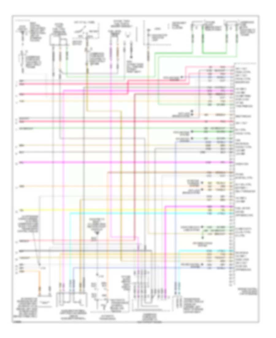
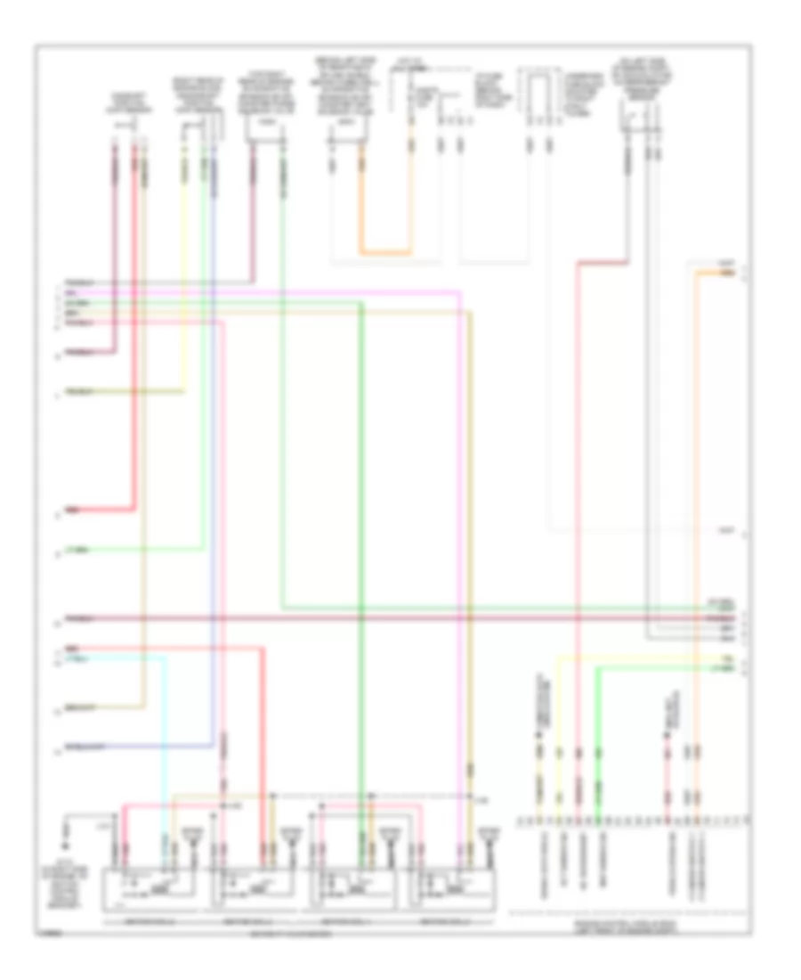
3.6L VIN 7, Engine Performance Wiring Diagram (3 of 4) for Buick Allure CXS 2008
 https://portal-diagnostov.com/license.html
Automotive Electricians Portal FZCO
Automotive Electricians Portal FZCO
https://portal-diagnostov.com/license.html
https://portal-diagnostov.com/license.html
Automotive Electricians Portal FZCO
Automotive Electricians Portal FZCOList of elements for 3.6L VIN 7, Engine Performance Wiring Diagram (3 of 4) for Buick Allure CXS 2008:
- (in on-engine wiring harness, 34.5 cm from engine control module)
- (on front of left cylinder head)
- (on front of right cylinder head)
- +5v
- A/c refrigerant pressure sensor (on left side of engine compt, on accumulator)
- Bank 2)
- Barometric pressure (baro) sensor
- Camshaft position actuator solenoid (exhaust bank 1)
- Camshaft position actuator solenoid (exhaust bank 2)
- Camshaft position actuator solenoid (intake bank 1)
- Camshaft position actuator solenoid (intake bank 2)
- Camshaft position sensor (exhaust bank 1)
- Camshaft position sensor (exhaust bank 2)
- Camshaft position sensor (intake
- Camshaft position sensor (intake bank 1)
- Engine coolant temperature sensor (left side of engine block, above exhaust manifold)
- Evaporative emission (evap) canister purge solenoid valve (top center of engine)
- J119
- Low ref
- Mass air flow/ intake air temperature sensor (in air intake tube)
- Pnk
- Signal
- Tan
- Throttle actuator control module (at throttle body)
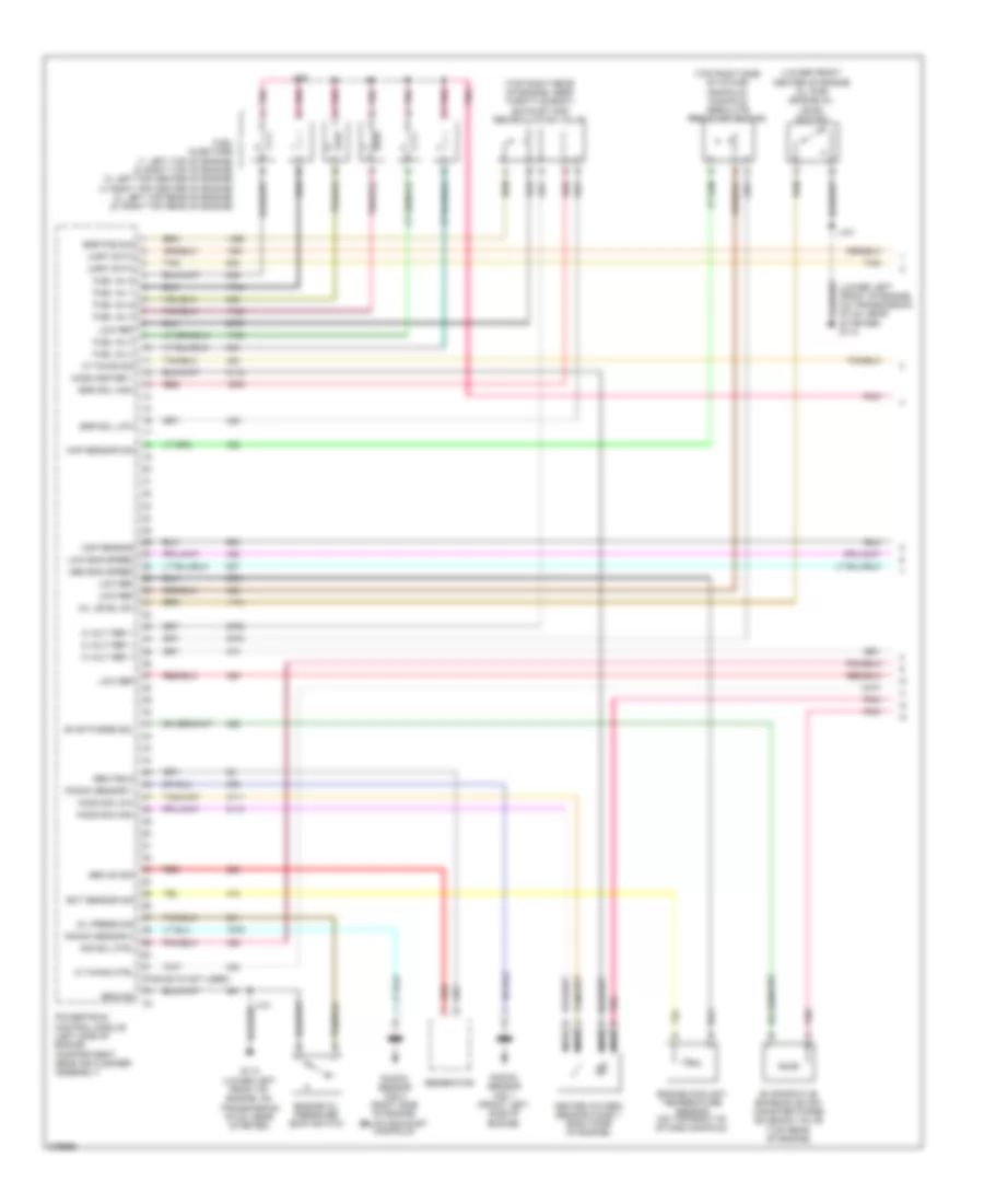
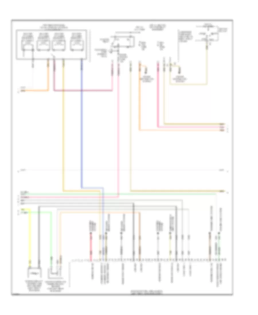
3.6L VIN 7, Engine Performance Wiring Diagram (4 of 4) for Buick Allure CXS 2008
 https://portal-diagnostov.com/license.html
Automotive Electricians Portal FZCO
Automotive Electricians Portal FZCO
https://portal-diagnostov.com/license.html
https://portal-diagnostov.com/license.html
Automotive Electricians Portal FZCO
Automotive Electricians Portal FZCOList of elements for 3.6L VIN 7, Engine Performance Wiring Diagram (4 of 4) for Buick Allure CXS 2008:
- (ims)
- (in fuel tank) fuel pump & sender assembly
- (in fuel tank) fuel tank pressure (ftp) sensor
- (in off-engine wiring harness, 32 cm from underhood fuse block towards transmission control module)
- (mounted to bank 1 cylinder head above exhaust manifold) g115
- +5v ref 1
- +5v ref 2
- A/c ref pres
- A12
- Acc
- Accelerator pedal (app) position sensor (above accelerator pedal)
- Air conditioning system
- Anti-lock brake system
- App sens 2 sig
- App sens sig
- Automatic transmission
- Automatic transmission internal
- B12
- Battery +
- Body control module (bcm) (below left side of dash, left of steering column)
- C12
- Cc sw sig
- Class 2 data
- Clu rly ctrl
- Computer data lines system
- Cooling fans system
- Cruise control system
- D10
- D12
- Delv torque sig
- E11
- Eng spd sig
- Engine control module (ecm) (top of engine)
- Evap sol ctrl
- Evaporative emissions (evap) canister vent solenoid valve (behind left side of rear fascia splash shield, behind wheelwell)
- Fan rly ctrl
- Fuel lev sig
- Fuel level sensor
- G302 (in right door sill, forward of right front seat)
- Gmlan bus+
- Gmlan bus-
- Ho2s hi sig
- Ho2s lo ctrl
- Ho2s lo sig
- Hot at all times
- I/p fuse block (behind right side of dash)
- I/p fuse block (behind right x1 side of dash)
- Iat sig
- Ign
- Ign 1 volt
- Ign 3 volt
- Ignition switch
- Instrument panel cluster
- J116
- J118
- Lan bus +
- Lan bus -
- Lock
- Logic
- Low ref
- Maf sig
- Main rly ctrl
- Malfunction indicator lamp
- Mil ctrl
- Mode switch
- Navigation system
- P/n
- P/n sig
- Pnk
- Req torq sig
- Rly coil ctrl
- Rly ctrl
- Run
- Start
- Starting/ charging system
- Stop lamp sw sig
- Stop lp sw
- Tan
- Tank pres sig
- Transmission control module (inside air cleaner, left front of engine compartment)
- Underhood fuse block (mounted to right strut tower)
- Underhood fuse block (mounted to right strut tower) x1
- Underhood fuse block (mounted to right strut x1 tower)
- Underhood fuse block x1 (mounted to right strut tower)
- Vss
3.8L VIN 2
3.8L VIN 2, Engine Performance Wiring Diagram (1 of 5) for Buick Allure CXS 2008
 https://portal-diagnostov.com/license.html
Automotive Electricians Portal FZCO
Automotive Electricians Portal FZCO
https://portal-diagnostov.com/license.html
https://portal-diagnostov.com/license.html
Automotive Electricians Portal FZCO
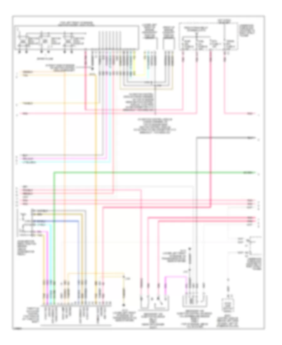
Automotive Electricians Portal FZCOList of elements for 3.8L VIN 2, Engine Performance Wiring Diagram (1 of 5) for Buick Allure CXS 2008:
- (lower front center of engine oil pan) engine oil level switch
- (lower left front of engine, on transmission stud, near starter) g113
- (pins 62-72 not used)
- (top right rear of engine, near throttle body) exhaust gas recirculation valve
- (top right side of intake manifold) manifold absolute pressure sensor
- 5 volt ref 1
- Air sol ctrl
- Cmp sensor
- Ect sensor sig
- Egr pos sig
- Egr sol high
- Egr sol low
- Engine coolant temperature sensor (on top right of intake manifold)
- Engine oil pressure (eop) switch
- Evap purge sol
- Evaporative emission (evap) canister purge solenoid valve (top rear of engine)
- Fuel inj 1
- Fuel inj 2
- Fuel inj 3
- Fuel inj 4
- Fuel inj 5
- Fuel inj 6
- Fuel injectors (1: left top of engine) (2: right top of engine) (3: left top center of engine) (4: right top center of engine) (5: left top rear of engine) (6: right top rear of engine)
- G113 (lower left front of engine, on transmission stud, near starter)
- Gen field
- Gen on sig
- Generator
- Ground
- Heated oxygen sensor (ho2s) 1 (right side of engine)
- Ho2s heater 1
- Ho2s sig high
- Ho2s sig low
- Ic timing ctrl
- Ic timing sig
- J101
- J109
- Knock sensor (ks) 1 (front left side of engine)
- Knock sensor (ks) 2 (right side of engine, below exhaust manifold)
- Knock sensor 1
- Knock sensor 2
- Low eng speed
- Low ref
- Map sensor sig
- Med eng speed
- Nca
- Oil level sw
- Oil press sig
- Pnk
- Powertrain control module (left side of engine compartment, near air cleaner assembly)
- Red
- Tan
- Uart data
3.8L VIN 2, Engine Performance Wiring Diagram (2 of 5) for Buick Allure CXS 2008
 https://portal-diagnostov.com/license.html
Automotive Electricians Portal FZCO
Automotive Electricians Portal FZCO
https://portal-diagnostov.com/license.html
https://portal-diagnostov.com/license.html
Automotive Electricians Portal FZCO
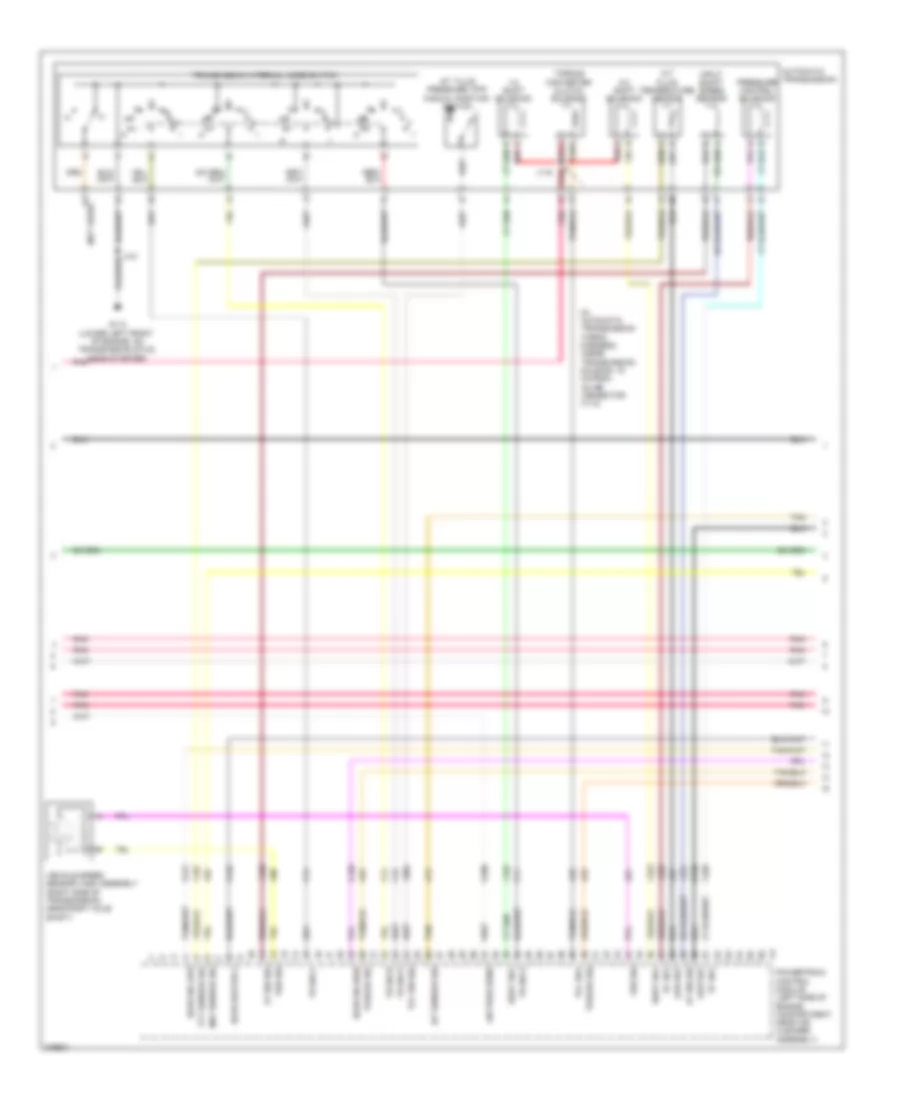
Automotive Electricians Portal FZCOList of elements for 3.8L VIN 2, Engine Performance Wiring Diagram (2 of 5) for Buick Allure CXS 2008:
- (front of engine) camshaft position sensor
- (in ignition control module wiring harness, on top of engine near ignition control module, 12 cm from inline connector x110 breakout, towards icm)
- (in ignition control module wiring harness, on top of engine near ignition control module, 5.5 cm from inline connector x110 breakout, towards icm)
- (in right side of engine, on ignition control module bracket)
- (lower left front of engine) crankshaft position sensor
- (top left front of engine) ignition control module (icm)
- 5 volt ref
- A11
- Aap sensor 1
- Accelerator pedal position sensor (above accelerator pedal)
- App sensor 2
- Body control module (behind left side of dash, left of steering column)
- C11
- Elek ign fuse 24 15a
- Etc fuse 17 15a
- From p/train relay (diagram 4 of 5)
- Fuel inj fuse 20 15a
- G112
- G113 (lower left front of engine, on transmission stud, near starter)
- Ground
- Hot in run or start
- Ign 1 volt
- Ignition coil/ module
- J101
- J102
- J144
- J145
- Low ref
- Pnk
- Primary uart
- Sec uart
- Secondary air injection control solenoid valve/pressure sensor bank 2 (pzev) (top of engine, above valve cover)
- Secondary air injection solenoid relay (pzev) (near air cleaner duct)
- Spark plugs
- Stop lamp
- Stop lamp switch signal
- Tan
- Throttle actuator control (tac) module (at throttle body)
- Trans sol fuse 21 10a
- Underhood fuse block (mounted to right strut tower)
- Vehicle spd
3.8L VIN 2, Engine Performance Wiring Diagram (3 of 5) for Buick Allure CXS 2008
 https://portal-diagnostov.com/license.html
Automotive Electricians Portal FZCO
Automotive Electricians Portal FZCO
https://portal-diagnostov.com/license.html
https://portal-diagnostov.com/license.html
Automotive Electricians Portal FZCO
Automotive Electricians Portal FZCOList of elements for 3.8L VIN 2, Engine Performance Wiring Diagram (3 of 5) for Buick Allure CXS 2008:
- (in automatic transmission wiring harness, inside transmission housing, 19 cm from inline connector x113)
- 1-2 shift solenoid
- 2-3 shift solenoid
- A red
- A/t fluid pressure (tfp) manual position switch
- A/t fluid temperature sensor
- Air pres sens
- At iss sig
- Automatic transmission
- B tan
- G113 (lower left front of engine, on transmission stud, near starter)
- Ho2s heater 2
- Ho2s sig high
- Ho2s sig low
- Iat sensor sig
- Input shaft speed sensor
- Low ref
- Maf sensor sig
- Pc sol
- Pnk
- Powertrain control module (left side of engine compartment, near air cleaner assembly)
- Pressure control solenoid
- Red j115
- Shift sol
- Tan
- Tcc sol
- Tcc sw sig
- Tft sensor sig
- Torque converter clutch solenoid
- Torque sig
- Tr sw a
- Tr sw b
- Tr sw c
- Tr sw p
- Transmission internal mode switch
- Vehicle speed sensor (vss) assembly (right side of transmission, near right axle shaft)
- Vss sig
- W (not used)
3.8L VIN 2, Engine Performance Wiring Diagram (4 of 5) for Buick Allure CXS 2008
 https://portal-diagnostov.com/license.html
Automotive Electricians Portal FZCO
Automotive Electricians Portal FZCO
https://portal-diagnostov.com/license.html
https://portal-diagnostov.com/license.html
Automotive Electricians Portal FZCO
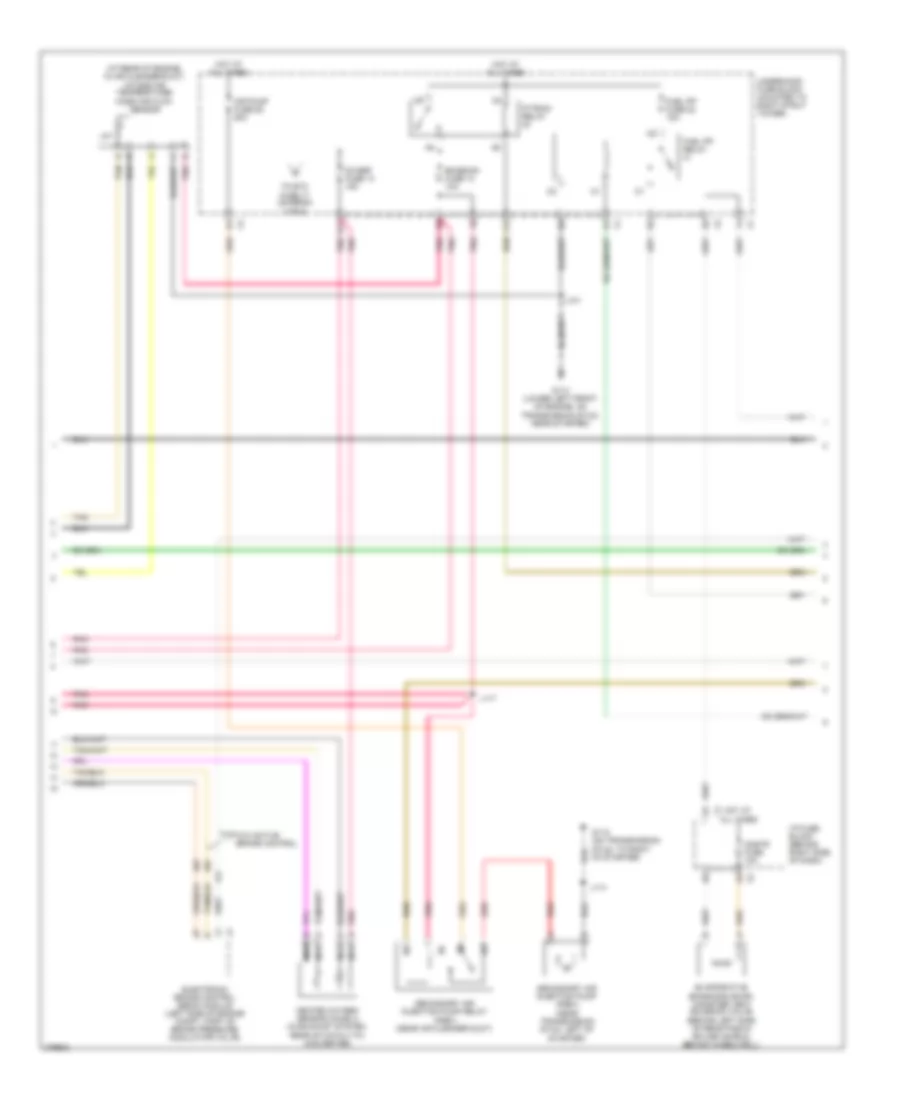
Automotive Electricians Portal FZCOList of elements for 3.8L VIN 2, Engine Performance Wiring Diagram (4 of 5) for Buick Allure CXS 2008:
- (at rear of engine, in air cleaner duct) intake air temperature/ mass air flow sensor
- Air pump fuse 25 50a
- Cnstr fuse 10a
- D11
- Electronic brake control (ebcm) module (left side of engine compt, part of brake pressure modulator valve)
- Emission fuse 12 10a
- Evaporative emissions (evap) canister vent solenoid valve (behind left side of rear fascia splash shield, behind wheelwell)
- F12
- Fuel pp fuse 22 15a
- Fuel pp relay
- G113 (lower left front of engine, on transmission stud, near starter)
- G115 (on transmission stud, to right of starter)
- Heated oxygen sensor (ho2s) 2 (in exhaust system, rear of catalytic converter)
- Hot at all times
- I/p fuse block (behind right side of dash)
- Iat
- J101
- J114
- J117
- Nca
- O2 ssr fuse 14 15a
- P/train relay
- Pnk
- Red
- Secondary air injection pump (pzev) (near transmission stud, left of starter)
- Secondary air injection pump relay (pzev) (near air cleaner duct)
- Tan
- To etc fuse 17 (diagram 2 of 5)
- Underhood fuse block (mounted to right strut tower)
- W/o active brake control
3.8L VIN 2, Engine Performance Wiring Diagram (5 of 5) for Buick Allure CXS 2008
 https://portal-diagnostov.com/license.html
Automotive Electricians Portal FZCO
Automotive Electricians Portal FZCO
https://portal-diagnostov.com/license.html
https://portal-diagnostov.com/license.html
Automotive Electricians Portal FZCO
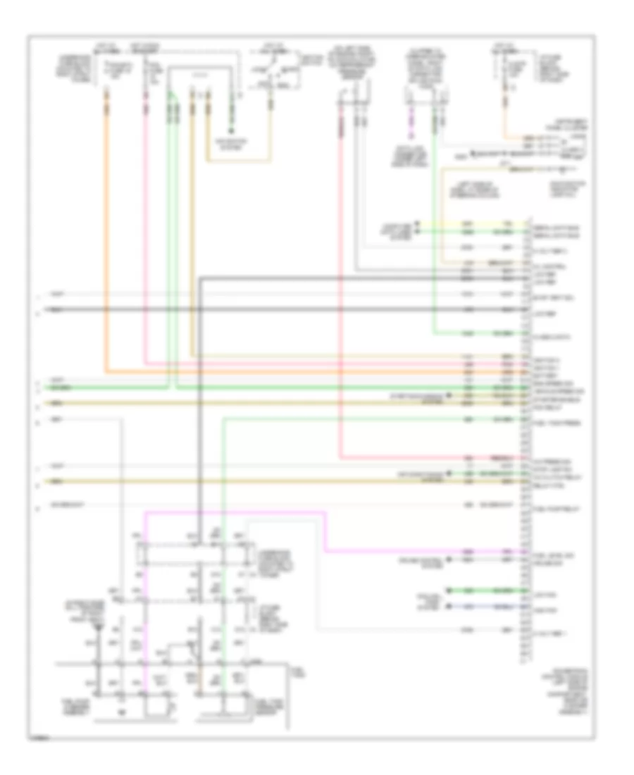
Automotive Electricians Portal FZCOList of elements for 3.8L VIN 2, Engine Performance Wiring Diagram (5 of 5) for Buick Allure CXS 2008:
- (clipped to knee bolster panel, right of data link connector) splice pack jx205
- (in right door sill, forward of right front seat) g302
- (left side of dash, at base of steering column)
- (on left side of engine compt, on accumulator) a/c refrigerant pressure sensor
- 5 volt ref 1
- 5 volt ref 2
- A/c clutch relay
- A/c press sig
- A12
- A7 x2
- Acc
- Air conditioning system
- B11
- B12
- Battery
- C12
- Class 2
- Class 2 data
- Clstr fuse 10a
- Computer data lines system
- Cooling fans system
- Cruise control system
- Cruise sig
- D1 x1
- D10
- D12 x2
- Data link connector (under left side of dash)
- E11
- Eng speed sig
- Evap vent sol
- F x405
- F11
- Fuel level sig
- Fuel pump & sender assembly
- Fuel pump relay
- Fuel tank
- Fuel tank press
- Fuel tank pressure sensor
- G202
- Gnd
- High fan
- Hot at all times
- Hot in run or start
- I/p fuse block (behind right side of dash)
- Ign
- Ignition 1
- Ignition 3
- Ignition switch
- Instrument panel cluster
- J211
- Lock
- Logic
- Low fan
- Low ref
- Malfunction indicator lamp (mil)
- Mil control
- Navigation system
- Pcm fuse 10a
- Pcm relay
- Pcm/etc fuse 16 15a
- Pnk
- Powertrain control module (left side of engine compartment, near air cleaner assembly)
- Relay ctrl
- Run
- Serial data bus
- Start
- Starter enable
- Starting/charging system
- Stop lamp sw
- Underhood fuse block (mounted to right strut tower)
- Vehicle speed sig
- X1 d8
5.3L VIN C
5.3L VIN C, Engine Performance Wiring Diagram (1 of 5) for Buick Allure CXS 2008
 https://portal-diagnostov.com/license.html
Automotive Electricians Portal FZCO
Automotive Electricians Portal FZCO
https://portal-diagnostov.com/license.html
https://portal-diagnostov.com/license.html
Automotive Electricians Portal FZCO
Automotive Electricians Portal FZCOList of elements for 5.3L VIN C, Engine Performance Wiring Diagram (1 of 5) for Buick Allure CXS 2008:
- 5 volt ref 2
- 5-volt ref 1
- Ckp sensor sig
- Cmp sensor sig
- Emissions 1 fuse 15a
- Engine control module (ecm) (left front of engine compt)
- Etc/ecm fuse 10a
- From a pwr/trn relay (diagram 4 of 5)
- Fuel injector 1
- Fuel injector 2
- Fuel injector 3
- Fuel injector 4
- Fuel injector 5
- Fuel injector 6
- Fuel injector 7
- Fuel injector 8
- Ground
- Ho2s heater low
- Ho2s high signal
- Ho2s low signal
- Iat
- Iat sensor sig
- Ic 1 control
- Ic 2 control
- Ic 3 control
- Ic 4 control
- Ic 5 control
- Ic 6 control
- Ic 7 control
- Ic 8 control
- Ign 1 voltage
- Inj 1 fuse 20a
- Inj 2 fuse 20a
- Instrument cluster system
- J101
- Knock sensor (ks) 1
- Knock sensor (ks) 2 (lower right rear of engine)
- Knock sensor 1 signal
- Knock sensor 2 signal
- Low ref
- Maf sensor sig
- Mass air flow (maf)/ intake air temperature (iat) sensor (in air intake tube)
- Nca
- Oil pressure sw sig
- Red
- Stud, near starter) g113
- Tac motor control 1
- Tac motor control 2
- Tan
- Throttle actuator control (tac) module (top rear of engine)
- Tp sensor 1 sig
- Tp sensor 2 sig
- Underhood fuse block (mounted to right strut tower)
5.3L VIN C, Engine Performance Wiring Diagram (2 of 5) for Buick Allure CXS 2008
 https://portal-diagnostov.com/license.html
Automotive Electricians Portal FZCO
Automotive Electricians Portal FZCO
https://portal-diagnostov.com/license.html
https://portal-diagnostov.com/license.html
Automotive Electricians Portal FZCO
Automotive Electricians Portal FZCOList of elements for 5.3L VIN C, Engine Performance Wiring Diagram (2 of 5) for Buick Allure CXS 2008:
- (left top of engine)
- (on left valve cover)
- (right top of engine)
- (right top of engine) fuel injector
- (top left side of engine) fuel injector
- Fuel injector
- G112 (in right side of engine, on ignition control module bracket)
- Heated oxygen (ho2s) sensor 1 (right side of engine)
- Heated oxygen (ho2s) sensor 2 (in exhaust system, rear of catalytic converter)
- Ignition coil 1
- Ignition coil 3
- Ignition coil 5
- Ignition coil 7
- J108
- J109
- J130
- J134
- Nca
- Pnk d
- Pnk j106
- Red
- Red c
- Spark plug
- Tan
- Tan a
5.3L VIN C, Engine Performance Wiring Diagram (3 of 5) for Buick Allure CXS 2008
 https://portal-diagnostov.com/license.html
Automotive Electricians Portal FZCO
Automotive Electricians Portal FZCO
https://portal-diagnostov.com/license.html
https://portal-diagnostov.com/license.html
Automotive Electricians Portal FZCO
Automotive Electricians Portal FZCOList of elements for 5.3L VIN C, Engine Performance Wiring Diagram (3 of 5) for Buick Allure CXS 2008:
- (behind left side of rear fascia splash shield, behind wheelwell) evaporative emission (evap) canister vent solenoid valve
- (on left side of engine compt, on accumulator) a/c refrigerant pressure sensor
- (on right valve cover)
- (right rear of engine block)
- (top right rear of engine) evaporative emission (evap) canister purge solenoid valve
- A/c refrigerant
- Available) (info not
- Camshaft position (cmp) sensor
- Cnstr fuse 10a
- Crankshaft position (ckp) sensor
- Cylinder shutoff 4
- Cylinder shutoff 7
- Ect sensor sig
- Engine control module (ecm) (left front of engine compt)
- G112 (in right side of engine, on ignition control module bracket)
- Hot at all times
- I/p fuse block (behind right side of dash)
- Ignition coil 2
- Ignition coil 4
- Ignition coil 6
- Ignition coil 8
- J105
- J131
- J135
- Lines system computer data
- Map sensor sig
- Nca
- Pnk
- Pnk d
- Red
- Red c
- Serial data bus (+)
- Spark plug
- Underhood fuse block (mounted to right strut tower)
- Vehicle speed sig
5.3L VIN C, Engine Performance Wiring Diagram (4 of 5) for Buick Allure CXS 2008
 https://portal-diagnostov.com/license.html
Automotive Electricians Portal FZCO
Automotive Electricians Portal FZCO
https://portal-diagnostov.com/license.html
https://portal-diagnostov.com/license.html
Automotive Electricians Portal FZCO
Automotive Electricians Portal FZCOList of elements for 5.3L VIN C, Engine Performance Wiring Diagram (4 of 5) for Buick Allure CXS 2008:
- (top rear of engine) valve lifter oil manifold (vlom) assembly
- 5 volt ref 1
- Acc
- Brakes system anti-lock
- Cooling fans system
- Cylinder shutoff 1
- Cylinder shutoff 6
- Delivered torque
- Ecm ign fuse 10a
- Ecm/ tcm fuse 15a
- Emmis- sions 2 fuse 15a
- Engine control module (ecm) (left front of engine compt)
- Engine coolant temperature (ect) sensor (left front of engine)
- Evap canister purge
- Generator field
- Generator sig
- Hot at all times
- Hot w/ ignition main pcb relay energized
- Ignition switch
- Lines system computer data
- Lock
- Low ref
- Low speed cooling
- Manifold absolute pressure (map) sensor (top left rear of engine)
- Park/neutral sig
- Pnk
- Power distribution system
- Pwr/trn relay
- Red
- Requested torque
- Run
- Serial data bus (-)
- Shutoff cylinder solenoid 1, cylinder 1
- Shutoff cylinder solenoid 2, cylinder 4
- Shutoff cylinder solenoid 3, cylinder 6
- Shutoff cylinder solenoid 4, cylinder 7
- Start
- System charging starting/
- Tan
- To etc/ecm fuse (diagram 1 of 5)
- Transmissions system
- Underhood fuse block (mounted to right strut tower)
5.3L VIN C, Engine Performance Wiring Diagram (5 of 5) for Buick Allure CXS 2008
 https://portal-diagnostov.com/license.html
Automotive Electricians Portal FZCO
Automotive Electricians Portal FZCO
https://portal-diagnostov.com/license.html
https://portal-diagnostov.com/license.html
Automotive Electricians Portal FZCO
Automotive Electricians Portal FZCOList of elements for 5.3L VIN C, Engine Performance Wiring Diagram (5 of 5) for Buick Allure CXS 2008:
- (in right door sill, forward of right front seat) g302
- 5 volt ref 1
- 5 volt ref 2
- A/c compressor
- A12
- Acc voltage
- Accelerator pedal position (app) sensor (above accelerator pedal)
- Air conditioning system cooling fans system
- Anti-lock brakes system
- App sensor 1 sig
- App sensor 2 sig
- B12
- Batt pos voltage
- Brake booster sig
- Brake booster vacuum sensor (on brake booster)
- C12
- Class 2
- Clstr fuse 10a
- Computer data lines system
- Cooling fan rly
- Cruise control sw
- Cruise control system
- D1 x1
- D12 x2
- Engine control module (ecm) (left front of engine compt)
- Engine speed sig
- Evap canister vent
- Exterior lights system
- Fuel level sens
- Fuel pump & sender assembly
- Fuel pump rly
- Fuel tank
- Fuel tank pressure (ftp) sensor
- Fuel tank sens
- Fuel/ pump fuse 15a
- Fuel/ pump relay
- G113 (lower left front of engine, on transmission stud, near starter)
- G202 (left side of dash, at base of steering column)
- Gnd
- H6 x4
- Hot at all times
- I/p fuse block (behind right side of dash)
- Ign
- Ign 1 voltage
- Instrument panel cluster (ipc)
- J101
- J211
- Logic
- Low ref
- Low reference
- Mil control
- Mil ind
- Navigation system
- Pnk
- Powertrain rly
- Serial data
- Starter enable
- Starting/ charging system
- Stop lamp sw sig
- Tan
- Underhood fuse block (mounted to right strut tower)
- Vehicle speed sig
- X1 h1
- X2 c6
- X405 f

 Čeština
 Dansk
Dansk Deutsch
 Ελληνικά
 English
 English
 Español
 Suomi
Suomi Français
 Français
 עברית
עברית Hrvatski
 Magyar
 Italiano
 한국어
한국어 Nederlands
 Polski
 Português
 Português
 Română
 Русский
 Slovenčina
 Slovenščina
 Svenska
 Türkçe
 中文 (中国)
