ENGINE PERFORMANCE
5.7L
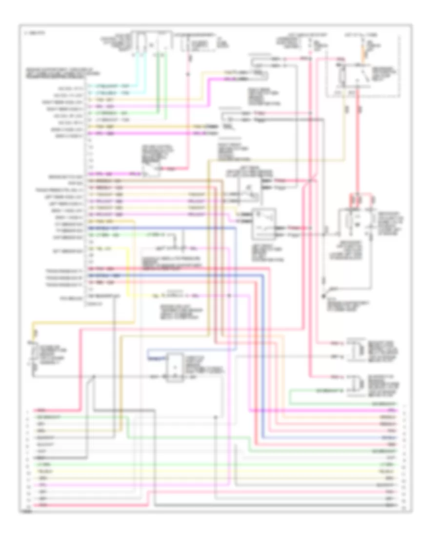
5.7L (VIN P), Engine Performance Wiring Diagrams (1 of 3) for Buick Roadmaster Estate Wagon 1996
 https://portal-diagnostov.com/license.html
Automotive Electricians Portal FZCO
Automotive Electricians Portal FZCO
https://portal-diagnostov.com/license.html
https://portal-diagnostov.com/license.html
Automotive Electricians Portal FZCO
Automotive Electricians Portal FZCO
List of elements for 5.7L (VIN P), Engine Performance Wiring Diagrams (1 of 3) for Buick Roadmaster Estate Wagon 1996:
- high res
- (engine compartment, forward of left wheelhouse, under air cleaner) powertrain control module
- 5 volts ref
- A ign
- A/c clutch status
- A/c request sig
- A/c system
- A/c system (compressor relay)
- A/c system (coolant fan relays)
- Air pump relay ctrl
- Battery
- C sig
- C 1995 vftc
- C pnk
- Ckp sensor sig
- Coil
- Conn c1
- Conn c2
- Crankshaft position sensor (left of a/c compressor)
- Cruise control, speedo, radio, warning alarm & p.s. ctrl module
- Dist ignition feed
- Dist ref low sig
- Distributor
- Egr solenoid ctrl
- Eng oil level sens sig
- Engine oil level sensor (left side of engine oil pan)
- Evap sol. diag. switch
- Evaporator emission canister purge vacuum switch (top of engine, right side of fuel injector no. 2)
- F/p fuse #2 15a
- From pcm
- Fuel enable sig
- Fuel inj fuse #6 10a
- Fuel inj fuse #9 10a
- Fuel injector #1
- Fuel injector #2
- Fuel injector #3
- Fuel injector #4
- Fuel injector #5
- Fuel injector #6
- Fuel injector #7
- Fuel injector #8
- Fuel pump relay ctrl
- G110 (engine compartment, on front of left cylinder head)
- High resolution sig
- Hot at all times
- Hot in run or start
- Hot in run, bulb test or start
- Idle speed control power steering pressure switch (in power steering line, near power unit)
- Ign
- Ignition
- Ignition ctrl
- Inj #1 ctrl
- Inj #2 ctrl
- Inj #3 ctrl
- Inj #4 ctrl
- Inj #5 ctrl
- Inj #6 ctrl
- Inj #7 ctrl
- Inj #8 ctrl
- Instrument cluster system
- Interface circuit
- Low oil ind ctrl
- Low res
- Low resolution sig
- Maf sensor sig
- Mass air flow sensor (between air cleaner and intake resonator)
- Optical sensor
- Pcm ground
- Pcm/ign fuse #5 10a
- Pnk
- Pri cool fan rel ctrl
- Psp switch in
- Red
- Ref low
- Sec cool fan rel ctrl
- Sensor ground
- Spark plugs
- Tach. sig
- Tcc temp switch (in trans. cooler inlet pipe)
- Tcc temp switch sig
- Theft deterrent module (left of brake pedal bracket)
- To evaporator emission canister purge vacuum switch
- Trans 1-2 shift ctrl
- Trans 2-3 shift ctrl
- Trans 3-2 shift ctrl
- Under- hood electrical center
- Vehicle speed sensor (right rear of transmission) b
- Vss ground
- Vss out
- Vss signal
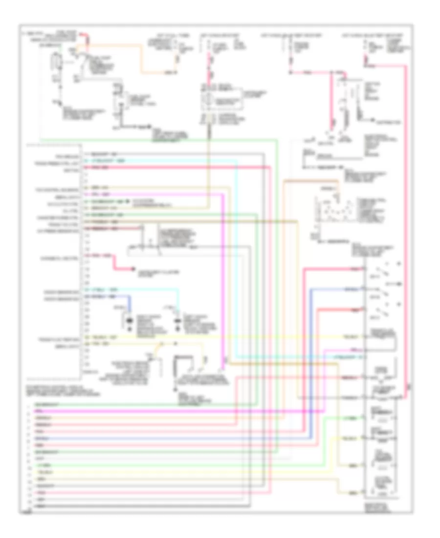
5.7L (VIN P), Engine Performance Wiring Diagrams (2 of 3) for Buick Roadmaster Estate Wagon 1996
 https://portal-diagnostov.com/license.html
Automotive Electricians Portal FZCO
Automotive Electricians Portal FZCO
https://portal-diagnostov.com/license.html
https://portal-diagnostov.com/license.html
Automotive Electricians Portal FZCO
Automotive Electricians Portal FZCOList of elements for 5.7L (VIN P), Engine Performance Wiring Diagrams (2 of 3) for Buick Roadmaster Estate Wagon 1996:
- (engine compartment, forward of left wheelhouse, under air cleaner) powertrain control module
- Air fuse #3 25a
- B10
- Bank 1 h02s low
- Bank 1 ho2s hi
- Bank 2 ho2s hi
- Bank 2 ho2s low
- Brake switch sig
- C 1995 vftc
- C pnk
- C10
- Chi body fuse #13 10a
- Conn c3
- Cruise control release switch (attached to brake pedal bracket)
- Ect sensor sig
- Emi fuse #4 20a
- Engine coolant temperature sensor (front of engine, below water pump)
- Evaporative emission canister purge solenoid valve (top of engine, behind inj #4)
- Exhaust gas recirulation control valve relay solenoid (top of engine, behind inj #7)
- G110 (engine compartment, on front of left cylinder head)
- Hot at all times
- Hot in run or start
- I/p fuse block
- Iac coil "a" hi
- Iac coil "a" low
- Iac coil "b" hi
- Iac coil "b" low
- Iat sensor sig
- Idle air control valve (attached to throttle body)
- Intake air temperature sensor (air cleaner assembly)
- Left front heated oxygen sensor (in left converter pipe)
- Left rear heated oxygen sensor (in left converter pipe)
- Left rear ho2s hi
- Left rear ho2s low
- Manifold absolute pressure sensor (front of engine compartment, above water pump)
- Map sensor sig
- Nca
- Pcm ground
- Pnk
- Pnp sig
- Red
- Red a
- Red b
- Right front heated oxygen sensor (in right converter pipe)
- Right rear heated oxygen sensor (in right converter pipe)
- Right rear ho2s hi
- Right rear ho2s low
- Secondary air injection (air) pump (lower left side of engine block)
- Secondary air injection bleed valve solenoid (lower left of engine)
- Secondary air injector (air) pump relay
- Tan
- Tan b
- Throttle position sensor (attached to right side throttle body)
- Tp sensor sig
- Trans press ctrl sol hi
- Trans range sig "a"
- Trans range sig "b"
- Trans range sig "c"
- Underhood electrical center
5.7L (VIN P), Engine Performance Wiring Diagrams (3 of 3) for Buick Roadmaster Estate Wagon 1996
 https://portal-diagnostov.com/license.html
Automotive Electricians Portal FZCO
Automotive Electricians Portal FZCO
https://portal-diagnostov.com/license.html
https://portal-diagnostov.com/license.html
Automotive Electricians Portal FZCO
Automotive Electricians Portal FZCOList of elements for 5.7L (VIN P), Engine Performance Wiring Diagrams (3 of 3) for Buick Roadmaster Estate Wagon 1996:
- (attached to i/p carrier, right of steering column)
- (buick) (chevy)
- (caprice) (roadmaster) (impala ss)
- 3-2 ctrl solenoid (pwm)
- A/c clutch ctrl
- A/c press sensor sig
- A/c refrigerant pressure sensor (in hi pressure line, above right wheelhouse)
- A/c system (compressor relay)
- C 1995 vftc
- C1 c2 c1
- C2 c1
- Canister purge ctrl
- Change oil ind ctrl
- Coil driver
- Conn c4
- Data link connector
- Distributor
- E11
- Electronic brake control module (left side of engine compartment, part of brake pressure modulator valve)
- Electronic controlled transmission
- Electronic ignition control module (front of engine)
- Emi fuse #4 20a
- F/p fuse #2 15a
- F10
- F11
- Force motor
- Fuel pump prim connector (near a/c accumulator)
- Fuel pump relay (underhood electrical center)
- Fuel pump/ sender (in fuel tank)
- G110 (engine compartment, on front of left cylinder head)
- G203 (base of left "a" pillar, behind kick panel)
- G402 (left rear wheel- house, in luggage compartment)
- Ground
- Hot at all times
- Hot in run or start
- Hot in run, bulb test or start
- I/p fuse block
- I/p indc fuse #11 10a
- Ign
- Ign ctrl
- Ignition
- Ignition coil (front of engine)
- Instrument cluster
- Instrument cluster system
- Knock sensor sig
- Left knock sensor (left of engine block, forward of starter)
- Malfunction indicator
- Mil ctrl
- Nca
- Park/neutral position switch (under front console, attached to a/t control)
- Pcm ground
- Pcm/ign fuse #5 10a
- Pnk
- Pnk a
- Pnk a9 b2
- Pnk e
- Powertrain control module (engine compartment, forward of left wheelhouse, under air cleaner)
- Red
- Right knock sensor (right of engine block, below exhaust manifold)
- Serial data
- Shift solenoid a
- Shift solenoid b
- Sw a
- Sw b
- Sw c
- Tan
- Tcc control solenoid
- Tcc enable solenoid
- Trans fluid temp sensor
- Trans fluid temp sig
- Trans press ctrl low
- Trans tcc ctrl
- Under- hood electrical center
- Underhood electrical center

 Čeština
 Dansk
Dansk Deutsch
 Ελληνικά
 English
 English
 Español
 Suomi
Suomi Français
 Français
 עברית
עברית Hrvatski
 Magyar
 Italiano
 한국어
한국어 Nederlands
 Polski
 Português
 Português
 Română
 Русский
 Slovenčina
 Slovenščina
 Svenska
 Türkçe
 中文 (中国)
