GROUND DISTRIBUTION
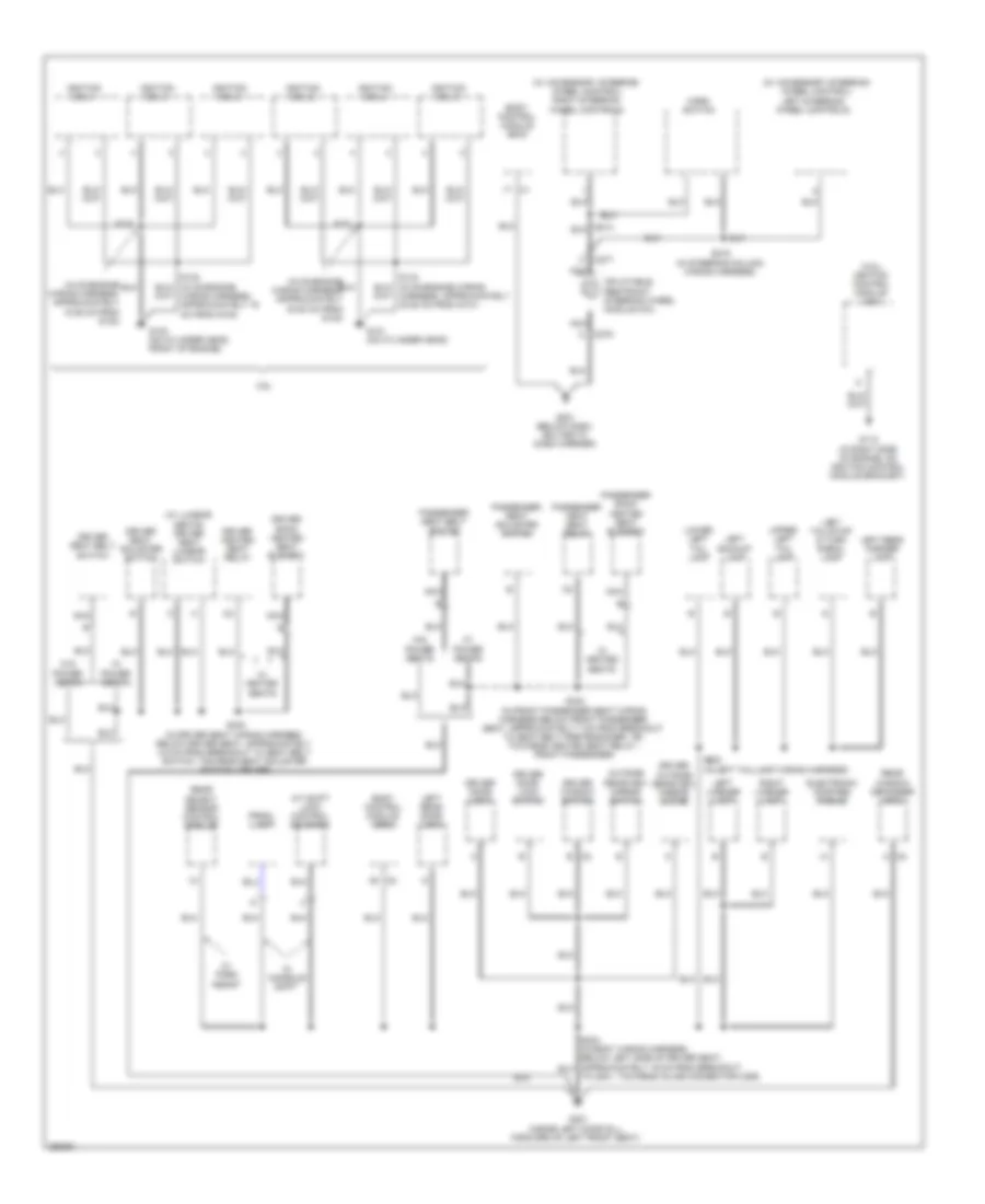
Ground Distribution Wiring Diagram (1 of 3) for Buick Allure CXL 2007
 https://portal-diagnostov.com/license.html
Automotive Electricians Portal FZCO
Automotive Electricians Portal FZCO
https://portal-diagnostov.com/license.html
https://portal-diagnostov.com/license.html
Automotive Electricians Portal FZCO
Automotive Electricians Portal FZCO
List of elements for Ground Distribution Wiring Diagram (1 of 3) for Buick Allure CXL 2007:
- (3.6l) engine control module (ecm)
- (mounted to right strut tower) underhood fuse block
- (sulev) secondary air injection (air) control solenoid valve/ pressure sensor bank 2
- 3.6l
- 3.8l
- A/c clu diode
- A/c clutch diode
- A/c compressor clutch
- Approximately 20 cm from g115)
- Automatic transmission
- B b
- B11
- Battery
- Body control module (bcm)
- C100
- E15
- Electronic brake control module (ebcm)
- Engine oil level switch
- Engine oil pressure (eop) switch
- Except sulev
- Fan 2 relay 46
- Fuel pp relay 41
- G100 (in back of right headlamp on frame)
- G101 (left side of front end upper tie bar, in back of headlamp)
- G102 (3.6l: below right front strut tower) (3.8l: near battery)
- G103 (redundant ground from ecm to even bank cylinder head)
- G111 (3.6l: lower left front of engine, on transmission stud, near starter) (3.8l: lower left side of engine)
- G113 (lower left front of engine, on transmission stud, near starter)
- G115 (mounted to bank 1 cylinder head above exhaust manifold)
- G115 (on transmission stud, to right of starter)
- Hdm beam module 35
- Hood ajar switch
- Horn assembly
- Ign 1 relay 37
- Jumper wiring harness, approximately 5 cm from breakout to left park/turn signal lamp, toward left front fog lamp)
- K14
- Left front fog lamp
- Left front marker lamp
- Left front park/ turn signal lamp
- Left high beam headlamp
- Left low beam headlamp
- Mass air flow (maf)/ intake air temperature (iat) sensor
- Powertrain control module (pcm)
- Right cooling fan
- Right front fog lamp
- Right front marker lamp
- Right front park/ turn signal lamp
- Right high beam headlamp
- Right low beam headlamp
- S101 (in engine wiring harness, in left front of engine compt, approximately 5 cm from breakout to pcm, towards g113)
- S102 (in engine wiring harness. top of engine, approximately 5 cm from breakout to throttle actuator control (tac) module, towards pcm)
- S111
- S112 (in forward lamp harness, approximately 19 cm from left front headlamp assembly)
- S116
- S124 (in forward lamp wiring harness, behind right headlamp, approximately 5 cm from breakout to c142, towards horn assembly)
- S127 (in left headlamp wiring harness)
- Secondary air injection (air) pump (sulev)
- Sulev
- Throttle actuator control (tac) module
- Transmission control module (tcm)
- Transmission internal mode switch (ims)
- Windshield washer fluid level switch
- Windshield washer fluid pump
- Wiper relay 45
- Wiring harness)
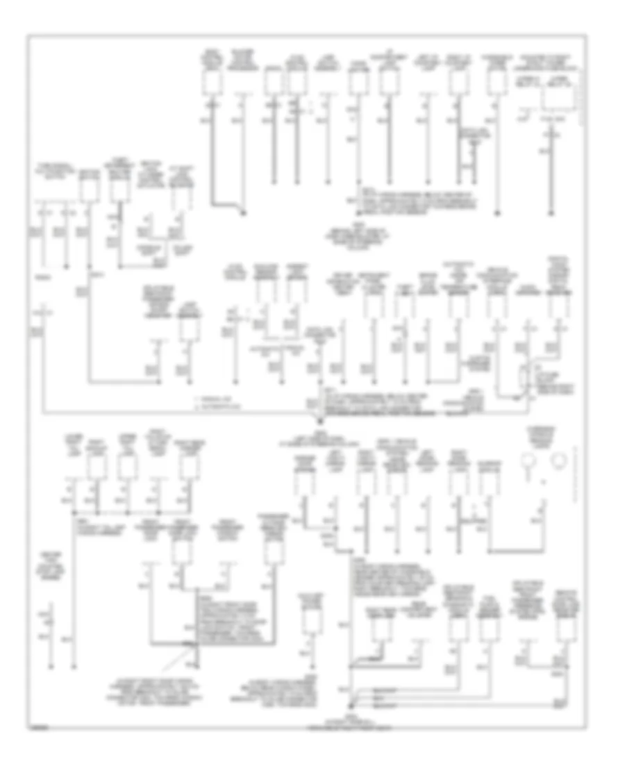
Ground Distribution Wiring Diagram (2 of 3) for Buick Allure CXL 2007
 https://portal-diagnostov.com/license.html
Automotive Electricians Portal FZCO
Automotive Electricians Portal FZCO
https://portal-diagnostov.com/license.html
https://portal-diagnostov.com/license.html
Automotive Electricians Portal FZCO
Automotive Electricians Portal FZCOList of elements for Ground Distribution Wiring Diagram (2 of 3) for Buick Allure CXL 2007:
- (3.8l) ignition control module (icm)
- (in on-engine wiring harness, approximately 15.25 cm from g130)
- (in on-engine wiring harness, approximately 30.50 cm from g130)
- (w/ accessory steering wheel control)
- (w/ accessory steering wheel control) right steering wheel controls
- (w/ lumbar seats) driver seat lumbar switch
- 3.6l
- A c2
- A/t shift lock control solenoid
- B c2
- Body control module (bcm)
- C275
- C277
- Driver back heated seat element
- Driver door lock
- Driver door lock switch
- Driver heated seat relay
- Driver outside rearview mirror motor
- Driver seat adjuster switch
- Driver seat belt switch
- Driver window switch
- Electronic compass module
- G112 (in right side of engine, on ignition control module bracket)
- G130 (on cylinder head, front of engine)
- G131 (on cylinder head)
- G201 (below dash, bolted to dash carrier)
- G301 (inside left door sill, forward of left front seat)
- Horn switch
- Ignition coil 1
- Ignition coil 2
- Ignition coil 3
- Ignition coil 4
- Ignition coil 5
- Ignition coil 6
- Inflatable restraint steering wheel module coil
- Left backup lamp
- Left license lamp
- Left rear door lock
- Left rear marker lamp
- Left steering wheel controls
- Left tail/stop & turn signal lamp
- Lower left tail lamp
- Nca
- Outside rearview mirror switch
- Passenger back heated seat element
- Passenger heat seat relay
- Passenger seat adjuster switch
- Passenger seat belt switch
- Prndl lamp
- Rear object sensor control module
- Rear window defogger grid
- Right license lamp
- S130
- S131
- S215 (in steering column wiring harness)
- S330 (in driver seat wiring harness, below driver seat, approximately 4.5 cm from breakout to seat belt switch, towards seat adjuster switch - driver)
- S333 (in front passenger seat wiring harness below front passenger seat, approximately 7 cm from breakout to seat belt pretensioner - rf, towards heated seat relay - front passenger)
- S900 (in left taillamp wiring harness)
- To g301, towards inline connector c355)
- Upper left tail lamp
- W/ console shift
- W/ heated seats
- W/ park assist
- W/ power seats
- W/o power seats
Ground Distribution Wiring Diagram (3 of 3) for Buick Allure CXL 2007
 https://portal-diagnostov.com/license.html
Automotive Electricians Portal FZCO
Automotive Electricians Portal FZCO
https://portal-diagnostov.com/license.html
https://portal-diagnostov.com/license.html
Automotive Electricians Portal FZCO
Automotive Electricians Portal FZCOList of elements for Ground Distribution Wiring Diagram (3 of 3) for Buick Allure CXL 2007:
- (automatic a/c) inside air temperature sensor
- (digital audio system s-band) digital radio receiver
- (gps 1 vehicle communication system) inside rearview mirror
- (in i/p wiring harness, below center of dash, approximately 10 cm from breakout to data link connector towards brake pedal position sensor)
- (in i/p wiring harness, below center of dash, approximately 5 cm from breakout to data link connector towards brake pedal position sensor)
- (in right front door wiring harness, approximately 25.5 cm from breakout to inline connector c304, towards window motor - front passenger)
- (mounted to right strut tower) underhood fuse block
- A/t shift lock control solenoid
- A12 c1
- A15
- A6 c1
- Ambient light sensor
- Audio amplifier
- Automatic a/c
- Auxiliary power outlet
- B8 c1
- Blower motor control processor
- Body control module (bcm)
- Brake fluid level switch
- C1 b5
- Center high mounted stop lamp (chmsl)
- Cigar lighter
- Column shift
- Console shift
- Custom 9 speaker system
- D c1
- Data link connector (dlc)
- Driver information center (dic)
- E15
- F c1
- F14
- F7 c2
- Front passenger door lock
- Front passenger door lock switch
- Front passenger window switch
- Fuel pump & sender assembly
- G c2
- G200 (behind left side of dash knee bolster, at base of steering column)
- G202 (left side of dash, at base of steering column)
- G302 (in right door sill, forward of right front seat)
- Garage door opener
- Gps 1 vehicle communication system
- Hvac control module
- I/p compartment lamp switch
- I/p fuse block (behind right side of dash)
- If equipped
- Ignition lock cylinder control actuator
- Ignition switch
- Inflatable restraint front passenger presence system (pps) module
- Inflatable restraint passenger air bag on/off indicator
- Inflatable restraint sensing & diagnostic module (sdm)
- Instrument panel cluster (ipc)
- Lamp switch assembly
- Left dome/ reading lamp
- Left i/p courtesy lamp
- Left vanity mirror lamp
- Lower right tail lamp
- Manual a/c
- Nca
- Overhead console reading lamps
- Passenger outside rearview mirror motor
- Passenger, towards inline connector c304)
- Radio
- Rear compartment lid latch
- Remote control door lock receiver (rcdlr)
- Right backup lamp
- Right dome/ reading lamp
- Right i/p courtesy lamp
- Right rear door lock
- Right rear marker lamp
- Right tail/stop & turn signal lamp
- Right vanity mirror lamp
- S211
- S213
- S214
- S300
- S309
- S390 (in roof wiring harness, near center of windshield header approximately 20 cm from courtesy/reading lamp - right breakout, towards inside rearview mirror)
- S406 (in body wiring harness, below rear window panel, approximately 9 cm from breakout to inline connector c356, towards g302)
- S604
- S901 (in right taillamp wiring harness)
- Sunload sensor assembly
- Sunroof module
- Theft deterrent exciter module
- Theft led
- Turn signal/ multifunction switch
- Upper right tail lamp
- Vehicle communication interface module (vcim)
- Windshield wiper motor
- Wiper hi relay 44
- Wiper relay 45

 Čeština
 Dansk
Dansk Deutsch
 Ελληνικά
 English
 English
 Español
 Suomi
Suomi Français
 Français
 עברית
עברית Hrvatski
 Magyar
 Italiano
 한국어
한국어 Nederlands
 Polski
 Português
 Português
 Română
 Русский
 Slovenčina
 Slovenščina
 Svenska
 Türkçe
 中文 (中国)
