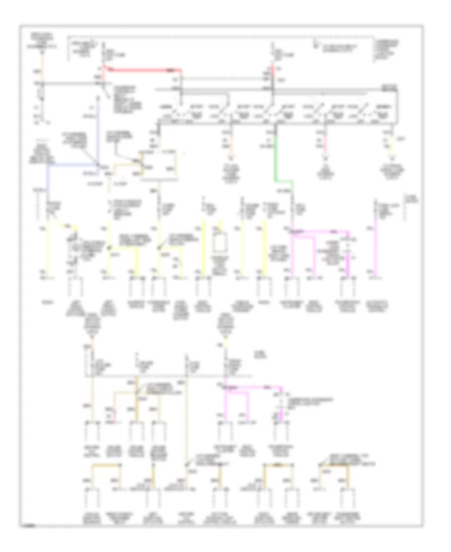
POWER DISTRIBUTION
Power Distribution Wiring Diagram (1 of 3) for Buick Century Limited 1998
 https://portal-diagnostov.com/license.html
Automotive Electricians Portal FZCO
Automotive Electricians Portal FZCO
https://portal-diagnostov.com/license.html
https://portal-diagnostov.com/license.html
Automotive Electricians Portal FZCO
Automotive Electricians Portal FZCO
List of elements for Power Distribution Wiring Diagram (1 of 3) for Buick Century Limited 1998:
- (body harn, right floor near passen- ger's seat)
- (i/p harness, 21 cm from bulkhead grommet) s275
- (i/p harness, right of steering column)
- A/c clu fuse 10a
- A/c clu relay
- Abs-bcm fuse 10a
- Accessory power receptacle
- B (century) (regal) c
- B12
- Bat 1 maxi fuse 60a
- Bat 2 maxi fuse 60a
- Bat 3 maxi fuse 60a
- Battery
- Blower motor control module
- Blower motor resistor
- Body control module
- C12
- C201
- C60/cj3
- Cd changer fuse 10a
- Century
- Cigar lighter
- Cigar ltr fuse 20a
- Cj2
- Cool fan 1 maxi fuse 40a
- Cool fan 1 relay
- Cool fan 2 maxi fuse 30a
- Cool fan 2 relay
- Cool fan 3 relay
- Crank maxi fuse 40a
- Crank relay
- Data link connector
- Daytime running lamp control module
- Door lock relay
- Door locks fuse 20a
- Driver seat heater control module
- Driver's seat adjuster switch
- Ecm fuse 10a
- Electronic brake control module/ electronic brake traction control module
- Electronic brake control relay
- F/pmp fuse 15a
- F/pmp relay
- From a remote battery stud (diagram 1 of 3)
- From bat 2 maxi fuse (diagram 1 of 3)
- Fuse block
- Fusible link (10 ga-rust)
- G201 (behind right side of dash)
- Gen fuse 10a
- Generator
- Hazard fuse 15a
- Hdlp l fuse 15a
- Hdlp r fuse 15a
- Headlamp switch
- Heater- a/c control
- High blower fuse 25a
- Horn fuse 15a
- Horn relay
- Inadv power bus fuse 15a
- Instrument cluster
- L heated seat fuse 15a
- Left headlamp
- Lp park fuse 20a
- Mobile telephone amplifier
- Mobile telephone handset
- Nca
- Outside remote control rearview mirror switch
- Passenger seat heater control module
- Passenger's seat adjuster switch
- Power mirrors fuse 10a
- Power seats circuit breaker 30a
- Powertrain control module
- R heated seat fuse 15a
- R/cmpt rel fuse 7.5a
- Radio
- Radio- hvac fuse 15a
- Rear defogger circuit breaker 30a
- Rear window defogger relay
- Red
- Regal
- Remote battery stud
- Remote cd changer
- Remote control door lock receiver
- Right headlamp
- S202
- S269 (i/p harness, near blower motor)
- S319
- S335
- S336
- Starter
- Stop lamp switch
- Stop lamps fuse 15a
- To accessory time delay relay (diagram 2 of 3)
- To hdlp l fuse (diagram 1 of 3)
- To high blower fuse (diagram 1 of 3)
- To ign 2 maxi fuse (diagram 2 of 3)
- Transaxle range switch
- Turn signal switch
- Underhood accessory wiring junction block
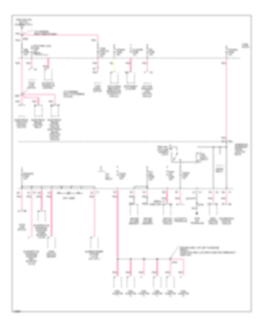
Power Distribution Wiring Diagram (2 of 3) for Buick Century Limited 1998
 https://portal-diagnostov.com/license.html
Automotive Electricians Portal FZCO
Automotive Electricians Portal FZCO
https://portal-diagnostov.com/license.html
https://portal-diagnostov.com/license.html
Automotive Electricians Portal FZCO
Automotive Electricians Portal FZCOList of elements for Power Distribution Wiring Diagram (2 of 3) for Buick Century Limited 1998:
- (body harness, top of floor tunnel between front seats)
- (body harness, under left side of rear seat)
- (cj2)
- (cj2) (c60/cj3)
- (i/p harn, behind right side of dash)
- (i/p harness, 4 cm from radio breakout)
- (i/p harness, near blower motor)
- (i/p harness, near steering column)
- (i/p harness, right side of steering column)
- A nca
- Accessory time delay relay (behind i/p compt, under- side of cross- car beam)
- Accy
- Automatic transaxle control
- Bcm fuse 10a
- Body control module
- Body control module (below left side of dash)
- Bulb test
- C13
- C201
- C5 c (c60/cj3)
- Console compt lamp switch (regal)
- Crank signal fuse 10a
- Cruise control module
- Cruise control release switch
- Cruise control switch
- Cruise fuse 10a
- Daytime running lamp control module
- Driver seat heater switch
- From gen d fuse (diagram 1 of 3)
- From ignition switch (diagram 2 of 3)
- From inadv power bus fuse (diagram 1 of 3)
- Fuse block
- Heater- a/c control
- Hvac fuse 10a
- Ign 0 fuse 10a
- Ign1 maxi fuse 30a
- Ign2 maxi fuse 40a
- Ignition switch
- Inflatable restraint steering wheel coil
- Inside rearview mirror
- Instrument cluster
- Left electric actuator
- Left front window switch
- Left radio control switches
- Lock
- Low blower fuse 20a
- Mobile telephone handset
- Nca
- Nca a
- Off
- Park lock fuse (regal) 10a
- Passenger seat heater switch
- Pnk
- Power drop fuse 10a
- Powertrain control module
- Pwr windows pwr sunroof circuit breaker 30a
- Radio
- Radio fuse (w/o rap) 2a
- Radio fuse 2a
- Rear window defogger relay
- Red
- Right electric actuator
- Run
- S220
- S233
- S234
- S240
- S249
- S263
- S270
- S323
- S410
- Start
- Sunroof module
- To crank signal fuse (diagram 2 of 3)
- To ign main relay (diagram 3 of 3)
- To low blower fuse (diagram 2 of 3)
- To s228 (diagram 3 of 3)
- Under- hood accessory wiring junction block
- Underhood accessory wiring junction block
- Underhood accessory wiring junction box
- Vacuum electric solenoid
- W/ rap
- W/o rap
- Wind- shield wiper/ washer switch
- Windshield wiper motor
- Wiper fuse 25a
Power Distribution Wiring Diagram (3 of 3) for Buick Century Limited 1998
 https://portal-diagnostov.com/license.html
Automotive Electricians Portal FZCO
Automotive Electricians Portal FZCO
https://portal-diagnostov.com/license.html
https://portal-diagnostov.com/license.html
Automotive Electricians Portal FZCO
Automotive Electricians Portal FZCOList of elements for Power Distribution Wiring Diagram (3 of 3) for Buick Century Limited 1998:
- (century)
- (engine harn, top left of engine) (regal) (injector harn, 2 cm from injector 2 breakout) (century)
- (i/p harness, right of steering column)
- (i/p harness, right side of dash)
- (not used)
- (regal)
- A/c clu relay
- Abs fuse 10a
- Air bag fuse 15a
- Automatic transaxle
- Automatic transaxle control
- B12
- Body control module
- Btsi park lock fuse 10a (regal)
- C12
- Cluster fuse 10a
- Crank relay
- Daytime runnning lamp control module
- Drl fuse 10a
- Electronic brake control module/ electronic brake traction control module
- Electronic brake control relay
- Electronic traction control switch
- Elek ign fuse 15a
- Eng emis fuse 10a
- Evaporative emissions canister purge solenoid valve
- Evaporative emissions canister vent solenoid valve
- F/injr fuse 15a
- From ign1 e maxi fuse (diagram 2 of 3)
- From ignition switch (diagram 2 of 3)
- Fuel injector
- Fuse block
- G129 (on transaxle)
- Heated oxygen sensor 1
- Heated oxygen sensor 2
- Ign main relay
- Ignition control module
- Inflatable restraint sensing and diagnostic module
- Instrument cluster
- Mass air flow sensor
- Nca
- Oxy sen fuse 15a
- Pcm-bcm fuse 10a
- Pnk
- Powertrain control module
- S106
- S109
- S228
- S287
- Stop lamp switch
- Supercharger bypass valve (3.8l vin 1)
- Trans fuse 10a
- Turn signal switch
- Turn signals fuse 10a
- Underhood accessory wiring junction block

 Čeština
 Dansk
Dansk Deutsch
 Ελληνικά
 English
 English
 Español
 Suomi
Suomi Français
 Français
 עברית
עברית Hrvatski
 Magyar
 Italiano
 한국어
한국어 Nederlands
 Polski
 Português
 Português
 Română
 Русский
 Slovenčina
 Slovenščina
 Svenska
 Türkçe
 中文 (中国)
