ELECTRONIC POWER STEERING
Electronic Power Steering Wiring Diagram for Audi Q7 4.2 2010
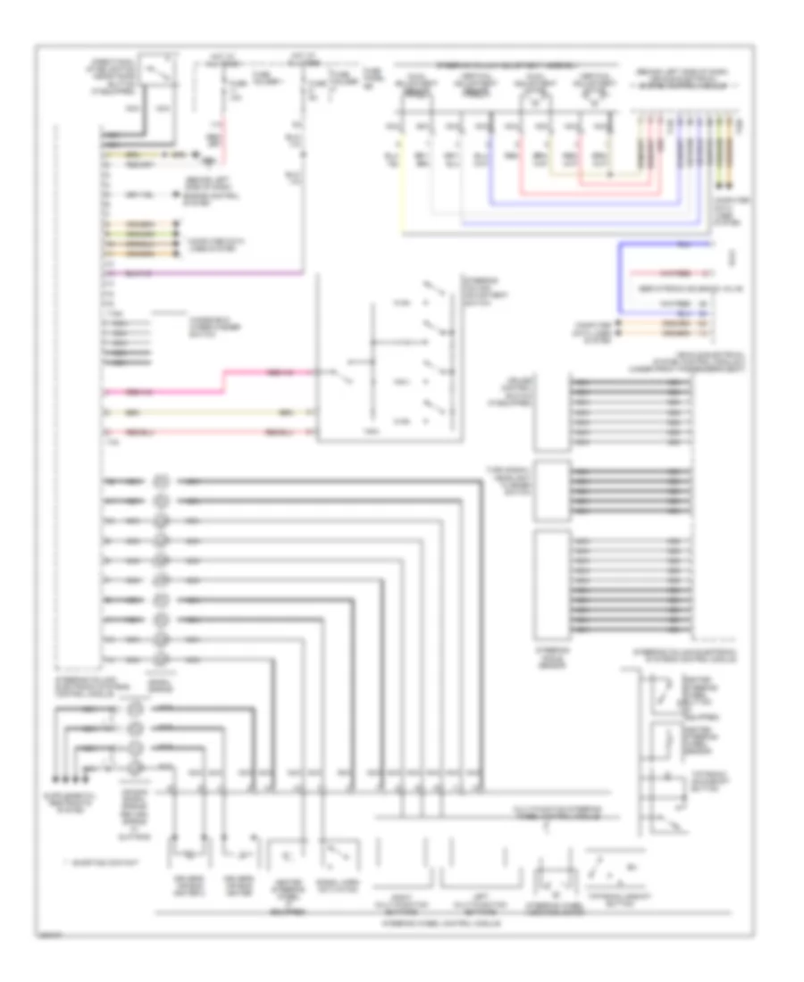
List of elements for Electronic Power Steering Wiring Diagram for Audi Q7 4.2 2010:
- (behind left side of dash)
- (behind left side of dash) vehicle electrical system control module
- 11a
- Air bag spiral spring/ return spring w/ slip ring
- Axial adjustment motor
- Axial adjustment sensor
- Computer data lines system
- Cruise control switch (if equipped)
- Directional stabilization assistance button (if equipped)
- Driver's air bag igniter
- Driver's air bag igniter 2
- Engine control system
- Fuse 10a
- Fuse 5a
- Fuse holder
- Fuse holder 1
- Fuse panel sb
- G664
- Heated steering wheel (if equipped)
- Heated steering wheel button (if equipped)
- Heated steering wheel sensor
- Hot at all times
- Left multi-function buttons
- Multi-function steering wheel control module
- Nca
- Red
- Right multi-function buttons
- Servotronic solenoid valve
- Shorting contact
- Signal horn activation
- Spiral spring
- Steering angle sensor
- Steering column adjustment assembly
- Steering column adjustment switch
- Steering column electronic systems control module
- Steering wheel control module
- Steering wheel vibration motor
- T12b
- T16a
- T32b
- T4a
- Tiptronic downshift button
- Tiptronic upshift button
- Turn signal/ headlight flasher switch
- Vehicle electrical system control module 2 (under front passenger's seat)
- Vertical adjustment motor
- Vertical adjustment sensor
- Windshield wiper/washer switch
 Čeština
 Dansk
Dansk Deutsch
 Ελληνικά
 English
 English
 Español
 Suomi
Suomi Français
 Français
 עברית
עברית Hrvatski
 Magyar
 Italiano
 한국어
한국어 Nederlands
 Polski
 Português
 Português
 Română
 Русский
 Slovenčina
 Slovenščina
 Svenska
 Türkçe
 中文 (中国)
 日本語
日本語