ENGINE PERFORMANCE
2.0L TURBO
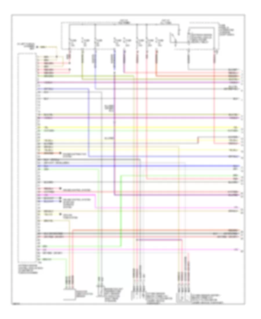
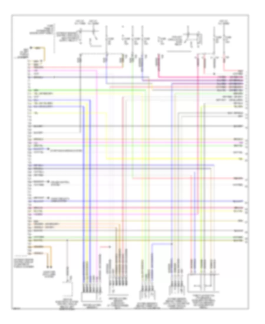
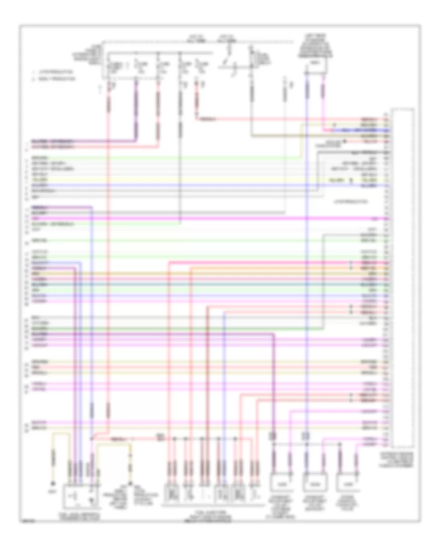
2.0L Turbo, Engine Performance Wiring Diagram, BPY (1 of 5) for Audi A3 2008
 https://portal-diagnostov.com/license.html
Automotive Electricians Portal FZCO
Automotive Electricians Portal FZCO
https://portal-diagnostov.com/license.html
https://portal-diagnostov.com/license.html
Automotive Electricians Portal FZCO
Automotive Electricians Portal FZCO
List of elements for 2.0L Turbo, Engine Performance Wiring Diagram, BPY (1 of 5) for Audi A3 2008:
- (in center of plenum chamber)
- (in left plenum chamber) g607
- (on intake air duct) mass air flow (maf) sensor
- Accelerator pedal position sensor 2 & throttle position (tp) sensor (at accelerator pedal)
- Charge air pressure sensor (in charge air pipe)
- Cooling fans system
- Cruise control system
- Engine coolant temperature (ect) sensor (right rear of engine)
- Fuse 10a
- Fuse 25a
- Fuse panel b (integrated in engine compt e-box)
- Fuse/ relay carrier
- Heated oxygen sensor (in exhaust, at turbocharger exit)
- Hot w/ ecm relay energized
- Late produ- ction
- Motronic engine control module (ecm)
- Nca
- Oxygen sensor behind three way catalytic convertor (under vehicle, in exhaust)
- T26
- T40
- T94
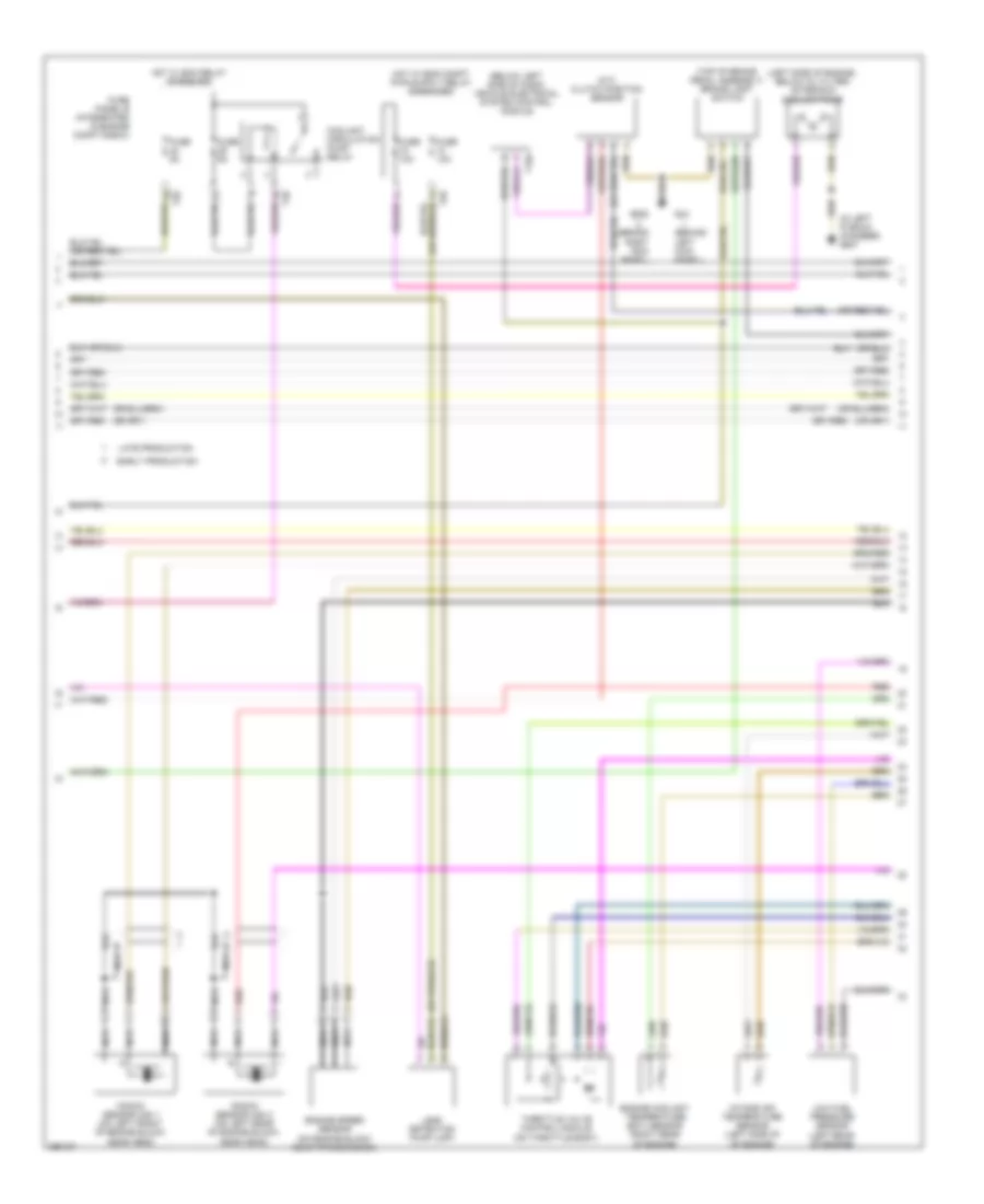
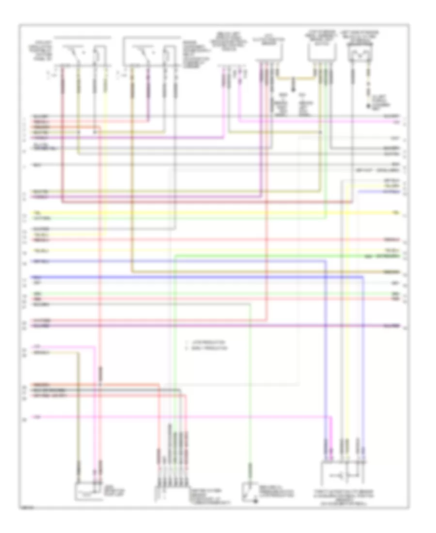
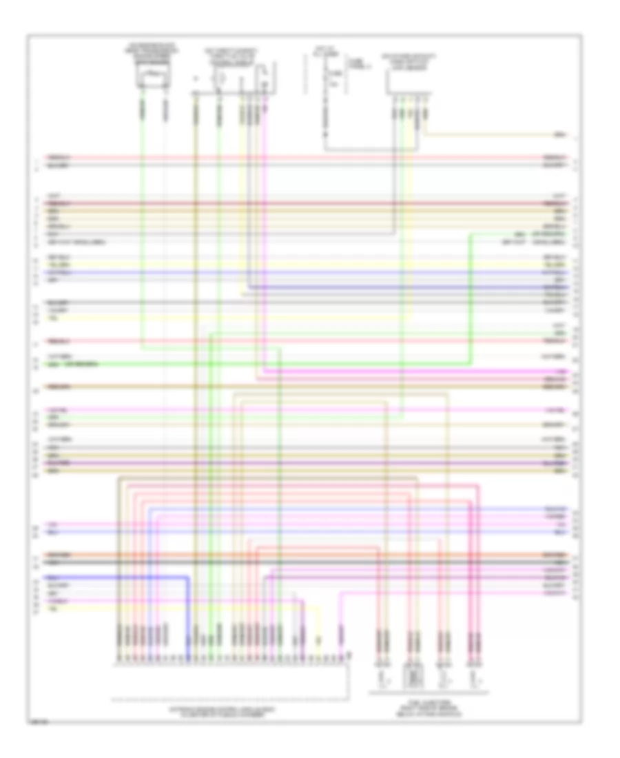
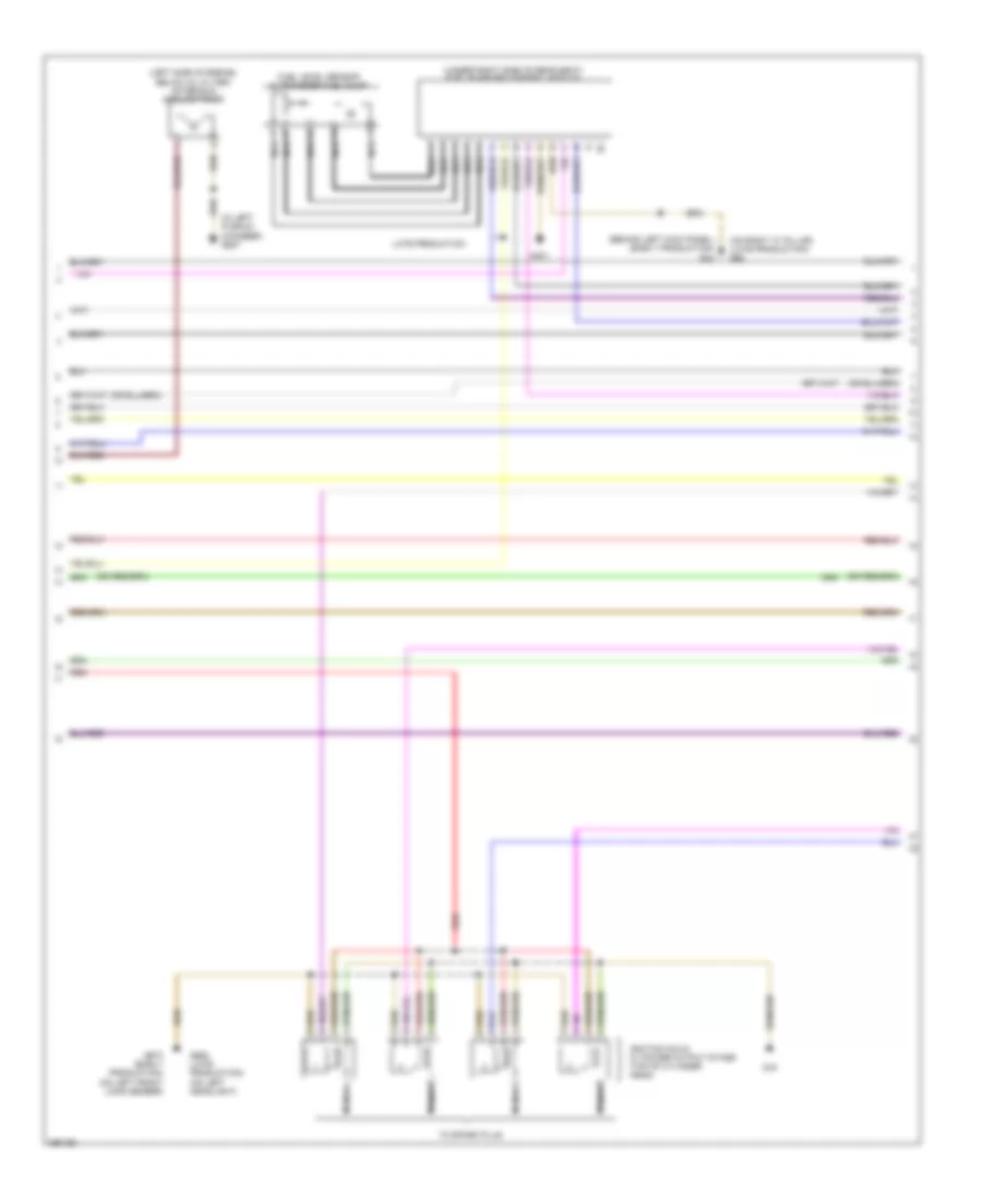
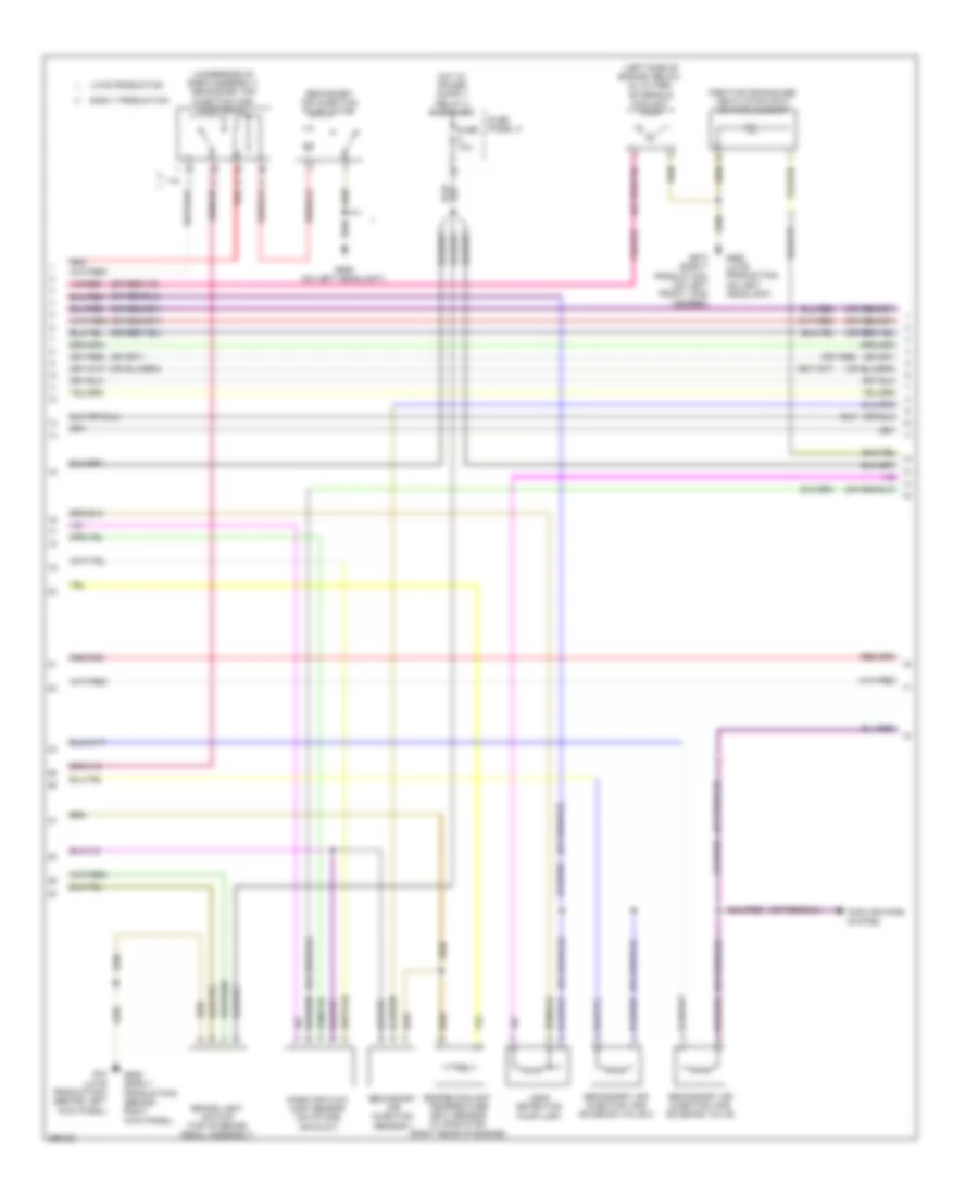
2.0L Turbo, Engine Performance Wiring Diagram, BPY (2 of 5) for Audi A3 2008
 https://portal-diagnostov.com/license.html
Automotive Electricians Portal FZCO
Automotive Electricians Portal FZCO
https://portal-diagnostov.com/license.html
https://portal-diagnostov.com/license.html
Automotive Electricians Portal FZCO
Automotive Electricians Portal FZCOList of elements for 2.0L Turbo, Engine Performance Wiring Diagram, BPY (2 of 5) for Audi A3 2008:
- (behind left kick panel)
- (behind right kick panel)
- (below left side of dash) vehicle electrical system control module
- (in left plenum chamber) g607
- (left side of engine, below oil filter) after-run coolant pump
- (m/t) clutch position sensor
- (top of brake pedal assembly) brake light switch
- Coolant circulation pump relay
- Early production
- Engine coolant temperature (ect) sensor (right rear of engine)
- Engine speed sensor (on engine block near transmission)
- Fuse 10a
- Fuse 5a
- Fuse panel b (integrated in engine compt e-box)
- G44
- G638
- Hot w/ ecm relay energized
- Intake air temperature sensor (left side of of engine)
- Knock sensor (ks) 1 (on left front of engine block, near head)
- Knock sensor (ks) 2 (on left rear of engine block, near head)
- Late production
- Leak detection pump (ldp)
- Low fuel pressure sensor (left rear of engine)
- Nca
- Red
- T16a
- T26
- T40
- Throttle valve control module (on throttle body)
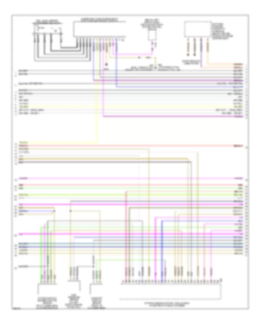
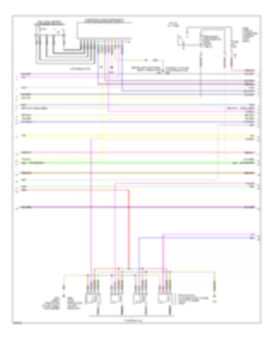
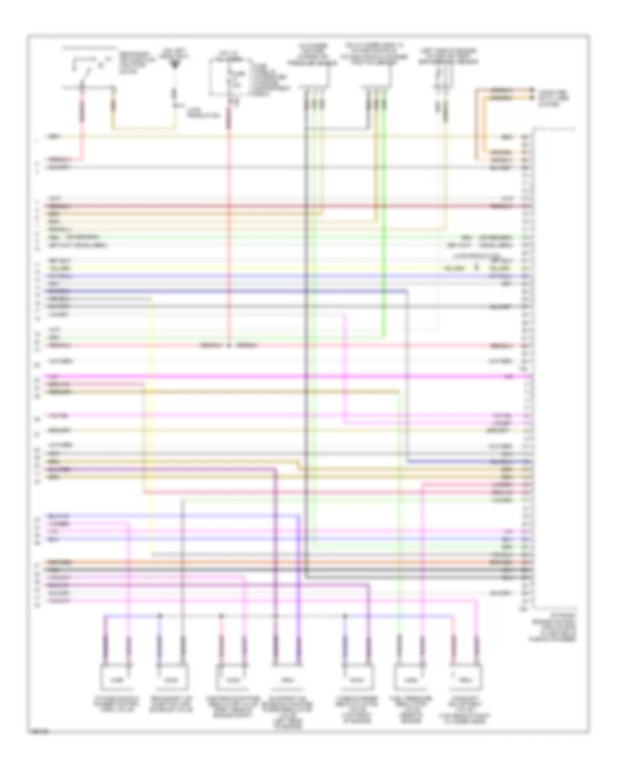
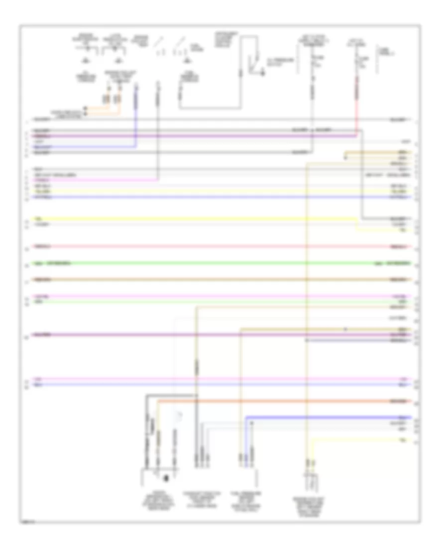
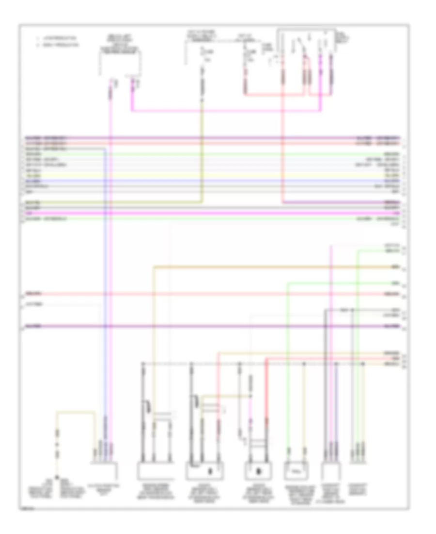
2.0L Turbo, Engine Performance Wiring Diagram, BPY (3 of 5) for Audi A3 2008
 https://portal-diagnostov.com/license.html
Automotive Electricians Portal FZCO
Automotive Electricians Portal FZCO
https://portal-diagnostov.com/license.html
https://portal-diagnostov.com/license.html
Automotive Electricians Portal FZCO
Automotive Electricians Portal FZCOList of elements for 2.0L Turbo, Engine Performance Wiring Diagram, BPY (3 of 5) for Audi A3 2008:
- (below left side of dash) vehicle electrical system control module
- (under right side of rear seat) fuel pump (fp) control module
- Camshaft position sensor (front of cylinder head)
- Computer data lines system
- Data bus on-board diagnostic interface (behind center console storage compartment)
- Fuel level sensor & transfer fuel pump
- Fuel pressure sensor (on left side of engine, in fuel rail)
- G401
- G44 (early production) (behind left kick panel)
- G62 (late production) (on right "c" pillar)
- Intake manifold runner position sensor (on cylinder head, in intake manifold)
- Motronic engine control module (ecm) (in center of plenum chamber)
- Nca
- Red
- T11b
- T60
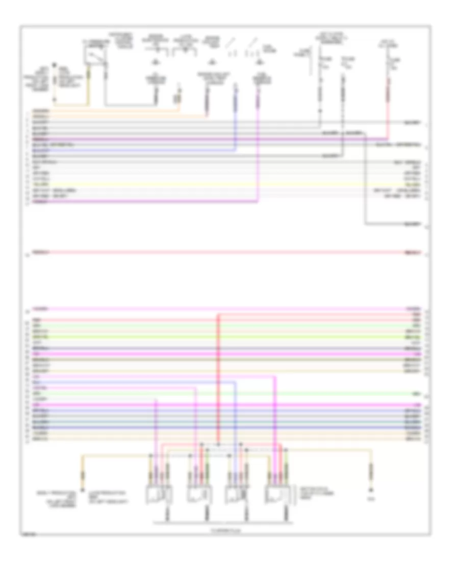
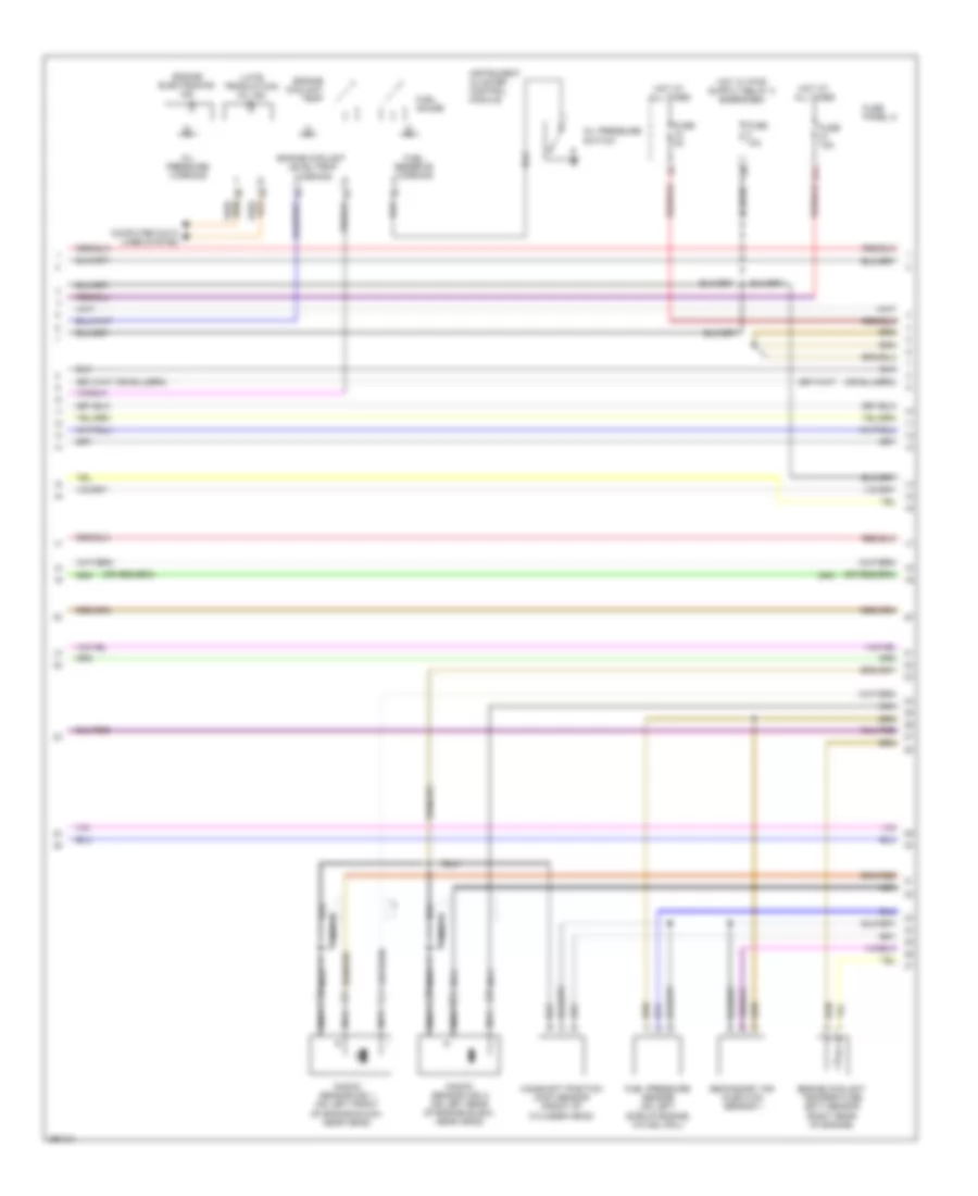
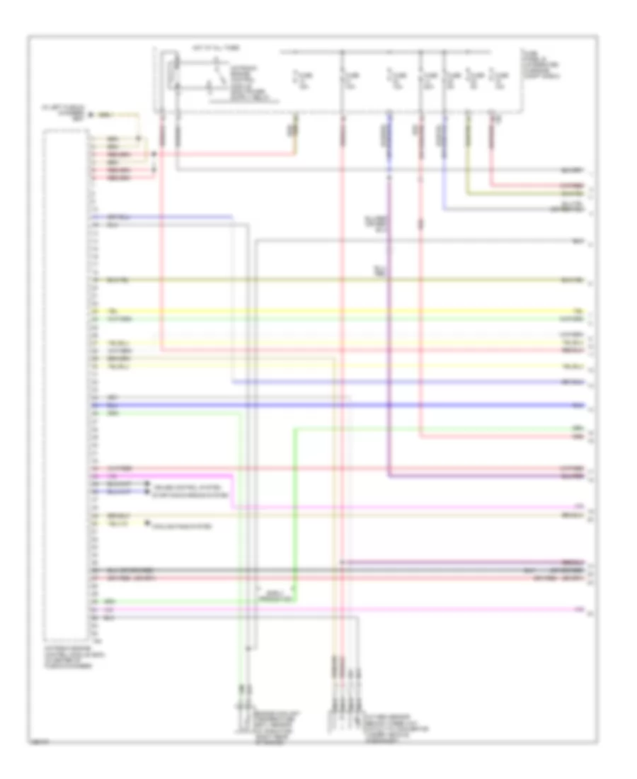
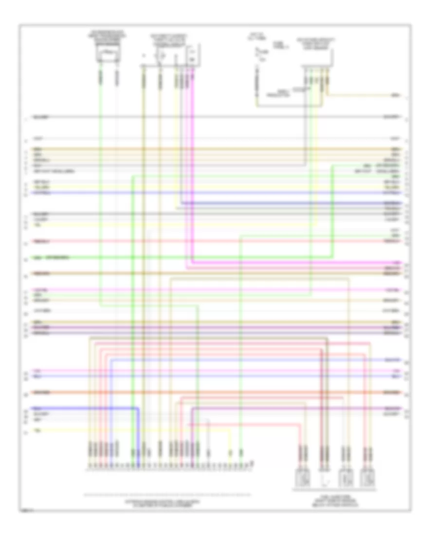
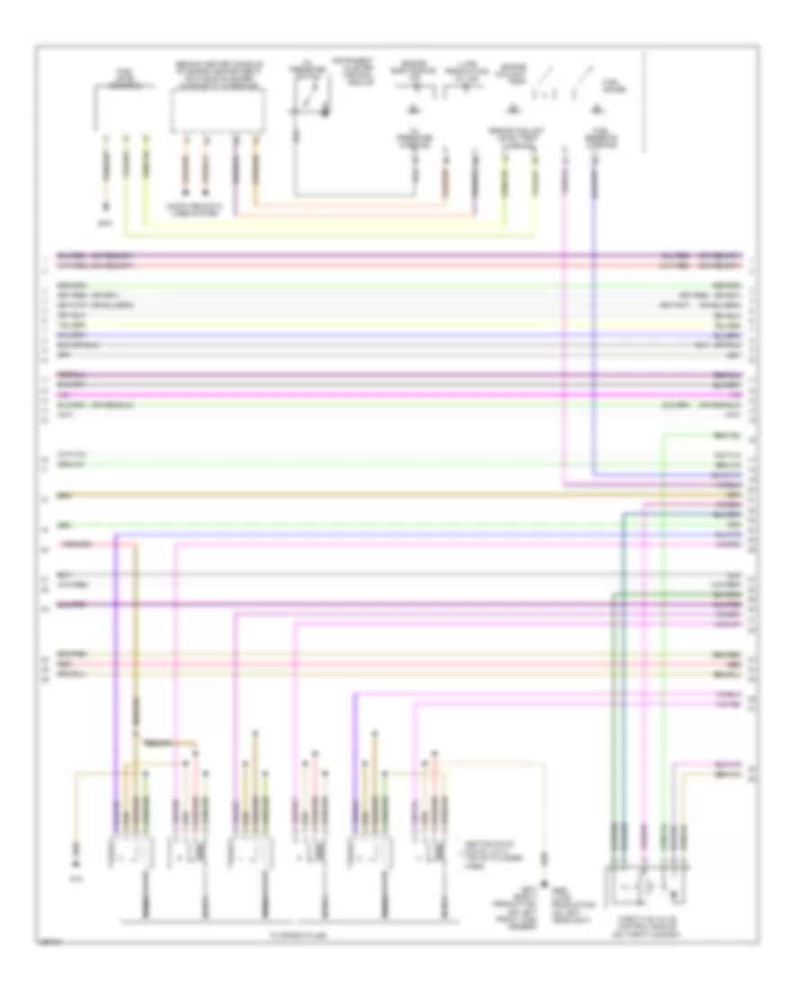
2.0L Turbo, Engine Performance Wiring Diagram, BPY (4 of 5) for Audi A3 2008
 https://portal-diagnostov.com/license.html
Automotive Electricians Portal FZCO
Automotive Electricians Portal FZCO
https://portal-diagnostov.com/license.html
https://portal-diagnostov.com/license.html
Automotive Electricians Portal FZCO
Automotive Electricians Portal FZCOList of elements for 2.0L Turbo, Engine Performance Wiring Diagram, BPY (4 of 5) for Audi A3 2008:
- (early production) g673 (on left front long member)
- (late production) g655 (on left headlight)
- (late production) mil ind
- 27a
- Engine coolant level/temp warning
- Engine coolant temp
- Engine electronics ind
- Fuel gauge
- Fuel reserve warning
- Fuse 10a
- Fuse 15a
- Fuse panel c
- G15
- G655 (late production) (on left headlight)
- Hot at all times
- Ignition coils (top of cylinder head)
- Instrument cluster control module
- Member)
- Nca
- Oil pressure switch
- Oil pressure warning
- Red
- To spark plug
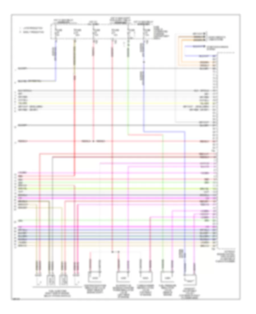
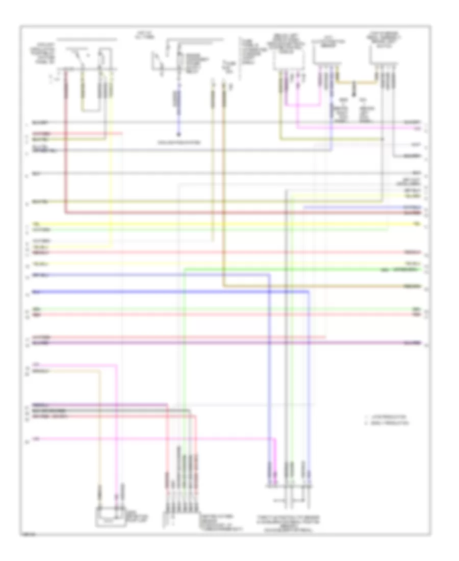
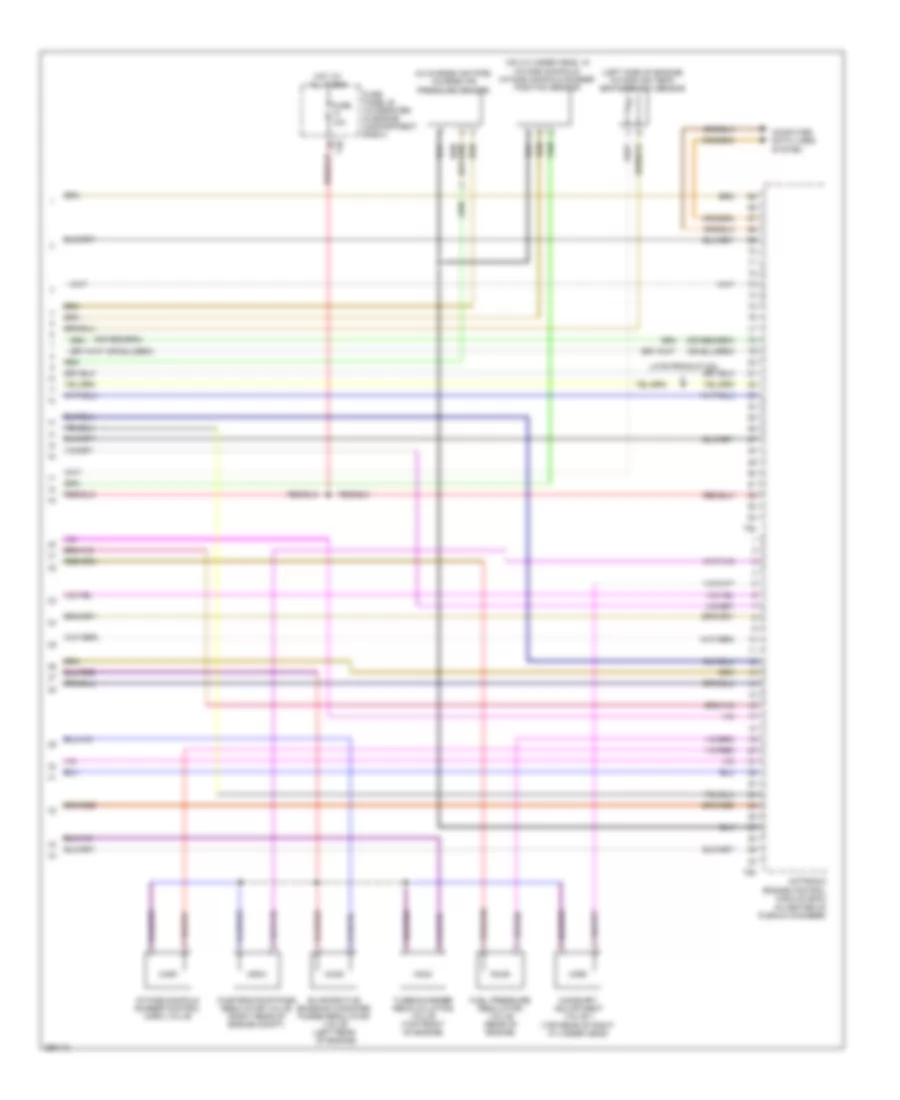
2.0L Turbo, Engine Performance Wiring Diagram, BPY (5 of 5) for Audi A3 2008
 https://portal-diagnostov.com/license.html
Automotive Electricians Portal FZCO
Automotive Electricians Portal FZCO
https://portal-diagnostov.com/license.html
https://portal-diagnostov.com/license.html
Automotive Electricians Portal FZCO
Automotive Electricians Portal FZCOList of elements for 2.0L Turbo, Engine Performance Wiring Diagram, BPY (5 of 5) for Audi A3 2008:
- (in center of plenum chamber)
- 15a
- Camshaft adjustment valve 1 (top rear of right cylinder head)
- Computer data lines system
- Early production
- Evaporative emission canister purge regulator valve (left rear of engine)
- Fuel injectors (right side of engine, below intake manifold)
- Fuel pressure regulator valve (rear of engine)
- Fuse
- Fuse 10a
- Fuse 20a
- Fuse 5a
- Fuse panel b (integrated in engine compartment e-box)
- Hot at all times
- Hot w/ ecm relay energized
- Late production
- Motronic engine control module (ecm)
- Red
- Starting/charging system
- T26
- T40
- T60
- T94
- Turbocharger recirculating valve (top front of engine)
- Wastegate bypass regulator valve (right rear of engine compt)
2.0L Turbo, Engine Performance Wiring Diagram, CBFA (1 of 6) for Audi A3 2008
 https://portal-diagnostov.com/license.html
Automotive Electricians Portal FZCO
Automotive Electricians Portal FZCO
https://portal-diagnostov.com/license.html
https://portal-diagnostov.com/license.html
Automotive Electricians Portal FZCO
Automotive Electricians Portal FZCOList of elements for 2.0L Turbo, Engine Performance Wiring Diagram, CBFA (1 of 6) for Audi A3 2008:
- (in left plenum chamber) g607
- Cooling fans system
- Cruise control system
- Cruise control system starting/ charging system
- Engine coolant temperature (ect) sensor (w/ radiator) (right rear of engine)
- Fuse 10a
- Fuse 15a
- Fuse 20a
- Fuse 5a
- Fuse panel b (integrated in engine compt e-box)
- Hot at all times
- Motronic engine control module (ecm) (in center of plenum chamber)
- Nca
- Oxygen sensor behind three way catalytic convertor (under vehicle, in exhaust)
- Oxygen sensor heater 1 behind three way catalytic convertor (under vehicle, in exhaust)
- Power distribution system
- Radiator identification sensor
- Red
- T40
- T94
2.0L Turbo, Engine Performance Wiring Diagram, CBFA (2 of 6) for Audi A3 2008
 https://portal-diagnostov.com/license.html
Automotive Electricians Portal FZCO
Automotive Electricians Portal FZCO
https://portal-diagnostov.com/license.html
https://portal-diagnostov.com/license.html
Automotive Electricians Portal FZCO
Automotive Electricians Portal FZCOList of elements for 2.0L Turbo, Engine Performance Wiring Diagram, CBFA (2 of 6) for Audi A3 2008:
- (behind left kick panel)
- (behind right kick panel)
- (below left side of dash) vehicle electrical system control module
- (in left plenum chamber) g607
- (left side of engine, below oil filter) after-run coolant pump
- (m/t) clutch position sensor
- (top of brake pedal assembly) brake light switch
- Coolant circulation pump relay (on fuse panel "b")
- Early production
- G44
- G638
- Heated oxygen sensor (in exhaust, at turbocharger exit)
- Late production
- Leak detection pump (ldp)
- Nca
- Red
- Reduced oil pressure switch (late production)
- T11b
- T16a
- Throttle position (tp) sensor & accelerator pedal position sensor 2 (on accelerator pedal)
2.0L Turbo, Engine Performance Wiring Diagram, CBFA (3 of 6) for Audi A3 2008
 https://portal-diagnostov.com/license.html
Automotive Electricians Portal FZCO
Automotive Electricians Portal FZCO
https://portal-diagnostov.com/license.html
https://portal-diagnostov.com/license.html
Automotive Electricians Portal FZCO
Automotive Electricians Portal FZCOList of elements for 2.0L Turbo, Engine Performance Wiring Diagram, CBFA (3 of 6) for Audi A3 2008:
- (behind left kick panel) (early production) g44
- (on right "c" pillar) (late production) g62
- (under right side of rear seat) fuel pump (fp) control module
- Fuel level sensor & transfer fuel pump
- Fuse 40a
- Fuse panel b (integrated in engine compt e-box)
- G15
- G401
- G655 (late production) (on left headlight)
- G673 (early production) (on left front long member)
- Hot at all times
- Ignition coils w/ power output stage (top of cylinder head)
- Late production
- Nca
- Red
- Secondary air injection (air) pump relay
- T40
- To spark plug
2.0L Turbo, Engine Performance Wiring Diagram, CBFA (4 of 6) for Audi A3 2008
 https://portal-diagnostov.com/license.html
Automotive Electricians Portal FZCO
Automotive Electricians Portal FZCO
https://portal-diagnostov.com/license.html
https://portal-diagnostov.com/license.html
Automotive Electricians Portal FZCO
Automotive Electricians Portal FZCOList of elements for 2.0L Turbo, Engine Performance Wiring Diagram, CBFA (4 of 6) for Audi A3 2008:
- (late production) mil ind
- 27a
- Camshaft position (cmp) sensor (front of cylinder head)
- Computer data lines system
- Engine coolant level/temp warning
- Engine coolant temp
- Engine coolant temperature (ect) sensor (right rear of engine)
- Engine electronics ind
- Fuel gauge
- Fuel pressure sensor (on left side of engine, in fuel rail)
- Fuel reserve warning
- Fuse 10a
- Fuse 15a
- Fuse 5a
- Fuse panel c
- Hot at all times
- Instrument cluster control module
- Knock sensor (ks) 1 (on left front of engine block, near head)
- Knock sensor (ks) 2 (on left rear of engine block, near head)
- Nca
- Oil pressure switch
- Oil pressure warning
- Secondary air injection sensor 1
2.0L Turbo, Engine Performance Wiring Diagram, CBFA (5 of 6) for Audi A3 2008
 https://portal-diagnostov.com/license.html
Automotive Electricians Portal FZCO
Automotive Electricians Portal FZCO
https://portal-diagnostov.com/license.html
https://portal-diagnostov.com/license.html
Automotive Electricians Portal FZCO
Automotive Electricians Portal FZCOList of elements for 2.0L Turbo, Engine Performance Wiring Diagram, CBFA (5 of 6) for Audi A3 2008:
- (on engine block near transmission) engine speed (rpm) sensor
- (on intake air duct) mass air flow (maf) sensor
- (on throttle body) throttle valve control module
- Fuel injectors (right side of engine, below intake manifold)
- Fuse 10a
- Fuse panel c
- Hot at all times
- Motronic engine control module (ecm) (in center of plenum chamber)
- Nca
- T60
2.0L Turbo, Engine Performance Wiring Diagram, CBFA (6 of 6) for Audi A3 2008
 https://portal-diagnostov.com/license.html
Automotive Electricians Portal FZCO
Automotive Electricians Portal FZCO
https://portal-diagnostov.com/license.html
https://portal-diagnostov.com/license.html
Automotive Electricians Portal FZCO
Automotive Electricians Portal FZCOList of elements for 2.0L Turbo, Engine Performance Wiring Diagram, CBFA (6 of 6) for Audi A3 2008:
- (in center of plenum chamber)
- (in charge air pipe) charge air pressure sensor
- (left side of engine) intake air temp- erature (iat) sensor
- (on cylinder head, in intake manifold) intake manifold runner position sensor
- (on left headlight) g655
- Camshaft adjustment valve 1 (top rear of right cylinder head)
- Computer data lines system
- Evaporative emission canister purge regulator valve (left rear of engine)
- Fuel pressure regulator valve (rear of engine)
- Fuse 10a
- Fuse panel b (integrated in engine compartment e-box)
- Hot at all times
- Intake manifold runner control (imrc) valve
- Late production
- Motronic engine control module (ecm)
- Nca
- Secondary air injection (air) pump motor
- Secondary air injection (air) solenoid valve
- T40
- T60
- T94
- Turbocharger recalculating valve (top front of engine)
- Wastegate bypass regulator valve (right rear of engine compt)
2.0L Turbo, Engine Performance Wiring Diagram, CCTA (1 of 6) for Audi A3 2008
 https://portal-diagnostov.com/license.html
Automotive Electricians Portal FZCO
Automotive Electricians Portal FZCO
https://portal-diagnostov.com/license.html
https://portal-diagnostov.com/license.html
Automotive Electricians Portal FZCO
Automotive Electricians Portal FZCOList of elements for 2.0L Turbo, Engine Performance Wiring Diagram, CCTA (1 of 6) for Audi A3 2008:
- (in left plenum chamber) g607
- Cooling fans system
- Cruise control system
- Early production
- Engine coolant temperature (ect) sensor (w/ radiator) (right rear of engine)
- Fuse 10a
- Fuse 15a
- Fuse 20a
- Fuse 5a
- Fuse panel b (integrated in engine compt e-box)
- Hot at all times
- Motronic engine control module (ecm) (in center of plenum chamber)
- Nca
- Oxygen sensor behind three way catalytic convertor (under vehicle, in exhaust)
- Red
- Starting/charging system
- T40
- T94
2.0L Turbo, Engine Performance Wiring Diagram, CCTA (2 of 6) for Audi A3 2008
 https://portal-diagnostov.com/license.html
Automotive Electricians Portal FZCO
Automotive Electricians Portal FZCO
https://portal-diagnostov.com/license.html
https://portal-diagnostov.com/license.html
Automotive Electricians Portal FZCO
Automotive Electricians Portal FZCOList of elements for 2.0L Turbo, Engine Performance Wiring Diagram, CCTA (2 of 6) for Audi A3 2008:
- (behind left kick panel)
- (behind right kick panel)
- (below left side of dash) vehicle electrical system control module
- (m/t) clutch position sensor
- (top of brake pedal assembly) brake light switch
- Coolant circulation pump relay (on fuse panel "b")
- Cooling fans system
- Early production
- Engine component power suuply relay
- Fuse 20a
- Fuse panel b (integrated in engine compt e-box)
- G44
- G638
- Heated oxygen sensor (in exhaust, at turbocharger exit)
- Hot at all times
- Late production
- Leak detection pump (ldp)
- Nca
- Red
- T11b
- T16a
- T40
- Throttle position (tp) sensor & accelerator pedal position sensor 2 (on accelerator pedal)
2.0L Turbo, Engine Performance Wiring Diagram, CCTA (3 of 6) for Audi A3 2008
 https://portal-diagnostov.com/license.html
Automotive Electricians Portal FZCO
Automotive Electricians Portal FZCO
https://portal-diagnostov.com/license.html
https://portal-diagnostov.com/license.html
Automotive Electricians Portal FZCO
Automotive Electricians Portal FZCOList of elements for 2.0L Turbo, Engine Performance Wiring Diagram, CCTA (3 of 6) for Audi A3 2008:
- (behind left kick panel) (early production) g44
- (in left plenum chamber) g607
- (left side of engine, below oil filter) after-run coolant pump
- (on right "c" pillar) (late production) g62
- (under right side of rear seat) fuel pump (fp) control module
- Fuel level sensor & transfer fuel pump
- G15
- G401
- G655 (late production) (on left headlight)
- G673 (early production) (on left front long member)
- Ignition coils w/ power output stage (top of cylinder head)
- Late production
- Nca
- Red
- To spark plug
2.0L Turbo, Engine Performance Wiring Diagram, CCTA (4 of 6) for Audi A3 2008
 https://portal-diagnostov.com/license.html
Automotive Electricians Portal FZCO
Automotive Electricians Portal FZCO
https://portal-diagnostov.com/license.html
https://portal-diagnostov.com/license.html
Automotive Electricians Portal FZCO
Automotive Electricians Portal FZCOList of elements for 2.0L Turbo, Engine Performance Wiring Diagram, CCTA (4 of 6) for Audi A3 2008:
- (late production) mil ind
- 27a
- Camshaft position (cmp) sensor (front of cylinder head)
- Computer data lines system
- Engine coolant level/temp warning
- Engine coolant temp
- Engine coolant temperature (ect) sensor (right rear of engine)
- Engine electronics ind
- Fuel gauge
- Fuel pressure sensor (on left side of engine, in fuel rail)
- Fuel reserve warning
- Fuse 10a
- Fuse 15a
- Fuse panel c
- Hot at all times
- Instrument cluster control module
- Knock sensor (ks) 1 (on left front of engine block, near head)
- Nca
- Oil pressure switch
- Oil pressure warning
2.0L Turbo, Engine Performance Wiring Diagram, CCTA (5 of 6) for Audi A3 2008
 https://portal-diagnostov.com/license.html
Automotive Electricians Portal FZCO
Automotive Electricians Portal FZCO
https://portal-diagnostov.com/license.html
https://portal-diagnostov.com/license.html
Automotive Electricians Portal FZCO
Automotive Electricians Portal FZCOList of elements for 2.0L Turbo, Engine Performance Wiring Diagram, CCTA (5 of 6) for Audi A3 2008:
- (on engine block near transmission) engine speed (rpm) sensor
- (on intake air duct) mass air flow (maf) sensor
- (on throttle body) throttle valve control module
- Early production
- Fuel injectors (right side of engine, below intake manifold)
- Fuse 10a
- Fuse panel c
- Hot at all times
- Motronic engine control module (ecm) (in center of plenum chamber)
- T60
2.0L Turbo, Engine Performance Wiring Diagram, CCTA (6 of 6) for Audi A3 2008
 https://portal-diagnostov.com/license.html
Automotive Electricians Portal FZCO
Automotive Electricians Portal FZCO
https://portal-diagnostov.com/license.html
https://portal-diagnostov.com/license.html
Automotive Electricians Portal FZCO
Automotive Electricians Portal FZCOList of elements for 2.0L Turbo, Engine Performance Wiring Diagram, CCTA (6 of 6) for Audi A3 2008:
- (in center of plenum chamber)
- (in charge air pipe) charge air pressure sensor
- (left side of engine) intake air temp- erature (iat) sensor
- (on cylinder head, in intake manifold) intake manifold runner position sensor
- Camshaft adjustment valve 1 (top rear of right cylinder head)
- Computer data lines system
- Evaporative emission canister purge regulator valve (left rear of engine)
- Fuel pressure regulator valve (rear of engine)
- Fuse 10a
- Fuse panel b (integrated in engine compartment e-box)
- Hot at all times
- Intake manifold runner control (imrc) valve
- Late production
- Motronic engine control module (ecm)
- T40
- T60
- T94
- Turbocharger recalculating valve (top front of engine)
- Wastegate bypass regulator valve (right rear of engine compt)
3.2L
3.2L, Engine Performance Wiring Diagram (1 of 5) for Audi A3 2008
 https://portal-diagnostov.com/license.html
Automotive Electricians Portal FZCO
Automotive Electricians Portal FZCO
https://portal-diagnostov.com/license.html
https://portal-diagnostov.com/license.html
Automotive Electricians Portal FZCO
Automotive Electricians Portal FZCOList of elements for 3.2L, Engine Performance Wiring Diagram (1 of 5) for Audi A3 2008:
- Computer data lines system
- Coolant circulation pump relay
- Cruise control system
- Fuse 10a
- Fuse 15a
- Fuse 30a
- Fuse 40a
- Fuse 5a
- Fuse panel b (integrated in engine compt e-box)
- G607 (in left plenum chamber)
- Heated oxygen sensor (in exhaust, at turbocharger exit)
- Heated oxygen sensor 2
- Hot at all times
- Motronic engine control module (in center of plenum chamber)
- Nca
- Oxygen sensor 2 behind three way catalytic convertor
- Oxygen sensor behind three way catalytic convertor (under vehicle, in exhaust)
- Red
- Starting/charging system
- T16a
- T26
- T26 red
- T40
- Throttle position (tp) sensor & accelerator pedal position sensor 2 (on accelerator pedal)
- Vehicle electrical system control module (below left side of dash)
3.2L, Engine Performance Wiring Diagram (2 of 5) for Audi A3 2008
 https://portal-diagnostov.com/license.html
Automotive Electricians Portal FZCO
Automotive Electricians Portal FZCO
https://portal-diagnostov.com/license.html
https://portal-diagnostov.com/license.html
Automotive Electricians Portal FZCO
Automotive Electricians Portal FZCOList of elements for 3.2L, Engine Performance Wiring Diagram (2 of 5) for Audi A3 2008:
- (left side of engine, below oil filter) after-run coolant pump
- (underside of e-box assembly) secondary air injection (air) pump relay
- Brake light switch (top of brake pedal assembly)
- Cooling fans system
- Early production
- Engine coolant temperature (ect) sensor (w/ radiator) (right rear of engine)
- Fuse 10a
- Fuse panel c
- G44 (late production) (behind left kick panel)
- G638 (early production) (behind right kick panel)
- G655 (late production) (on left headlight)
- G655 (on left headlight)
- G673 (early production) (on left front long member)
- Late production
- Leak detection pump (ldp)
- Mass air flow (maf) sensor (on intake air duct)
- Positive crankcase ventilation (pcv) heating element
- Red
- Secondary air injection (air) solenoid valve
- Secondary air injection (air) solenoid valve 2
- Secondary air injection pump motor
- Secondary air injection sensor 1
3.2L, Engine Performance Wiring Diagram (3 of 5) for Audi A3 2008
 https://portal-diagnostov.com/license.html
Automotive Electricians Portal FZCO
Automotive Electricians Portal FZCO
https://portal-diagnostov.com/license.html
https://portal-diagnostov.com/license.html
Automotive Electricians Portal FZCO
Automotive Electricians Portal FZCOList of elements for 3.2L, Engine Performance Wiring Diagram (3 of 5) for Audi A3 2008:
- (below left side of dash) vehicle electrical system control module
- 27a
- Camshaft position sensor (front of cylinder head)
- Camshaft position sensor 2
- Clutch position sensor (m/t)
- Early production
- Engine coolant temperature (ect) sensor (right rear of engine)
- Engine speed (rpm) sensor (on engine block near transmission)
- Fuel pump 2 relay
- Fuse 10a
- Fuse 15a
- Fuse panel c
- G44 (late production) (behind left kick panel)
- G638 (early production) (behind right kick panel)
- Hot at all times
- Knock sensor (ks) 1 (on left front of engine block, near head)
- Knock sensor (ks) 2 (on left rear of engine block, near head)
- Late production
- Nca
- Red
- T11b
- T16a
3.2L, Engine Performance Wiring Diagram (4 of 5) for Audi A3 2008
 https://portal-diagnostov.com/license.html
Automotive Electricians Portal FZCO
Automotive Electricians Portal FZCO
https://portal-diagnostov.com/license.html
https://portal-diagnostov.com/license.html
Automotive Electricians Portal FZCO
Automotive Electricians Portal FZCOList of elements for 3.2L, Engine Performance Wiring Diagram (4 of 5) for Audi A3 2008:
- (behind center console storage compartment) data bus on board diagnostic interface
- (late production) mil ind
- Computer data lines system
- Engine coolant level/temp warning
- Engine coolant temp
- Engine electronics ind
- Fuel gauge
- Fuel level sensor 2
- Fuel reserve warning
- G15
- G401
- G655 (late production) (on left headlight)
- G673 (early production) (on left front long member)
- Ignition coils (coils 1,2,3,4 : top of cylinder haed)
- Instrument cluster control module
- Nca
- Oil pressure switch
- Oil pressure warning
- Red
- Throttle valve control module (on throttle body)
- To spark plugs
3.2L, Engine Performance Wiring Diagram (5 of 5) for Audi A3 2008
 https://portal-diagnostov.com/license.html
Automotive Electricians Portal FZCO
Automotive Electricians Portal FZCO
https://portal-diagnostov.com/license.html
https://portal-diagnostov.com/license.html
Automotive Electricians Portal FZCO
Automotive Electricians Portal FZCOList of elements for 3.2L, Engine Performance Wiring Diagram (5 of 5) for Audi A3 2008:
- (left rear of engine) evaporative emission (evap) canister purge regulator valve
- Below intake manifold)
- Camshaft adjustment valve 1 (exhaust)
- Camshaft adjustment valve 1 (top rear of right cylinder head)
- Cooling fans system
- Early production
- Fuel injectors (right side of engine,
- Fuel level sensor & transfer fuel pump
- Fuel pump relay
- Fuse 10a
- Fuse 6 fuse 7 15a
- Fuse panel b (integrated in engine compt e-box)
- G401
- G44 (early production) (behind left kick panel)
- G62 (late production) (on right "c" pillar)
- Hot at all times
- Intake manifold tuning (imt) valve
- Late production
- Motronic engine control module (in center of plenum chamber)
- Red
- T26
- T40

 Čeština
 Dansk
Dansk Deutsch
 Ελληνικά
 English
 English
 Español
 Suomi
Suomi Français
 Français
 עברית
עברית Hrvatski
 Magyar
 Italiano
 한국어
한국어 Nederlands
 Polski
 Português
 Português
 Română
 Русский
 Slovenčina
 Slovenščina
 Svenska
 Türkçe
 中文 (中国)
