Čeština
 Dansk
Dansk Deutsch
 Ελληνικά
 English
 English
 Español
 Suomi
Suomi Français
 Français
 עברית
עברית Hrvatski
 Magyar
 Italiano
 한국어
한국어 Nederlands
 Polski
 Português
 Português
 Română
 Русский
 Slovenčina
 Slovenščina
 Svenska
 Türkçe
 中文 (中国)

ELECTRONIC SUSPENSION
Electronic Level Control for Cadillac DeVille Concours 1995


List of elements for Electronic Level Control for Cadillac DeVille Concours 1995:
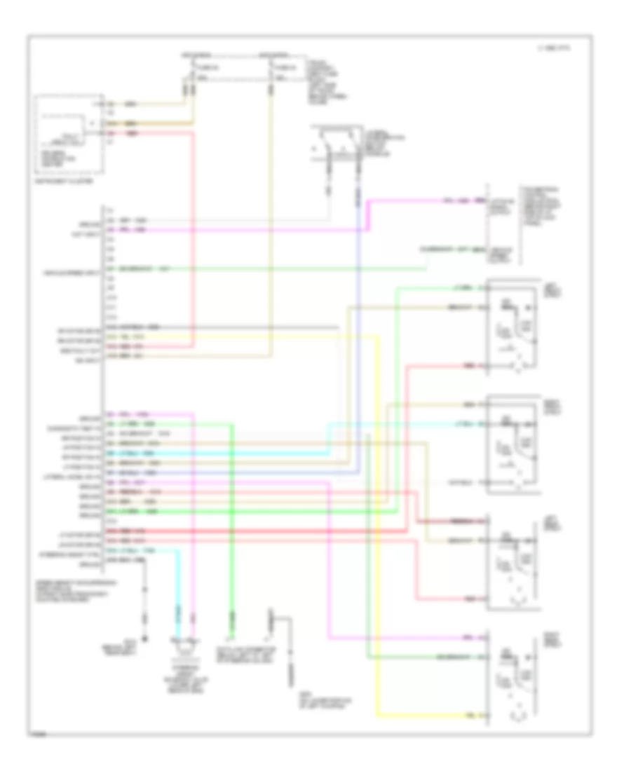
Speed Sensitive Suspension Wiring Diagram for Cadillac DeVille Concours 1995
List of elements for Speed Sensitive Suspension Wiring Diagram for Cadillac DeVille Concours 1995: