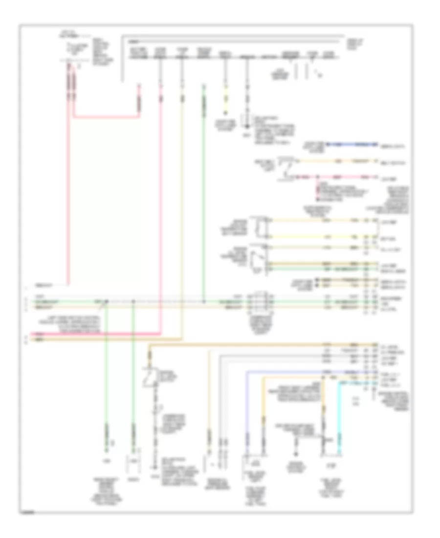
INSTRUMENT CLUSTER
Instrument Cluster Wiring Diagram (1 of 2) for Cadillac XLR V 2006
 https://portal-diagnostov.com/license.html
Automotive Electricians Portal FZCO
Automotive Electricians Portal FZCO
https://portal-diagnostov.com/license.html
https://portal-diagnostov.com/license.html
Automotive Electricians Portal FZCO
Automotive Electricians Portal FZCO
List of elements for Instrument Cluster Wiring Diagram (1 of 2) for Cadillac XLR V 2006:
- A10
- A11
- A12
- A13
- A14
- A15
- A16
- A17
- Abs ind
- Air bag ind
- B10
- B11
- B12
- B13
- B14
- B15
- B16
- B17
- Battery
- Brake fluid
- Brake fluid level switch
- Brake ind
- Class 2 (bcm)
- Class 2 (ecm)
- Class 2 (sdm)
- Computer data lines system
- Coolant temp
- Dic down sw
- Dic ground
- Dic options
- Dic reset
- Dic sw illum
- Dic up sw
- Dim down switch
- Dim up switch
- Dimmer down
- Dimmer select
- Dimmer switch
- Dimmer up
- Dimmer v+
- Dimmer/head up display (hud) switch
- Dome lamp
- Dome switch
- Driver information center (dic) switch
- Driver information center: message center, information display, warning messages
- Engine speed
- Ess
- Exterior lights system
- F10
- Fog lamp ind
- Fuel level
- G101
- G104 (right side of engine compartment, under battery)
- G201
- Gmlan (ebcm)
- Gmlan (ecm)
- Gmlan class 2 (bcm)
- Ground
- Hazard
- Headlamps on ind
- High beam ind
- Ign
- Illum
- Illumination (3 bulbs)
- Image switch
- Information switch
- Instrument panel cluster (ipc)
- Interior lights system
- Ipc
- Km/h ind
- Left turn ind
- Logic
- Malfunction ind
- Message request
- Mph ind
- Oil pressure
- Options switch
- Panel lamps
- Park brake
- Park brake pedal assembly
- Park lamp
- Pnk
- Reset switch
- Right turn ind
- S232
- Seat belt ind
- Security ind
- Serial data
- Speedometer
- Splice pack sp101 (in forward lamp harness, in engine compt, on upper left frame rail, grounded to g101)
- Splice pack sp201 (in instrument panel harness, at base of left a pillar behind trim panel, grounded to g201)
- Tachometer
- Tire pressure ind
- Traction off ind
- Turn signal audible ind
- Underhood fuse block (right rear of engine compartment) c1
- Upshift ind
- Vehicle speed
- Vss
- Washer fluid
- Wiper/washer system
Instrument Cluster Wiring Diagram (2 of 2) for Cadillac XLR V 2006
 https://portal-diagnostov.com/license.html
Automotive Electricians Portal FZCO
Automotive Electricians Portal FZCO
https://portal-diagnostov.com/license.html
https://portal-diagnostov.com/license.html
Automotive Electricians Portal FZCO
Automotive Electricians Portal FZCOList of elements for Instrument Cluster Wiring Diagram (2 of 2) for Cadillac XLR V 2006:
- (driver power seat harness, under seat base)
- (left side ignition control
- +5v ref 1
- 4.4l
- 4.6l
- 5.0 cm from breakout for connector c109)
- Battery positive voltage
- Belt switch
- Body control module (bcm) (behind right side of dash)
- C10
- Cluster fuse 8 15a
- Compt)
- Computer data lines system
- D10
- Ect sig
- Eng oil sens
- Eng speed
- Engine control module (ecm) (behind lower right front fender)
- Engine controls system
- Engine coolant temperature (ect) sensor
- Engine oil level switch
- Engine oil level/ temperature sensor (4.4l)
- Engine oil pressure (eop) sensor
- Fuel level sensor (left)
- Fuel level sensor (right) (top of right fuel tank)
- Fuel lvl 1
- Fuel lvl 2
- Fuel pump & sender assembly (in left fuel tank)
- G102
- G201
- Ground
- Head up display (hud)
- Hot at all times
- Hud message center
- Ignition
- Image down
- Image down signal
- Image up
- Image up signal
- Inflatable restraint sensing & diagnostic module (sdm) (located underneath vehicle console)
- Logic
- Low ref
- Message request
- Mil ctrl
- Module jumper, approximately
- Oil level
- Oil lvl sw
- Oil pres sig
- Pnk
- Radio
- Rear object sensor control module (behind rear compt stowage trim panel)
- S211
- S391 (instrument panel harness, approximately 11.0 cm from yaw rate connector)
- S460 (front body harness, rear defogger capacitor, approximately 20.0 cm from sp302 breakout)
- S462
- Seat belt switch (left)
- Serial data
- Serial data+
- Serial data-
- Splice pack sp102 (in forward lamp harness, in engine compt, on upper right frame rail, grounded to g102)
- Splice pack sp201 (in instrument panel harness, at base of left a pillar behind trim panel, grounded to g201)
- Tan
- Underhood fuse block (right rear of engine c1
- Underhood fuse block (right rear of engine compt)
- Vehicle speed signal
- Vss

 Čeština
 Dansk
Dansk Deutsch
 Ελληνικά
 English
 English
 Español
 Suomi
Suomi Français
 Français
 עברית
עברית Hrvatski
 Magyar
 Italiano
 한국어
한국어 Nederlands
 Polski
 Português
 Português
 Română
 Русский
 Slovenčina
 Slovenščina
 Svenska
 Türkçe
 中文 (中国)
