ANTI-THEFT
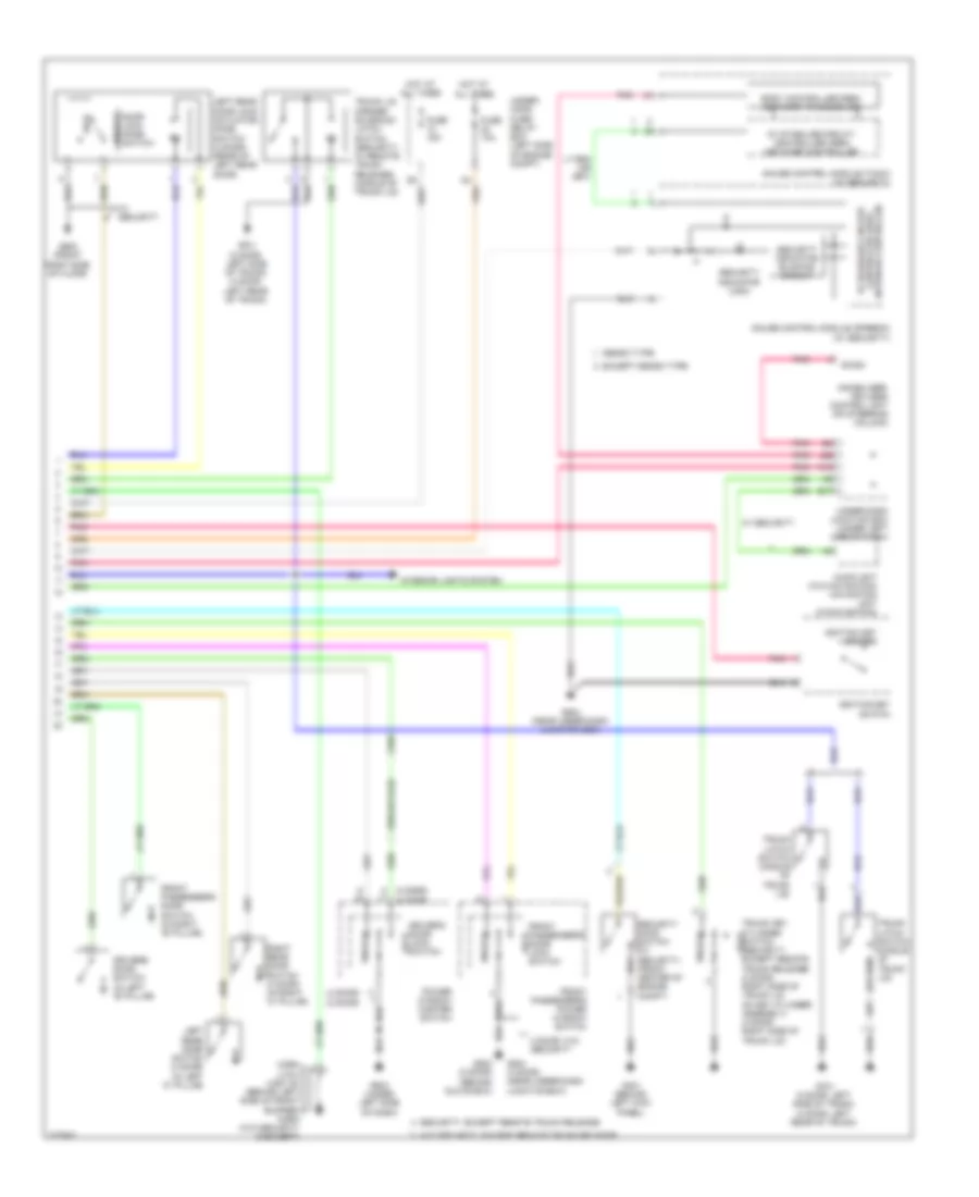
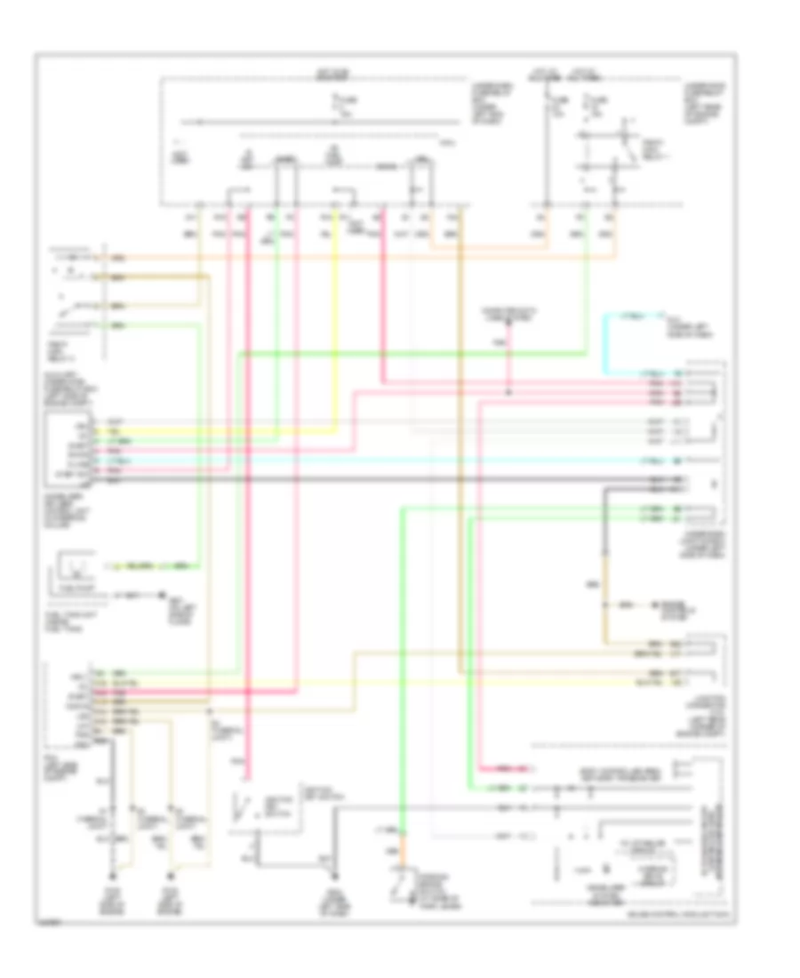
Forced Entry Wiring Diagram, Except Hybrid (1 of 2) for Honda Civic LX 2011
 https://portal-diagnostov.com/license.html
Automotive Electricians Portal FZCO
Automotive Electricians Portal FZCO
https://portal-diagnostov.com/license.html
https://portal-diagnostov.com/license.html
Automotive Electricians Portal FZCO
Automotive Electricians Portal FZCO
List of elements for Forced Entry Wiring Diagram, Except Hybrid (1 of 2) for Honda Civic LX 2011:
- (behind right side of front bumper) (usa: si) high horn
- (not used)
- (on transmission housing) (a/t) transmission range switch
- (usa: w/ security)
- 2-1
- Anti-theft system
- At-p
- B-can
- Door lock knob
- Door lock knob switch
- Door lock relay
- Driver's door lock actuator/knob switch (rear of driver's front door)
- Driver's door unlock relay
- Drswas
- Drswdr
- Drswra
- Drswrd
- E14
- E17
- E19
- E20
- E21
- E31
- E33
- E36
- E37
- Except gx
- Exterior lights system
- F20
- F23
- F27
- F31
- Front passenger's door lock actuator/knob switch (rear of front passenger's front door)
- Fuel fill door switch (gx) (left side of trunk)
- Fuel sw
- Fuse 10a
- Fuse 15a
- Fuse 20a
- Fuse 7.5a
- G101 (si: left rear of engine) (except si: right rear of engine)
- G13
- G16
- G17
- G401 (2 door) (behind left kick panel)
- G401 (behind left kick panel)
- G501 (4 door) (under gauge assembly)
- G501 (under gauge assembly)
- G502 (2 door) (behind glove box)
- G504 (4 door) (near under-dash junction box)
- G601 (front left side of floor)
- G602 (front right side of floor)
- G701 (2 door: left side of trunk) (4 door: left rear of trunk)
- Headlights system
- Hood sw
- Horn relay
- Hot at all times
- Hot in on or start
- Ig key sw
- Ig1
- Junction connector c101 (near brake master cylinder)
- Kc dr lock
- Kc dr unlock
- Key
- Key cylinder switch
- Lock
- Low beam head- light relay
- M10
- Micu
- N13
- P-gnd
- Passenger's door unlock relay
- Pnk
- R16
- Radio sw
- Red
- Rem as lock
- Rem as unlock
- Rem dr lock
- Rem dr unlock
- Right rear door lock actuator/knob switch (4 door) (rear of right rear door)
- S-gnd
- S-gnd2
- S2 (thermal joint)
- Sil as unlock
- Sil dr lock
- Sil dr unlock
- Sil ra unlock
- Sil rd unlock
- T11
- T22
- T23
- T24
- T25
- T26
- T27
- T28
- T29
- T30
- T31
- T32
- T34
- Taillight relay
- Trunk lid opener solenoid relay (security: w/ remote trunk release)
- Trunk sw
- Trunk unlock
- Under-dash fuse/relay box (under left end of dash)
- Unlock
- Usa: w/ security
- Vbu
- W/ security
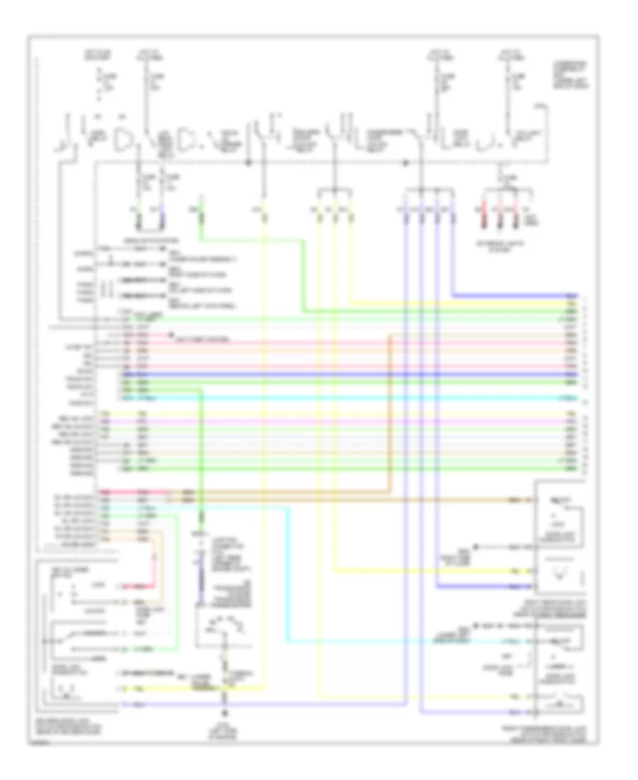
Forced Entry Wiring Diagram, Except Hybrid (2 of 2) for Honda Civic LX 2011
 https://portal-diagnostov.com/license.html
Automotive Electricians Portal FZCO
Automotive Electricians Portal FZCO
https://portal-diagnostov.com/license.html
https://portal-diagnostov.com/license.html
Automotive Electricians Portal FZCO
Automotive Electricians Portal FZCOList of elements for Forced Entry Wiring Diagram, Except Hybrid (2 of 2) for Honda Civic LX 2011:
- (2 door) (4 door)
- (4 door) (2 door)
- 2 door: w/o security
- 5v stabilize circuit/ controller area network controller
- Audio unit (w/o navigation) navigation unit (w/navigation)
- B-can
- Body controller area network transceiver
- Denso type
- Door unlock
- Driver's door lock switch lock
- Driver's door switch (in left "b" pillar)
- E17
- Except denso type
- Front passenger's door lock lock switch
- Front passenger's door switch (in right "b" pillar)
- Front passenger's power window switch
- Fuse 10a
- Fuse 15a
- G401 (behind left kick panel)
- G502 (2 door) (behind glove box)
- G503 (under left side of dash)
- G504 (4 door) (near under-dash junction box)
- G504 (near under-dash junction box)
- G602 (front right side of floor)
- G701 (2 door: left side of trunk) (4 door: left rear of trunk)
- Gauge control module (speedo) (w/ security)
- Gauge control module (tach) (w/ security)
- Horn (low) (usa: si) (behind left side of front bumper) horn (w/o security & except)
- Hot at all times
- Ignition key switch
- Immobilizer- keyless control unit (on steering column)
- Interior lights system
- J22
- K13
- Left rear door lock actuator/ knob switch (4 door) (rear of left rear door)
- Left rear door switch (4 door) (in left "c" pillar)
- Lock
- Lock knob switch
- Pnk
- Power window master switch
- Right rear door switch (4 door) (in right "c" pillar)
- Security hood switch (w/ security) (front center of engine compt)
- Security indicator (usa)
- Security indicator blinking circuit
- Security: except remote trunk release
- Trunk key cylinder switch (security: lock except remote trunk release) (2 door: right side of trunk lid, on key cylinder assembly) (4 door: right side of trunk lid)
- Trunk latch switch (middle of trunk lid)
- Trunk lid opener solenoid/ latch switch (security: w/ remote trunk release) (middle of trunk lid)
- Under- hood fuse/ relay box (left side of engine compt)
- Under-dash junction box (under left side of dash)
- Unlock
- W/ security
- W/o security: except remote trunk release
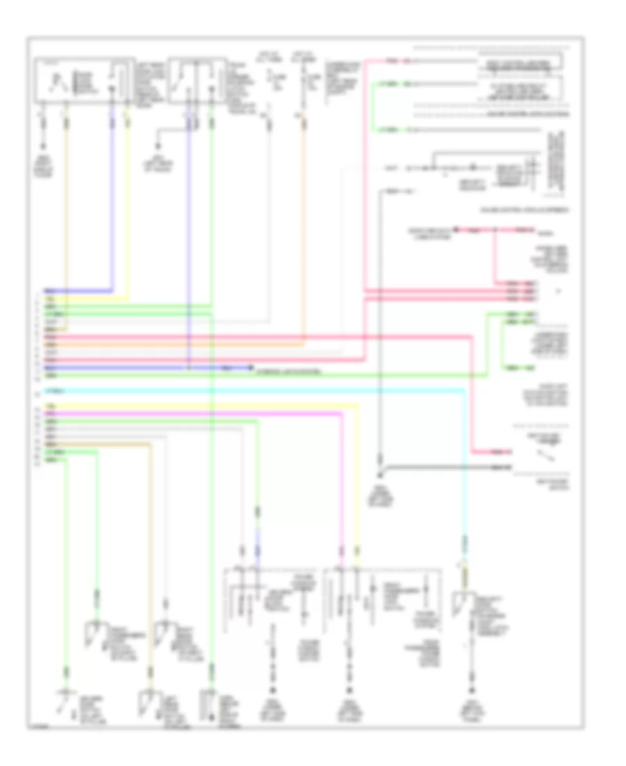
Forced Entry Wiring Diagram, Hybrid (1 of 2) for Honda Civic LX 2011
 https://portal-diagnostov.com/license.html
Automotive Electricians Portal FZCO
Automotive Electricians Portal FZCO
https://portal-diagnostov.com/license.html
https://portal-diagnostov.com/license.html
Automotive Electricians Portal FZCO
Automotive Electricians Portal FZCOList of elements for Forced Entry Wiring Diagram, Hybrid (1 of 2) for Honda Civic LX 2011:
- (not used)
- (on transmission housing) transmission range switch
- (thermal joint) s2
- (under gauge assembly)
- Anti-theft system
- At-p
- B-can
- Door lock knob
- Door lock knob switch
- Door lock relay
- Driver's door lock actuator/knob switch (rear of driver's door)
- Driver's door unlock relay
- Drswas
- Drswdr
- Drswra
- Drswrd
- E14
- E17
- E19
- E20
- E21
- E31
- E33
- E36
- E37
- Exterior lights
- F20
- F23
- F27
- Front passenger's door lock actuator/knob switch (rear of right front door)
- Fuse 10a
- Fuse 15a
- Fuse 20a
- Fuse 7.5a
- G102 (left side of engine)
- G13
- G16
- G17
- G401 (behind left kick panel)
- G501
- G501 (under gauge assembly)
- G504 (under left side of dash)
- G601 (on left side of floor)
- G602 (right side of floor)
- Headlights system
- Hood sw
- Horn relay
- Hot at all times
- Hot in on or start
- Ig key sw
- Ig1
- Junction connector c101 (left rear corner of engine compt)
- Kc dr lock
- Kc dr unlock
- Key
- Key cylinder switch
- Lock
- Low beam head- light relay
- M10
- Micu
- N13
- P-gnd
- Passenger's door unlock relay
- Pnk
- R16
- Radio sw
- Red
- Rem as lock
- Rem as unlock
- Rem dr lock
- Rem dr unlock
- Right rear door lock actuator/knob switch (rear of right rear door)
- S-gnd
- S-gnd2
- Sil as unlock
- Sil dr lock
- Sil dr unlock
- Sil ra unlock
- Sil rd unlock
- System
- T22
- T23
- T24
- T25
- T26
- T27
- T28
- T29
- T30
- T31
- T32
- T34
- Taillight relay
- Trunk lid opener relay
- Trunk sw
- Under-dash fuse/relay box (under left end of dash)
- Unlock
- Vbu
Forced Entry Wiring Diagram, Hybrid (2 of 2) for Honda Civic LX 2011
 https://portal-diagnostov.com/license.html
Automotive Electricians Portal FZCO
Automotive Electricians Portal FZCO
https://portal-diagnostov.com/license.html
https://portal-diagnostov.com/license.html
Automotive Electricians Portal FZCO
Automotive Electricians Portal FZCOList of elements for Forced Entry Wiring Diagram, Hybrid (2 of 2) for Honda Civic LX 2011:
- 5v stabilize circuit/ controller area network controller
- Audio unit (w/o navigation) navigation unit (w/ navigation)
- B-can
- Body controller area network transceiver
- Computer data lines system
- Door unlock
- Driver's door lock switch lock
- Driver's door switch (on left "b" pillar)
- E17
- Front passenger's door lock switch
- Front passenger's door switch (on right "b" pillar)
- Front passenger's power window switch
- Fuse 10a
- Fuse 15a
- G401 (behind left kick panel)
- G503 (under left side of dash)
- G504 (under left side of dash)
- G602 (right side of floor)
- G701 (left rear of trunk)
- Gauge control module (speedo)
- Gauge control module (tach)
- Horn (behind left side of front bumper)
- Hot at all times
- Ignition key switch
- Immobilizer- keyless control unit (in steering column)
- Interior lights system
- J22
- K13
- Left rear door lock actuator/ knob switch (rear of left rear door)
- Left rear door switch (on left "c" pillar)
- Lock
- Lock knob switch
- Pnk
- Power window master switch
- Power windows system
- Right rear door switch (on right "c" pillar)
- Security hood switch (on engine compt hood latch assembly)
- Security indicator
- Security indicator blinking circuit
- Trunk lid opener solenoid/ latch switch (usa) (middle of trunk lid)
- Under-dash junction box (under left side of dash)
- Under-hood fuse/relay box (left rear of engine compt)
- Unlock
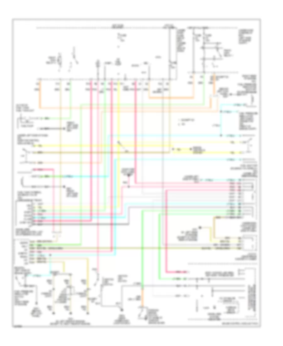
Immobilizer Wiring Diagram, Except Hybrid for Honda Civic LX 2011
 https://portal-diagnostov.com/license.html
Automotive Electricians Portal FZCO
Automotive Electricians Portal FZCO
https://portal-diagnostov.com/license.html
https://portal-diagnostov.com/license.html
Automotive Electricians Portal FZCO
Automotive Electricians Portal FZCOList of elements for Immobilizer Wiring Diagram, Except Hybrid for Honda Civic LX 2011:
- (behind left kick panel) g401
- (front left side of floor) g601
- (gx)
- (in top of fuel tank) fuel tank unit
- (not used)
- (or pnk)
- (right rear of engine)
- (under left side of dash) (gx) injector control module relay
- (under left side of dash) dlc
- 10v stabilize circuit
- A15
- A22
- A41
- A44
- B-can
- B17
- Body controller area network transceiver
- C36
- C40
- C44 lg2
- Computer data lines system
- Controller area 5v stabilize circuit/
- D6 (except si) (si)
- Ecm/pcm (left side of engine compt)
- Engine controls system
- Except gx
- F10
- F24
- Fuel pressure regulator leak check connector (gx) (front of engine compt)
- Fuel pressure regulator shut-off solenoid valve
- Fuel pressure regulator switch (gx) (right rear of engine)
- Fuel pump
- Fuel shut-off solenoid valve relay (gx) (under left side of dash)
- Fuel tank internal solenoid valve (gx) (left side of trunk)
- Fuse 10a
- Fuse 15a
- G101 (si: left rear of engine) (except si: right rear of engine)
- G11
- G401 (behind left kick panel)
- G504 (near under-dash junction box)
- G601 (front left side of floor)
- Gauge control module (tach)
- Hot at all times
- Hot in on or start
- Ig key sw
- Ig1
- Ig1 fuel pump
- Ignition key switch
- Immobilizer system indicator
- Immobilizer- keyless control unit (on steering column)
- Imofpr
- J/c c101 (near brake master cylinder)
- J11
- J21
- J22
- K-line
- K13
- Lg1
- Micu
- Mrly
- Network controller
- Parking brake switch (at base of parking brake lever)
- Pf2sw
- Pgm-fi main relay 1
- Pgm-fi main relay 2
- Pnk
- R11
- R12
- R16
- S-net
- S-net5v
- S3 (thermal joint)
- Under- dash fuse/ relay box (under left end of dash)
- Under-dash junction box (under left side of dash)
- Under-hood fuse/relay box (left side of engine compt)
- Vbu
- Warning drive circuit
Immobilizer Wiring Diagram, Hybrid for Honda Civic LX 2011
 https://portal-diagnostov.com/license.html
Automotive Electricians Portal FZCO
Automotive Electricians Portal FZCO
https://portal-diagnostov.com/license.html
https://portal-diagnostov.com/license.html
Automotive Electricians Portal FZCO
Automotive Electricians Portal FZCOList of elements for Immobilizer Wiring Diagram, Hybrid for Honda Civic LX 2011:
- (not used)
- 10v stabilize circuit
- A15
- A17
- A22
- A44
- Auxiliary under-hood fuse/relay box (left side of engine compt)
- B-can
- B17
- B22
- B36
- Body controller area network transceiver
- C36
- C40
- C44
- Computer data
- Controller area 5v stabilize circuit/
- Dlc (under left side of dash)
- Engine controls system
- F24
- Fuel pump
- Fuel tank unit (inside fuel tank)
- Fuse 10a
- Fuse 15a
- G102 (left side of engine)
- G11
- G504 (under left side of dash)
- G601 (on left side of floor)
- Gauge control module (tach)
- Hot at all times
- Hot in on or start
- Ig key sw
- Ig1
- Ig1 fuel pump
- Ignition key switch
- Immobilizer system indicator
- Immobilizer- keyless control unit (in steering column)
- Imoflr
- J11
- J21
- J22
- Junction connector c101 (left rear corner of engine compt)
- K-line
- K13
- Lg1
- Lg2
- Lines system
- Micu
- Mrly
- Network controller
- Parking brake switch (at base of park lever)
- Pcm (left side of engine compt)
- Pg1
- Pg2
- Pgm-fi main relay 1
- Pgm-fi main relay 2
- Pnk
- R11 (not used)
- R12
- R16
- S-net
- S1 (thermal joint)
- S2 (thermal joint)
- S3 (thermal joint)
- S4 (thermal joint)
- Under-dash fuse/relay box (under left end of dash)
- Under-dash junction box (under left side of dash)
- Under-hood fuse/relay box (left rear of engine compt)
- Vbu
- Warning drive circuit

 Čeština
 Dansk
Dansk Deutsch
 Ελληνικά
 English
 English
 Español
 Suomi
Suomi Français
 Français
 עברית
עברית Hrvatski
 Magyar
 Italiano
 한국어
한국어 Nederlands
 Polski
 Português
 Português
 Română
 Русский
 Slovenčina
 Slovenščina
 Svenska
 Türkçe
 中文 (中国)
