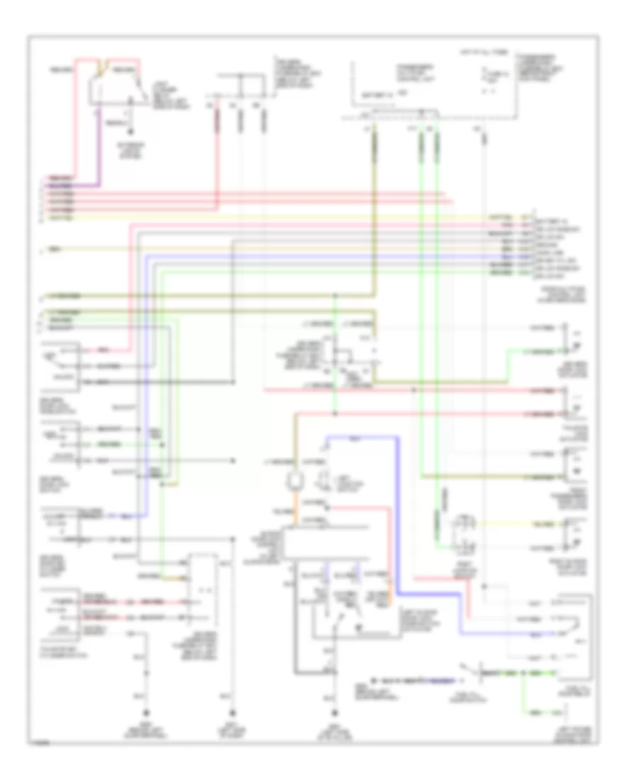
ANTI-THEFT
Immobilizer Wiring Diagram for Honda Odyssey LX 2004
 https://portal-diagnostov.com/license.html
Automotive Electricians Portal FZCO
Automotive Electricians Portal FZCO
https://portal-diagnostov.com/license.html
https://portal-diagnostov.com/license.html
Automotive Electricians Portal FZCO
Automotive Electricians Portal FZCO
List of elements for Immobilizer Wiring Diagram for Honda Odyssey LX 2004:
- A15
- A17
- B19
- B20
- Driver's under-dash fuse/relay box (below left end of dash)
- E12
- Fuel pump
- Fuel pump ctrl
- Fuel tank unit
- Fuse 15a
- Fuse 15a
- Fuse 7.5a
- G101 (at left side of engine compt)
- G551 (at left "b" pillar)
- Gauge assembly
- Ground
- H16
- Hot at all times
- Hot in on or start
- Hot in start
- Immob code in
- Immob enable
- Immob lt ctrl
- Immobilizer receiver unit (on steering column, near steering lock)
- Immobilizer system indicator
- Junction connector c104 (at left side of engine compartment)
- Junction connector c105 (at left side of engine compt)
- Passenger's under-dash fuse/relay box (behind right kick panel)
- Pcm (behind lower center of dash)
- Pgm-fi main relay (behind left side of dash)
- Pnk
- Pwr input
- Q10
- Red
- Starter cut relay
- Under-hood fuse/ relay box (at right side of engine compt)
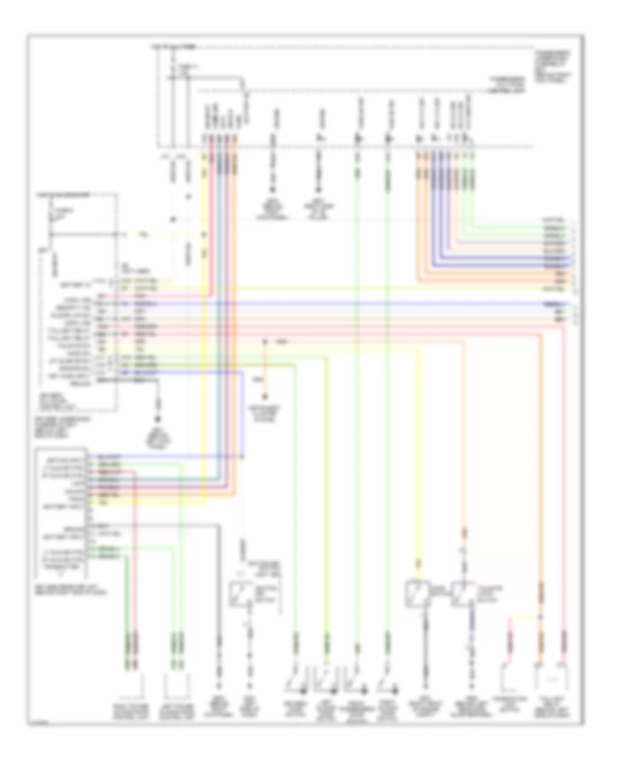
Power Door Locks Wiring Diagram, Except LX (1 of 3) for Honda Odyssey LX 2004
 https://portal-diagnostov.com/license.html
Automotive Electricians Portal FZCO
Automotive Electricians Portal FZCO
https://portal-diagnostov.com/license.html
https://portal-diagnostov.com/license.html
Automotive Electricians Portal FZCO
Automotive Electricians Portal FZCOList of elements for Power Door Locks Wiring Diagram, Except LX (1 of 3) for Honda Odyssey LX 2004:
- 10a
- 7.5a
- A10
- A12
- A13
- A14
- A15
- A16
- A17
- A18
- A20
- A22
- A24
- B11
- B16
- B22
- Battery in
- Battery input
- Combination light switch
- Comm line
- Dr door sw
- Dr lck sw
- Driver's door switch
- Driver's multiplex control unit
- Driver's under-dash fuse/relay box (below left end of dash)
- Front passenger's door switch
- Fuse 13
- Fuse 9
- G14
- G201 (right front of engine compt)
- G401 (left side of dash)
- G501 (behind left kick panel)
- G503 (behind right kick panel)
- G552 (behind left rear side quarterpanel)
- G581 (right side of "b" pillar)
- G9 (not used)
- Ground
- Hood sw
- Hood switch
- Hot at all times
- Hot in on or start
- Ign input
- Ignition input
- Ignition key switch
- Ignition key switch/ light key
- Instrument cluster system
- J11
- J12
- Key cyl sw
- Key in ign input
- Keyless receiver unit (behind right end of dash)
- Lck knob sw
- Left power sliding door control unit
- Left sliding door switch
- Lft slide dr sw
- Lock
- Lt slid dr ctrl
- O19
- Panic
- Pass dr sw
- Passenger's multiplex control unit
- Passenger's under-dash fuse/relay box (behind right kick panel)
- Pnk
- Right power sliding door control unit
- Right sliding door switch
- Rt slid dr ctrl
- Security ind
- Slid dr lck sw
- Slid dr sw
- Tailgate latch switch
- Tailgate sw
- Taillight relay
- Taillight relay (behind left side of dash)
- Transmitter
- Unlock
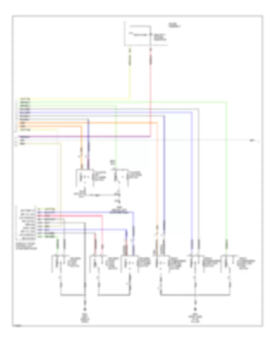
Power Door Locks Wiring Diagram, Except LX (2 of 3) for Honda Odyssey LX 2004
 https://portal-diagnostov.com/license.html
Automotive Electricians Portal FZCO
Automotive Electricians Portal FZCO
https://portal-diagnostov.com/license.html
https://portal-diagnostov.com/license.html
Automotive Electricians Portal FZCO
Automotive Electricians Portal FZCOList of elements for Power Door Locks Wiring Diagram, Except LX (2 of 3) for Honda Odyssey LX 2004:
- A12
- A15
- A16
- A17
- A18
- B21
- Battery in
- Comm line
- Door multiplex control unit (in driver's door)
- Dr lck sw
- Driver's door key cylinder switch
- Driver's door lock knob switch
- Driver's door lock switch
- Front passenger's door key cylinder switch
- Front passenger's door lock knob switch
- Front passenger's door lock switch
- G401 (left side of dash)
- G552 (behind left quarterpanel)
- G581 (right side of "b" pillar)
- Gauge assembly
- Ground
- Indicators
- Key cyl sw
- Lck knob sw
- Lock
- Pnk
- Security system indicator
- Tailgate key cylinder switch
- Tailgate lock knob switch
- Unlock
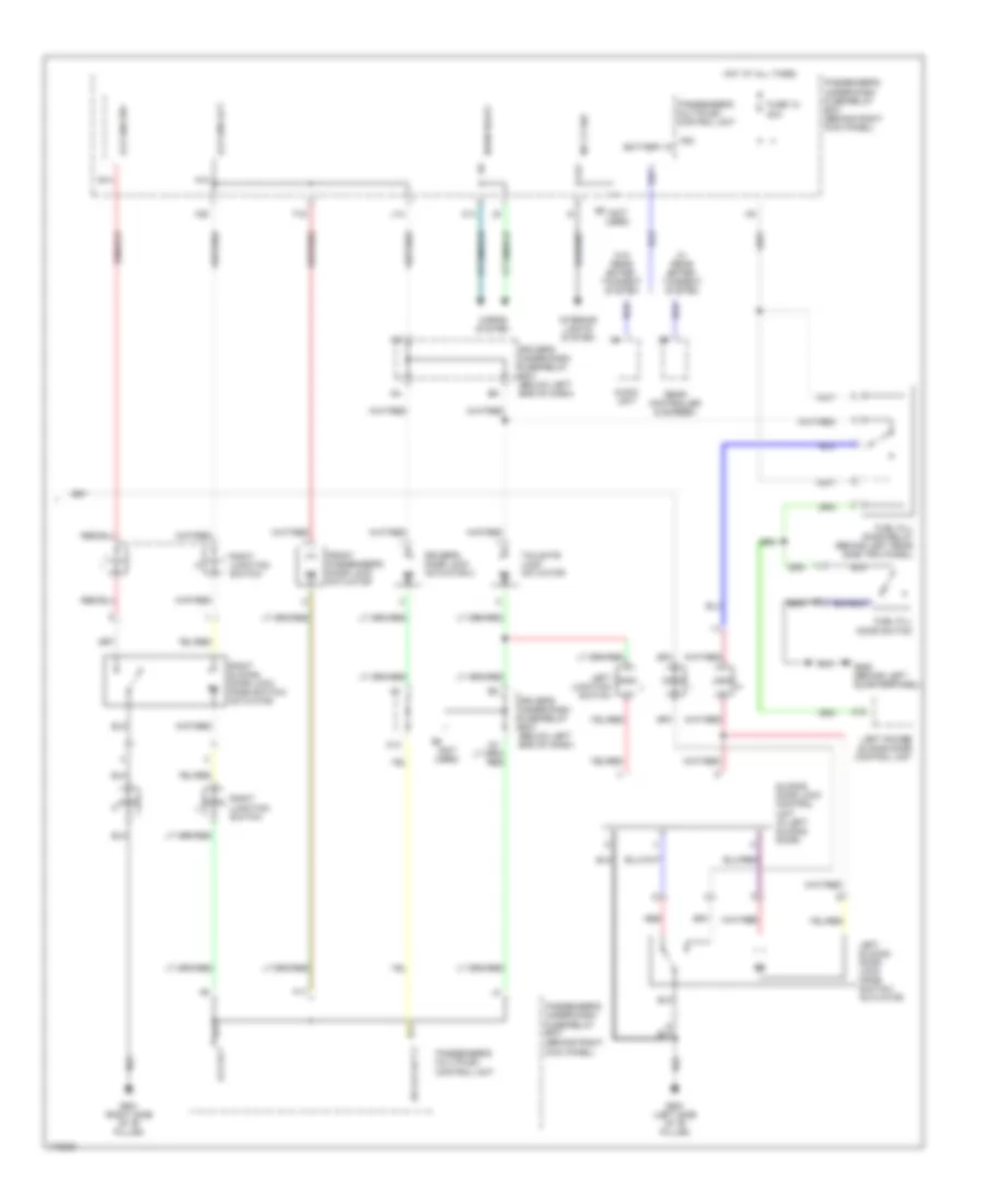
Power Door Locks Wiring Diagram, Except LX (3 of 3) for Honda Odyssey LX 2004
 https://portal-diagnostov.com/license.html
Automotive Electricians Portal FZCO
Automotive Electricians Portal FZCO
https://portal-diagnostov.com/license.html
https://portal-diagnostov.com/license.html
Automotive Electricians Portal FZCO
Automotive Electricians Portal FZCOList of elements for Power Door Locks Wiring Diagram, Except LX (3 of 3) for Honda Odyssey LX 2004:
- (not used)
- 20a
- A10
- A11 lck act
- A18
- A20
- A21
- A23
- Audio unit
- B11 dr lck act 2
- B14
- B21
- Battery in
- C14
- Driver's door lock actuator 2
- Driver's under-dash fuse/relay box (below left end of dash)
- F15
- F17
- Front passenger's door lock actuator
- Fuel fill door relay (behind left rear side trim panel)
- Fuel fill door switch
- Fuse 12
- G551 (left side of "b" pillar)
- G552 (behind left quarterpanel)
- G581 (right side of "b" pillar)
- Horn relay
- Horns system
- Hot at all times
- Int lt sw
- Interior lights system
- J14
- K13
- Kick panel)
- Lck knb act
- Lck knb sw
- Left junction switch
- Left power sliding door control unit
- Left sliding door lock knob switch/ actuator
- Passenger's multiplex control unit
- Passenger's under-dash fuse/relay box (behind right
- Passenger's under-dash fuse/relay box (behind right kick panel)
- Rear controller & screen
- Red
- Right junction switch
- Right sliding door lock knob switch/ actuator
- Sliding door lock control unit (in left sliding door)
- Tailgate lock actuator
- W/ rear enter- tainment system
- W/o rear enter- tainment system
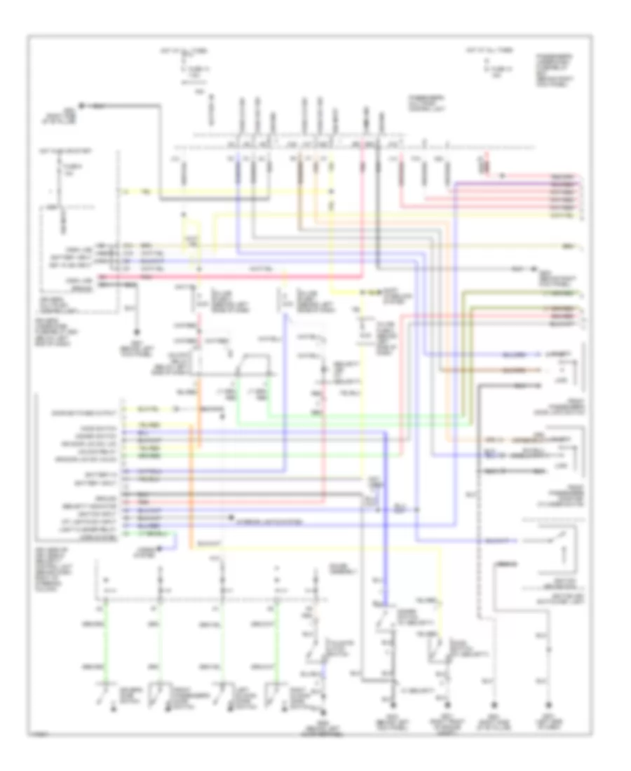
Power Door Locks Wiring Diagram, LX with Keyless Entry (1 of 2) for Honda Odyssey LX 2004
 https://portal-diagnostov.com/license.html
Automotive Electricians Portal FZCO
Automotive Electricians Portal FZCO
https://portal-diagnostov.com/license.html
https://portal-diagnostov.com/license.html
Automotive Electricians Portal FZCO
Automotive Electricians Portal FZCOList of elements for Power Door Locks Wiring Diagram, LX with Keyless Entry (1 of 2) for Honda Odyssey LX 2004:
- (not used)
- 10a
- 15a
- 7.5a
- A10
- A12
- A13
- A16
- A17
- A20
- A22
- A24
- B11
- B22
- Battery in
- Battery input
- Comm line
- Disarm switch
- Disarm switch (w/ security)
- Door switches output
- Dr door lck sw lck
- Dr door lck sw unlck
- Driver's door switch
- Driver's multiplex control unit
- Driver's under-dash fuse/relay box (below left end of dash)
- F15
- Front passenger's door key cylinder switch
- Front passenger's door lock switch
- Front passenger's door switch
- Fuse 10
- Fuse 13
- Fuse 9
- G14
- G201 (right front of engine compt)
- G303 (behind left kick panel)
- G401 (left side of dash)
- G501 (behind left kick panel)
- G503 (behind right kick panel)
- G552 (behind left quarterpanel)
- G581 (right side of "b" pillar)
- Gauge assembly
- Ground
- Hood switch
- Hood switch (w/ security)
- Horn system
- Horns system
- Hot at all times
- Hot in on or start
- Ign input
- Ignition input
- Ignition key switch
- Ignition key switch/key light
- In-line fuse 1 (behind left side of dash)
- In-line fuse 2 (behind left side of dash)
- In-line fuse 3 (behind left side of dash)
- Int lights sw input
- Interior lights system
- J12
- J14
- Key in ign input
- Keyless or keyless & security control unit (behind dash, right of steering column)
- Left sliding door switch
- Light flasher relay
- Lock
- O19
- Pass key sw
- Pass lck sw
- Passenger's multiplex control unit
- Passenger's under-dash fuse/relay box (behind right kick panel)
- Pnk
- Red
- Right sliding door switch
- Security indicator
- Security led (w/
- Security)
- Shift interlock system
- Tailgate latch switch
- Unlock
- Unlock relay
- Unlock relay (below left side of dash)
- W/ security
Power Door Locks Wiring Diagram, LX with Keyless Entry (2 of 2) for Honda Odyssey LX 2004
 https://portal-diagnostov.com/license.html
Automotive Electricians Portal FZCO
Automotive Electricians Portal FZCO
https://portal-diagnostov.com/license.html
https://portal-diagnostov.com/license.html
Automotive Electricians Portal FZCO
Automotive Electricians Portal FZCOList of elements for Power Door Locks Wiring Diagram, LX with Keyless Entry (2 of 2) for Honda Odyssey LX 2004:
- (below left end of dash)
- 20a
- A11
- A12
- A15
- A16
- A17
- A18
- A23
- Battery in
- Comm line
- Door multiplex control unit (in driver's door)
- Dr key cyl sw
- Dr lck knob sw
- Dr lck sw
- Driver's door key cylinder switch
- Driver's door lock actuator
- Driver's door lock knob switch
- Driver's door lock switch
- Driver's under-dash fuse/relay box
- Driver's under-dash fuse/relay box (below left end of dash)
- Exterior lights system
- F17
- Front passenger's door lock actuator
- Fuel fill door relay
- Fuel fill door switch
- Fuse 12
- G401 (left side of dash)
- G551 (left side of "b" pillar)
- G552 (behind left quarterpanel)
- G6 (not used)
- Ground
- Hot at all times
- I18
- K13
- Left junction switch
- Left power sliding door control unit
- Left sliding door lock knob switch/ actuator
- Light flasher relay (below left side of dash)
- Lock
- Passenger's multiplex control unit
- Passenger's under-dash fuse/relay box (behind right kick panel)
- Pnk
- Right junction switch
- Right sliding door lock actuator
- Sliding door lock control unit (in left sliding door)
- Tailgate key cylinder switch
- Tailgate lock actuator
- Unlock

 Čeština
 Dansk
Dansk Deutsch
 Ελληνικά
 English
 English
 Español
 Suomi
Suomi Français
 Français
 עברית
עברית Hrvatski
 Magyar
 Italiano
 한국어
한국어 Nederlands
 Polski
 Português
 Português
 Română
 Русский
 Slovenčina
 Slovenščina
 Svenska
 Türkçe
 中文 (中国)
