ENGINE PERFORMANCE
4.2L
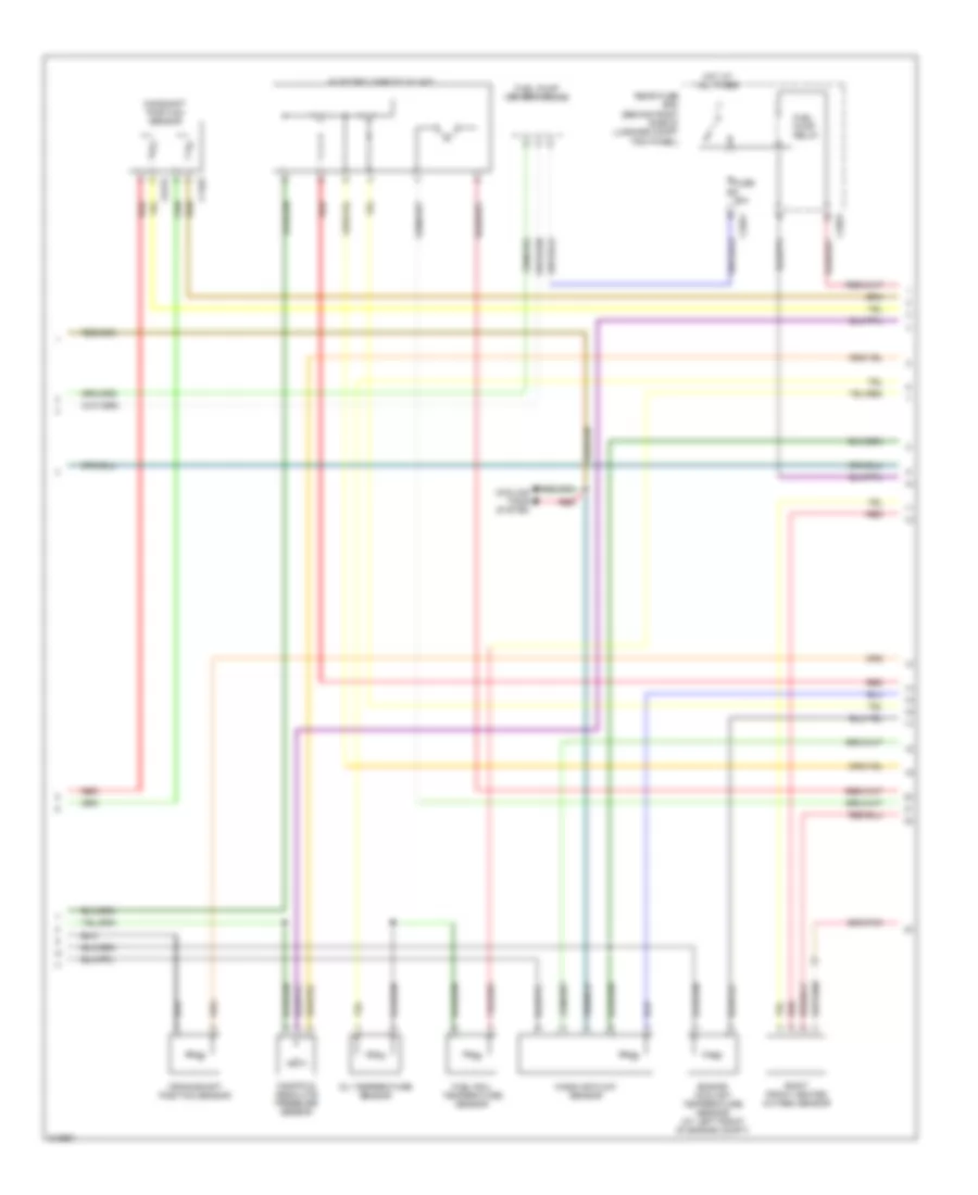
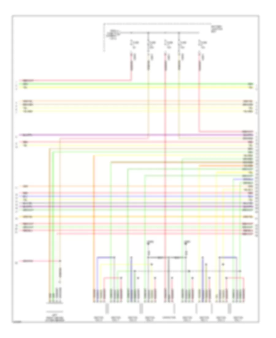
4.2L, Engine Performance Wiring Diagram (1 of 4) for Land Rover Range Rover Supercharged 2006
 https://portal-diagnostov.com/license.html
Automotive Electricians Portal FZCO
Automotive Electricians Portal FZCO
https://portal-diagnostov.com/license.html
https://portal-diagnostov.com/license.html
Automotive Electricians Portal FZCO
Automotive Electricians Portal FZCO
List of elements for 4.2L, Engine Performance Wiring Diagram (1 of 4) for Land Rover Range Rover Supercharged 2006:
- (hot climates) condenser fan
- 5v ref 1
- 5v ref 2
- Acc
- Accelerator pedal position sensor
- Alt_monitor
- Batt
- Battery junction box
- Brake boost pump
- Brake boost pump relay
- Brake sw (a/l)
- C0028
- C0559
- C0560
- C0570
- C0571
- C0572
- C0587
- C0634
- C0635
- C0810
- C1856
- Cam a gnd
- Cam b gnd
- Can h in
- Can h out
- Can l in
- Can l out
- Central junction box
- Computer data lines system
- Crank
- Crank -
- Demand 1
- Demand 2
- Dmtl heater
- Dmtl pump
- Dmtl valve
- Ecm power
- Engine control module (ecm) (inside "e" box)
- Engine control module relay
- Exterior lights system computer data lines system
- F/pump control
- F/pump monitor
- Fan pwm
- Fuse 10a
- Fuse 15a
- Fuse 20a
- Fuse 5a
- Gnd 1
- Gnd 2
- Hego a gnd
- Hego a htr
- Hego a sig
- Hego b gnd
- Hego b htr
- Hego b sig
- Hot at all times
- Hot in on or start
- Ign
- Ignition switch
- Leak detection pump
- Left rear heated oxygen sensor
- Lock
- Maf gnd
- Main relay
- P/n
- Power gnd1
- Power gnd2
- Power gnd3
- Red
- Right rear heated oxygen sensor
- Sen gnd 3
- Sen gnd 4
- Sensor gnd5
- Signal gnd
- Srs signal
- Start
- Start relay-
- Starting/ charging system
- Throttle power
- To fuse (diagram 3 of 4)
- Transfer box control module (at left rear of engine compt)
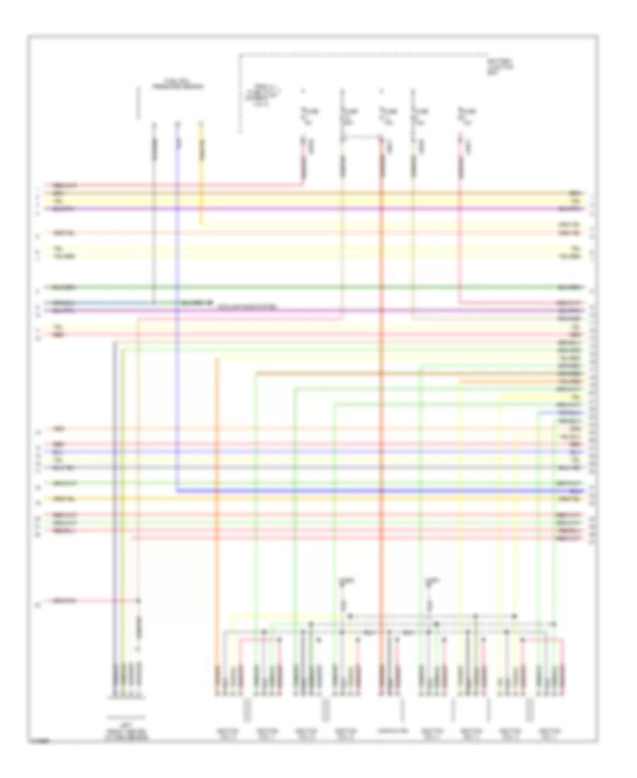
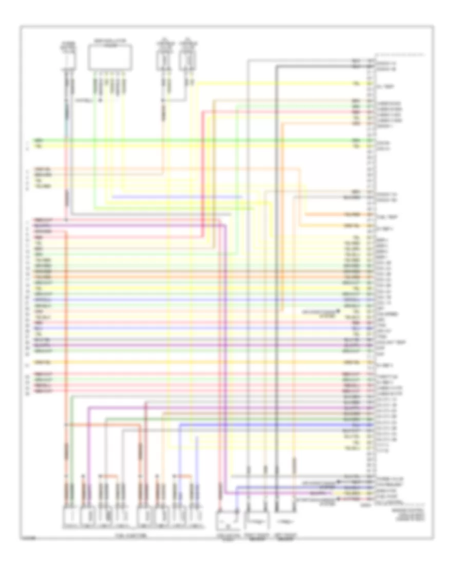
4.2L, Engine Performance Wiring Diagram (2 of 4) for Land Rover Range Rover Supercharged 2006
 https://portal-diagnostov.com/license.html
Automotive Electricians Portal FZCO
Automotive Electricians Portal FZCO
https://portal-diagnostov.com/license.html
https://portal-diagnostov.com/license.html
Automotive Electricians Portal FZCO
Automotive Electricians Portal FZCOList of elements for 4.2L, Engine Performance Wiring Diagram (2 of 4) for Land Rover Range Rover Supercharged 2006:
- C0176
- C1463
- C2021
- C2022
- Camshaft position sensor
- Cooling fans system
- Crankshaft position sensor
- Electric throttle unit
- Engine coolant temperature sensor (at left front of engine compt)
- Fuel pump driver module
- Fuel pump relay
- Fuel rail temperature sensor
- Fuse 25a
- Hot at all times
- Manifold absolute pressure sensor
- Mass air flow sensor
- Oil temperature sensor
- Rear fuse box (behind right side of luggage compt trim panel)
- Red
- Right front heated oxygen sensor
4.2L, Engine Performance Wiring Diagram (3 of 4) for Land Rover Range Rover Supercharged 2006
 https://portal-diagnostov.com/license.html
Automotive Electricians Portal FZCO
Automotive Electricians Portal FZCO
https://portal-diagnostov.com/license.html
https://portal-diagnostov.com/license.html
Automotive Electricians Portal FZCO
Automotive Electricians Portal FZCOList of elements for 4.2L, Engine Performance Wiring Diagram (3 of 4) for Land Rover Range Rover Supercharged 2006:
- Battery junction box
- C0562
- C0570
- C0571
- C2651
- Capacitor
- Cooling fans system
- From fuse 19 a (diagram 1 of 4)
- Fuel rail pressure sensor
- Fuse 10a
- Fuse 15a
- Fuse 20a
- Fuse 5a
- Ignition coil 1
- Ignition coil 2
- Ignition coil 3
- Ignition coil 4
- Ignition coil 5
- Ignition coil 6
- Ignition coil 7
- Ignition coil 8
- Left front heated oxygen sensor
- Red
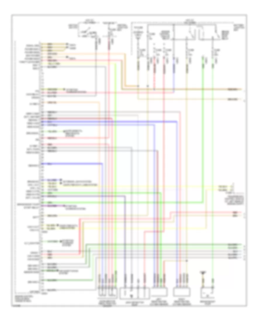
4.2L, Engine Performance Wiring Diagram (4 of 4) for Land Rover Range Rover Supercharged 2006
 https://portal-diagnostov.com/license.html
Automotive Electricians Portal FZCO
Automotive Electricians Portal FZCO
https://portal-diagnostov.com/license.html
https://portal-diagnostov.com/license.html
Automotive Electricians Portal FZCO
Automotive Electricians Portal FZCOList of elements for 4.2L, Engine Performance Wiring Diagram (4 of 4) for Land Rover Range Rover Supercharged 2006:
- 5v ref 3
- 5v ref 4
- 5v ref 5
- 5v ref 6
- Afm iat
- Air conditioning system
- Alt_control
- C0634
- Cam a+
- Cam b+
- Coil 1a
- Coil 1b
- Coil 2a
- Coil 2b
- Coil 3a
- Coil 3b
- Coil 4a
- Coil 4b
- Coolant temp
- Cooling fan e box
- Crank +
- E-box fan
- Engine control module (ecm) (inside "e" box)
- Fan request
- Fan speed
- Fuel injectors
- Fuel press
- Fuel pump
- Fuel temp
- Igf1
- Igf2
- Inj cyl 1a
- Inj cyl 1b
- Inj cyl 2a
- Inj cyl 2b
- Inj cyl 3a
- Inj cyl 3b
- Inj cyl 4a
- Inj cyl 4b
- Intercooler temp
- Knock 1a+
- Knock 1a-
- Knock 1b+
- Knock 1b-
- Left knock sensor
- Maf
- Map
- Map/boost press
- Nca
- Oil temp
- Purge control valve
- Purge valve
- Red
- Right knock sensor
- Starting/charging system
- Temperature & manifold absolute pressure sensor
- Throttle+
- Throttle-
- Tps1
- Tps2
- Uhego a gnd
- Uhego a htr
- Uhego a sig
- Uhego b gnd
- Uhego b htr
- Uhego b sig
4.4L
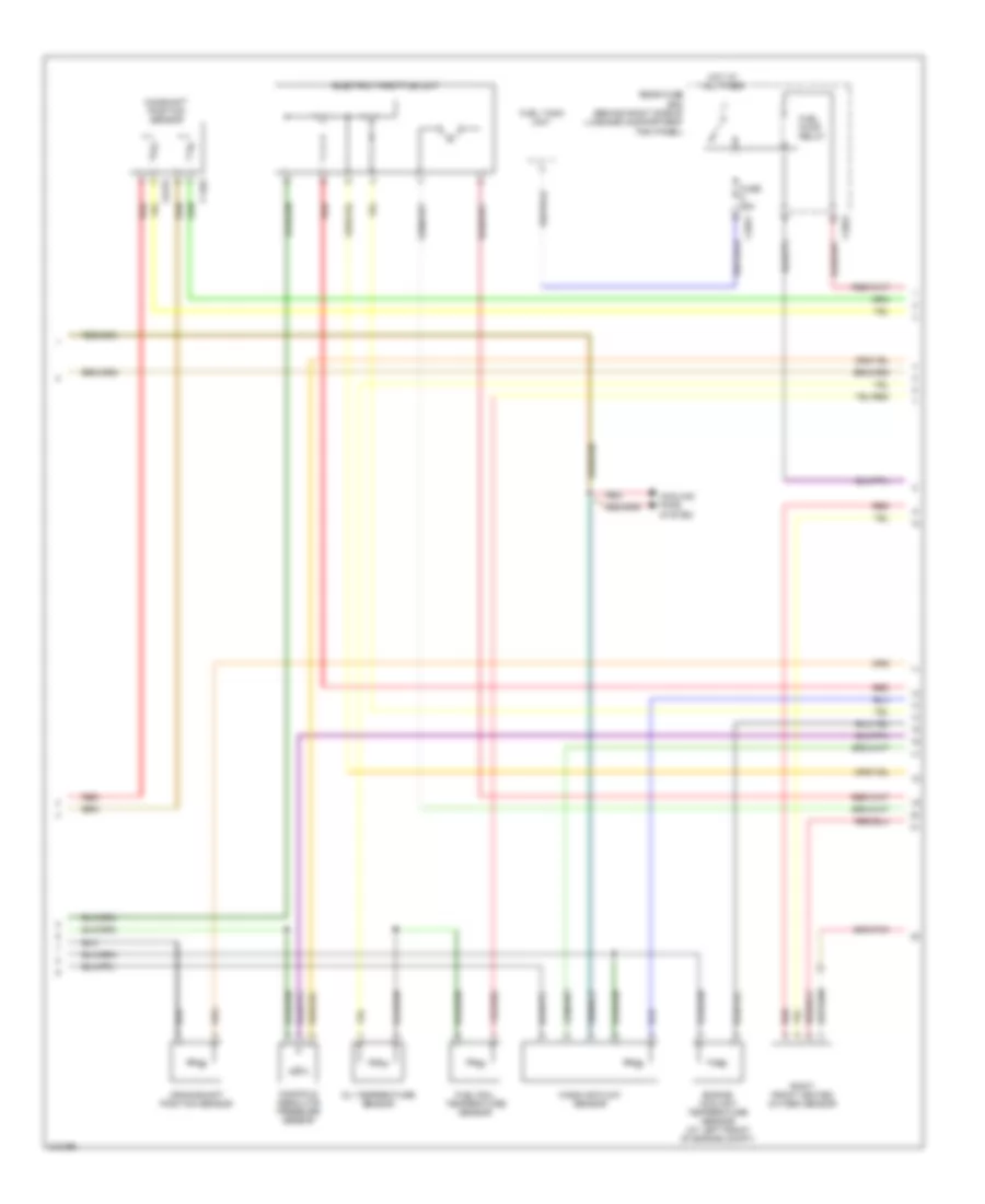
4.4L, Engine Performance Wiring Diagram (1 of 4) for Land Rover Range Rover Supercharged 2006
 https://portal-diagnostov.com/license.html
Automotive Electricians Portal FZCO
Automotive Electricians Portal FZCO
https://portal-diagnostov.com/license.html
https://portal-diagnostov.com/license.html
Automotive Electricians Portal FZCO
Automotive Electricians Portal FZCOList of elements for 4.4L, Engine Performance Wiring Diagram (1 of 4) for Land Rover Range Rover Supercharged 2006:
- 5v ref 1
- 5v ref 2
- Acc
- Accelerator pedal position sensor
- Air conditioning system
- Alt_monitor
- Batt
- Battery junction box
- Brake boost pump
- Brake boost pump relay
- Brake sw
- C0028
- C0559
- C0560
- C0570
- C0571
- C0572
- C0587
- C0634
- C0635
- C0810
- C1856
- Cam a gnd
- Cam b gnd
- Can h in
- Can h out
- Can l in
- Can l out
- Central junction box
- Computer data lines system
- Crank
- Crank -
- Demand 1
- Demand 2
- Dmtl heater
- Dmtl pump
- Dmtl valve
- Ecm power
- Engine control module (ecm) (inside "e" box)
- Engine control module relay
- Exterior lights system
- Fuse 10a
- Fuse 15a
- Fuse 20a
- Fuse 5a
- Gnd 1
- Gnd 2
- Hego a gnd
- Hego a htr
- Hego a sig
- Hego b gnd
- Hego b htr
- Hego b sig
- Hot at all times
- Hot in on
- Ign
- Ignition switch
- Leak detection pump
- Left rear heated oxygen sensor
- Lock
- Maf gnd
- Main relay
- P/n
- Power gnd1
- Power gnd2
- Power gnd3
- Red
- Right rear heated oxygen sensor
- Sen gnd 3
- Sen gnd 4
- Sensor gnd5
- Signal gnd
- Srs signal
- Start
- Start relay
- Starting/ charging system
- Throttle power
- To fuse (diagram 3 of 4)
- Transfer box control module (at left rear of engine compt)
4.4L, Engine Performance Wiring Diagram (2 of 4) for Land Rover Range Rover Supercharged 2006
 https://portal-diagnostov.com/license.html
Automotive Electricians Portal FZCO
Automotive Electricians Portal FZCO
https://portal-diagnostov.com/license.html
https://portal-diagnostov.com/license.html
Automotive Electricians Portal FZCO
Automotive Electricians Portal FZCOList of elements for 4.4L, Engine Performance Wiring Diagram (2 of 4) for Land Rover Range Rover Supercharged 2006:
- electric throttle unit
- C0176
- C1463
- C2021
- C2022
- Camshaft position sensor
- Cooling fans system
- Crankshaft position sensor
- Engine coolant temperature sensor (at left front of engine compt)
- Fuel pump relay
- Fuel rail temperature sensor
- Fuel tank unit
- Fuse 25a
- Hot at all times
- Manifold absolute pressure sensor
- Mass air flow sensor
- Oil temperature sensor
- Rear fuse box (behind right side of luggage compartment trim panel)
- Red
- Right front heated oxygen sensor
4.4L, Engine Performance Wiring Diagram (3 of 4) for Land Rover Range Rover Supercharged 2006
 https://portal-diagnostov.com/license.html
Automotive Electricians Portal FZCO
Automotive Electricians Portal FZCO
https://portal-diagnostov.com/license.html
https://portal-diagnostov.com/license.html
Automotive Electricians Portal FZCO
Automotive Electricians Portal FZCOList of elements for 4.4L, Engine Performance Wiring Diagram (3 of 4) for Land Rover Range Rover Supercharged 2006:
- Battery junction box
- C0562
- C0570
- C0571
- C2651
- Capacitor
- From fuse 19 a (diagram 1 of 4)
- Fuse 10a
- Fuse 15a
- Fuse 20a
- Fuse 5a
- Ignition coil 1
- Ignition coil 2
- Ignition coil 3
- Ignition coil 4
- Ignition coil 5
- Ignition coil 6
- Ignition coil 7
- Ignition coil 8
- Left front heated oxygen sensor
- Red
4.4L, Engine Performance Wiring Diagram (4 of 4) for Land Rover Range Rover Supercharged 2006
 https://portal-diagnostov.com/license.html
Automotive Electricians Portal FZCO
Automotive Electricians Portal FZCO
https://portal-diagnostov.com/license.html
https://portal-diagnostov.com/license.html
Automotive Electricians Portal FZCO
Automotive Electricians Portal FZCOList of elements for 4.4L, Engine Performance Wiring Diagram (4 of 4) for Land Rover Range Rover Supercharged 2006:
- 5v ref 3
- 5v ref 4
- Afm iat
- Air conditioning system
- Alt_control
- C0634
- Cam a+
- Cam b+
- Coil 1a
- Coil 1b
- Coil 2a
- Coil 2b
- Coil 3a
- Coil 3b
- Coil 4a
- Coil 4b
- Coolant temp
- Cooling fan e box
- Crank +
- E-box fan
- Egr 1
- Egr 2
- Egr 3
- Egr 4
- Egr modulator valve
- Engine control module (ecm) (inside "e" box)
- Fan request
- Fan speed
- Fuel injectors
- Fuel pump
- Fuel temp
- Igf1
- Igf2
- Inj cyl 1a
- Inj cyl 1b
- Inj cyl 2a
- Inj cyl 2b
- Inj cyl 3a
- Inj cyl 3b
- Inj cyl 4a
- Inj cyl 4b
- Knock 1a+
- Knock 1a-
- Knock 1b+
- Knock 1b-
- Left knock sensor
- Maf
- Map
- Nca
- Oil temp
- Oil variable valve timing 1
- Oil variable valve timing 2
- Purge control valve
- Purge valve
- Red
- Right knock sensor
- Starting/charging system
- Throttle-
- Tps1
- Tps2
- Uhego a gnd
- Uhego a htr
- Uhego a sig
- Uhego b gnd
- Uhego b htr
- Uhego b sig
- Vvt a
- Vvt b

 Čeština
 Dansk
Dansk Deutsch
 Ελληνικά
 English
 English
 Español
 Suomi
Suomi Français
 Français
 עברית
עברית Hrvatski
 Magyar
 Italiano
 한국어
한국어 Nederlands
 Polski
 Português
 Português
 Română
 Русский
 Slovenčina
 Slovenščina
 Svenska
 Türkçe
 中文 (中国)
