
 Čeština
 Dansk
Dansk Deutsch
 Ελληνικά
 English
 English
 Español
 Suomi
Suomi Français
 Français
 עברית
עברית Hrvatski
 Magyar
 Italiano
 한국어
한국어 Nederlands
 Polski
 Português
 Português
 Română
 Русский
 Slovenčina
 Slovenščina
 Svenska
 Türkçe
 中文 (中国)

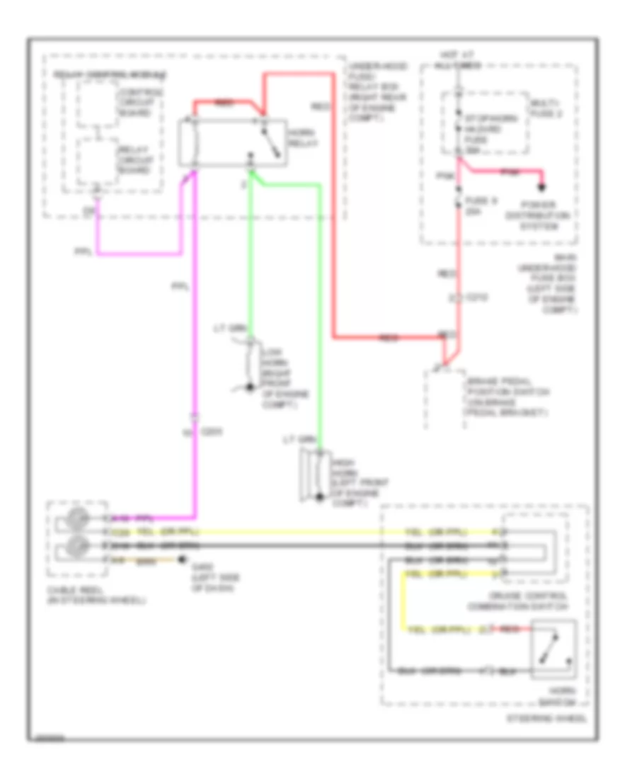
HORN
Horn Wiring Diagram for Honda Odyssey Touring 2013
List of elements for Horn Wiring Diagram for Honda Odyssey Touring 2013:

TRANSMISSIONTRUNK, TAILGATE, FUEL DOORWARNING SYSTEMSWIPER/WASHERANTI-LOCK BRAKESBODY CONTROL MODULESANTI-THEFTAIR CONDITIONINGCOOLING FANCOMPUTER DATA LINESDEFOGGERSENGINE PERFORMANCEEXTERIOR LIGHTSCRUISE CONTROLHEADLIGHTSHORNGROUND DISTRIBUTIONINTERIOR LIGHTSPOWER DISTRIBUTIONMEMORY SYSTEMSNAVIGATIONPOWER DOOR LOCKSINSTRUMENT CLUSTERPOWER MIRRORSPOWER SEATSSTARTING/CHARGINGRADIOPOWER TOP/SUNROOFSUPPLEMENTAL RESTRAINTSSHIFT INTERLOCKPOWER WINDOWS