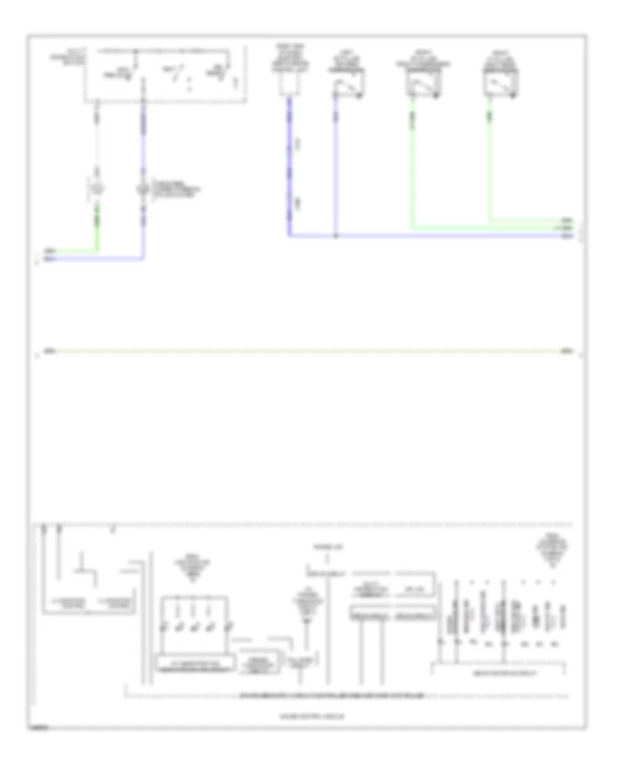
INSTRUMENT CLUSTER
Instrument Cluster Wiring Diagram, Electric Vehicle (1 of 3) for Honda Fit EV 2014
 https://portal-diagnostov.com/license.html
Automotive Electricians Portal FZCO
Automotive Electricians Portal FZCO
https://portal-diagnostov.com/license.html
https://portal-diagnostov.com/license.html
Automotive Electricians Portal FZCO
Automotive Electricians Portal FZCO
List of elements for Instrument Cluster Wiring Diagram, Electric Vehicle (1 of 3) for Honda Fit EV 2014:
- (left center of dash) j/c c008
- 10v stabilizing circuit
- 26v dc/dc converter
- 5v control circuit
- 5v regulator
- Air conditioning system
- Amp
- Anti-lock brakes system
- B-can h
- B-can l
- B-can transceiver
- Computer data lines system
- Cruise control ind
- Cruise control system
- Cruise main ind
- Dimming circuit
- Drive circuit indicator
- Engine controls system
- Exterior lights system
- F-can h
- F-can l
- F-can transceiver
- From illumination encoder (diagram 3 of 3)
- Fuse 7.5a
- G201 (left side of dash)
- Gauge control module
- Hot at all times
- Hot in on or start
- Illumination control & dimming circuit for ambient (green/red)
- Illumination control & dimming circuit for ambient (white)
- Illumination control & dimming circuit for dial illumination (white)
- Illumination control & dimming circuit for dial plate (white)
- Illumination control & dimming circuit for mid back light (amber)
- Illumination control & dimming circuit for mid back light (white)
- Illumination control & dimming circuit for mode color (red/green/white)
- Illumination control & dimming circuit for pointer (white)
- Illumination control & dimming circuit for range lcd back light (white/green)
- Illumination control & dimming circuit for sp lcd back light (white)
- Interior lights system
- J/c c006 (left center of dash)
- Km/h & mph change switch
- Kw1 ind
- Kw10 ind
- Kw2 ind
- Kw3 ind
- Kw4 ind
- Kw5 ind
- Kw6 ind
- Kw7 ind
- Kw8 ind
- Kw9 ind
- Lights-on ind
- Micu
- Mixing circuit
- Parking brake switch (base of parking brake lever)
- Pnk
- Red
- Speaker
- To a/t gear position indicator driving circuit (diagram 2 of 3)
- To charging system ind (diagram 3 of 3)
- To illumination encoder (diagram 3 of 3)
- To immobilizer ind (diagram 3 of 3)
- To pin 21 (diagram 3 of 3)
- Under-dash fuse/relay box (under left end of dash)
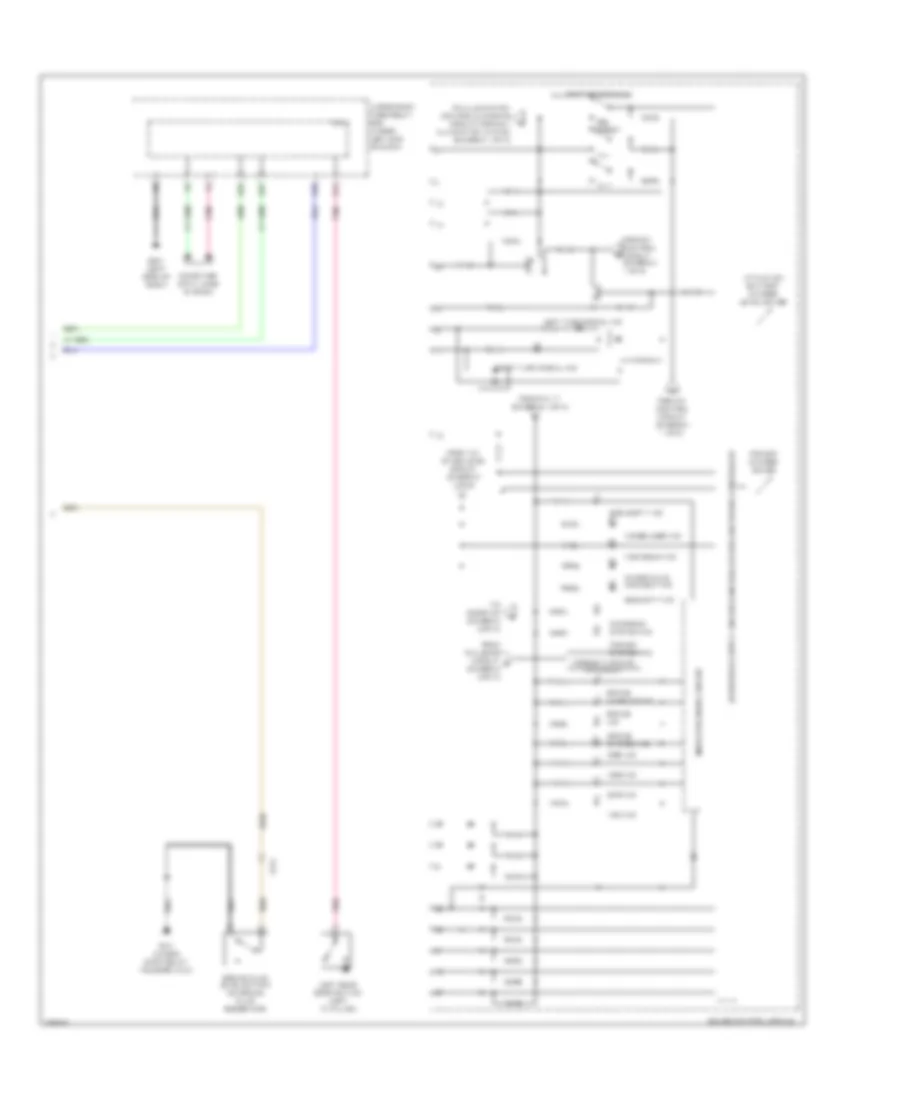
Instrument Cluster Wiring Diagram, Electric Vehicle (2 of 3) for Honda Fit EV 2014
 https://portal-diagnostov.com/license.html
Automotive Electricians Portal FZCO
Automotive Electricians Portal FZCO
https://portal-diagnostov.com/license.html
https://portal-diagnostov.com/license.html
Automotive Electricians Portal FZCO
Automotive Electricians Portal FZCOList of elements for Instrument Cluster Wiring Diagram, Electric Vehicle (2 of 3) for Honda Fit EV 2014:
- (left "b" pillar) driver's door switch
- (right "b" pillar) front passenger's door switch
- (right "c" pillar) right rear door switch
- (right end of dash) electric servo brake control unit
- A/t gear position indicator driving circuit
- C305
- C314
- Cable reel (under steering column cover)
- Cut-off ind side air bag
- Door ind
- Drive circuit
- Fail-safe circuit
- Forced turning-off circuit
- From charging system ind (diagram 3 of 3)
- From lights-on ind (diagram 1 of 3)
- Gauge control module
- Illumination control
- Indicator drive circuit
- Low charge ind
- Message ind
- Multi- information display
- Multi- information switch
- Next
- Range lcd
- Reduced ind power
- Reminder ind seat belt
- Sel reset
- Sp lcd
- To forced turning-on circuit 3 of 3)
- Tpms ind
- Vsa off ind
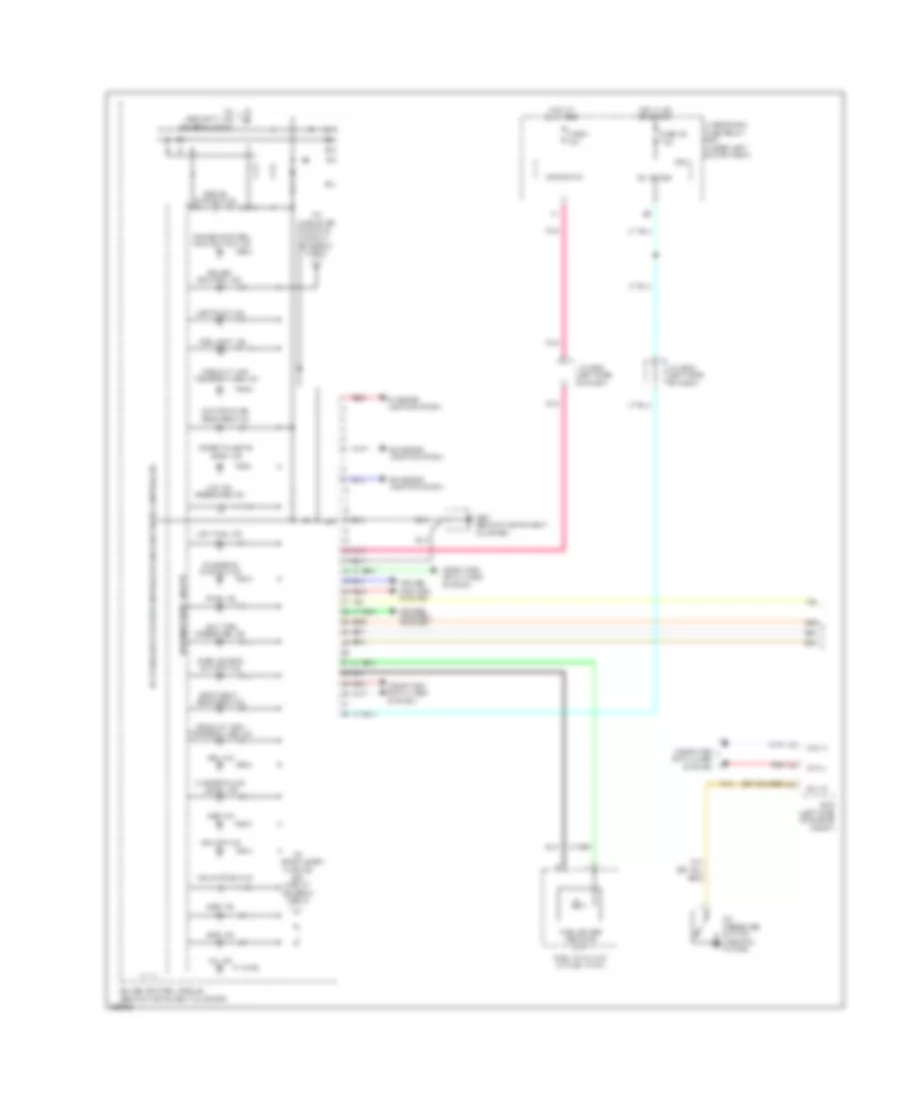
Instrument Cluster Wiring Diagram, Electric Vehicle (3 of 3) for Honda Fit EV 2014
 https://portal-diagnostov.com/license.html
Automotive Electricians Portal FZCO
Automotive Electricians Portal FZCO
https://portal-diagnostov.com/license.html
https://portal-diagnostov.com/license.html
Automotive Electricians Portal FZCO
Automotive Electricians Portal FZCOList of elements for Instrument Cluster Wiring Diagram, Electric Vehicle (3 of 3) for Honda Fit EV 2014:
- Abs ind
- Brake fluid level switch (on brake fluid reservoir)
- Brake ind
- Brake system ind
- Brake warning ind
- C314
- Charg plug connect ind
- Charging system ind
- Computer data lines system
- D13
- D22
- D26
- D27
- Eps ind
- Forced turning- on circuit
- From 10v stabilizing circuit (diagram 1 of 3)
- From 5v control circuit (diagram 1 of 3)
- From fail-safe circuit g (diagram 2 of 3)
- From pin 17 (diagram 1 of 3)
- G101 (under- dash relay holders 2 & 3)
- G201 (left side of dash)
- Gauge control module
- High beam ind
- Ill +
- Ill -
- Illumination encoder
- Immobilizer ind
- Indicator drive circuit
- Left rear door switch (left "c" pillar)
- Left turn signal ind
- Lithium ion battery charge level gauge
- Micu
- Pnk
- Power system ind
- Power/ charge gauge
- Right turn signal ind
- Security ind
- Sel reset
- Soc empty ind
- Srs ind
- To door ind (diagram 2 of 3)
- To illumination control & dimming circuit for dial illuminaton (white) (diagram 1 of 3)
- Under-dash fuse/relay box (under left end of dash)
- Vsa ind
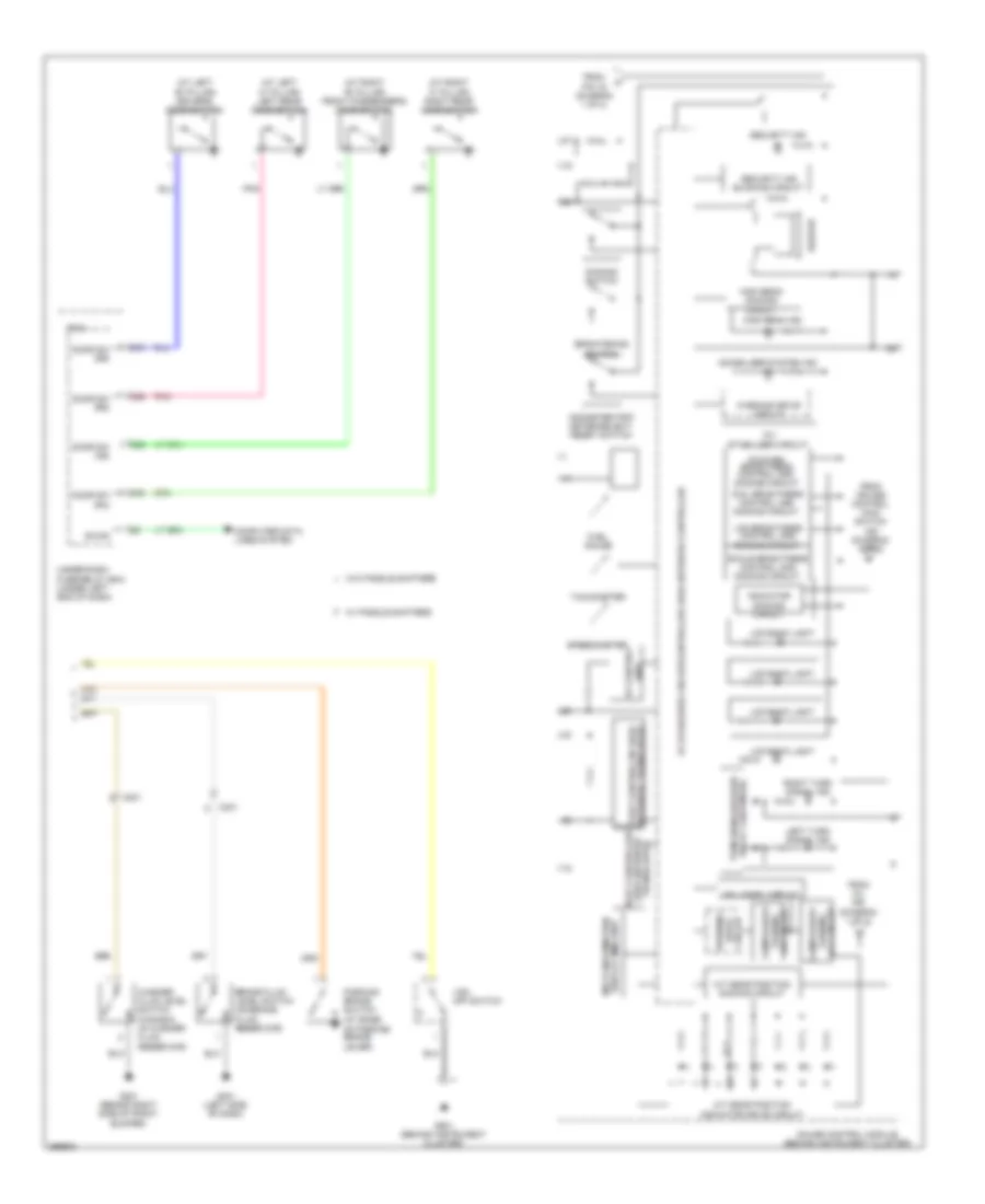
Instrument Cluster Wiring Diagram, Except Electric Vehicle (1 of 2) for Honda Fit EV 2014
 https://portal-diagnostov.com/license.html
Automotive Electricians Portal FZCO
Automotive Electricians Portal FZCO
https://portal-diagnostov.com/license.html
https://portal-diagnostov.com/license.html
Automotive Electricians Portal FZCO
Automotive Electricians Portal FZCOList of elements for Instrument Cluster Wiring Diagram, Except Electric Vehicle (1 of 2) for Honda Fit EV 2014:
- +b backup
- 10a
- 5v stabilizer circuit/controller area network controller
- 7.5a
- Abs ind
- Brake system ind
- Can h
- Can l
- Charging system ind
- Compulsory
- Computer data lines system
- Coolant high temperature ind
- Coolant low temperature ind
- Cruise control ind
- Cruise control main switch ind
- Cruise control system
- Door/tailgate open ind
- Drl ind
- Ecm (left side of engine compt)
- Eps ind
- Exterior lights system
- Fog light ind
- Fuel gauge sending unit
- Fuel tank unit (in fuel tank)
- Fuse 1
- Fuse 22
- G501 (behind instrument cluster)
- Gauge control module (behind instrument cluster)
- Hot at all times
- Hot in on or start
- Ig1 meter
- Interior lights system
- J/c c502 (left side of dash)
- J/c c504 (left side of dash)
- Lights on ind
- Low fuel ind
- Low oil pressure ind
- Low tire pressure ind
- Maintenance required ind
- Micu
- Mil ind
- Oil pressure switch (near oil filter)
- Pnk
- Red
- Seat belt reminder ind
- Side air bag cut-off ind
- Srs ind
- Sw i/p
- Tan
- To indicator dimming circuit (diagram 2 of 2)
- To security ind (diagram 2 of 2)
- Tpms ind
- Turning off circuit (diagram 2 of 2)
- Under-dash fuse/relay box (under left end of dash)
- Vsa off ind
- Vsa system ind
- Warning drive circuit
- Washer fluid level ind
Instrument Cluster Wiring Diagram, Except Electric Vehicle (2 of 2) for Honda Fit EV 2014
 https://portal-diagnostov.com/license.html
Automotive Electricians Portal FZCO
Automotive Electricians Portal FZCO
https://portal-diagnostov.com/license.html
https://portal-diagnostov.com/license.html
Automotive Electricians Portal FZCO
Automotive Electricians Portal FZCOList of elements for Instrument Cluster Wiring Diagram, Except Electric Vehicle (2 of 2) for Honda Fit EV 2014:
- (at left "b" pillar) driver's door switch
- (at left "c" pillar) left rear door switch
- (at right "b" pillar) front passenger's door switch
- (at right "c" pillar) right rear door switch
- -off circuit turning
- 10v stabilizer circuit
- 5v stabilizer circuit/controller area network controller
- A/t gear position dimming circuit
- A/t gear position indicator drive circuit
- B-can
- Beeper
- Body controller area network transceiver
- Brake fluid level switch (on brake fluid reservoir)
- Brightening switch
- C201
- C26
- C301
- C32
- C33
- C40
- Circuit
- Compulsory
- Computer data lines system
- Dial brightness control and dimming circuit
- Dimming switch
- Display (mid) unit multi-information
- Door sw (as)
- Door sw (dr)
- Door sw (ra)
- Door sw (rd)
- Drive circuit
- Fail-safe
- From cruise control main switch ind (diagram 1 of 2)
- From mil ind (diagram 1 of 2)
- From pin 16 (diagram 1 of 2)
- Fuel gauge
- G201 (behind right side of front bumper)
- G401 (left side of dash)
- G501 (behind instrument cluster)
- Gauge control module (behind instrument cluster)
- High beam dimming circuit
- High beam ind
- Immobilizer system ind
- Indicator dimming circuit
- Lcd back light
- Lcd brightness control and dimming circuit
- Left turn signal ind
- Lever)
- Micu
- Network transceiver fast controller area
- Odometer/trip meter/select/ reset switch
- Parking brake switch (at base of parking brake
- Pnk
- Pointer brightness control and dimming circuit
- Relay 2 (sounder) turn signal/hazard
- Right turn signal ind
- Scale brightness control and dimming circuit
- Security ind
- Security ind blinking circuit
- Speedometer
- Tachometer
- Turning -on circuit
- Under-dash fuse/relay box (under left end of dash)
- Unit 5v control
- Vsa off switch
- W/ paddle shifters
- W/o paddle shifters
- Warning
- Warning drive circuit
- Washer fluid level switch (canada) (in washer fluid reservoir)

 Čeština
 Dansk
Dansk Deutsch
 Ελληνικά
 English
 English
 Español
 Suomi
Suomi Français
 Français
 עברית
עברית Hrvatski
 Magyar
 Italiano
 한국어
한국어 Nederlands
 Polski
 Português
 Português
 Română
 Русский
 Slovenčina
 Slovenščina
 Svenska
 Türkçe
 中文 (中国)
