POWER DISTRIBUTION
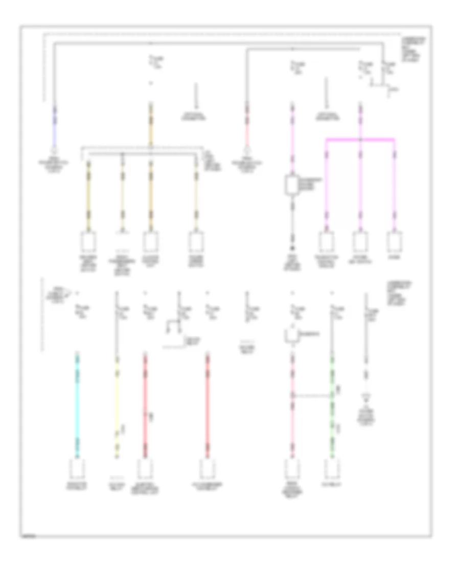
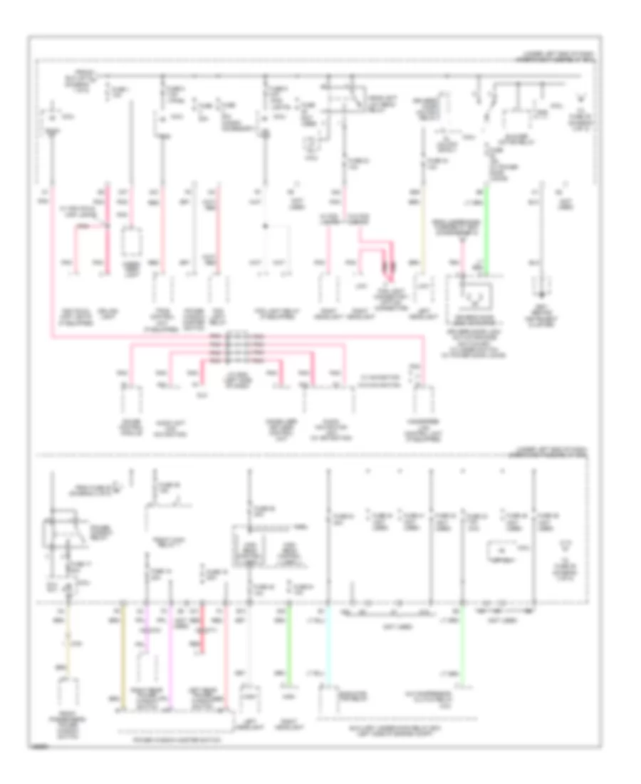
Power Distribution Wiring Diagram, Electric Vehicle (1 of 4) for Honda Fit EV 2014
 https://portal-diagnostov.com/license.html
Automotive Electricians Portal FZCO
Automotive Electricians Portal FZCO
https://portal-diagnostov.com/license.html
https://portal-diagnostov.com/license.html
Automotive Electricians Portal FZCO
Automotive Electricians Portal FZCO
List of elements for Power Distribution Wiring Diagram, Electric Vehicle (1 of 4) for Honda Fit EV 2014:
- A27
- A32
- A35
- Ab3
- B20
- B30
- B32
- Battery
- Battery terminal fuse box (on battery)
- Blower motor relay
- Brake pedal position switch
- Busbar a
- C306
- C314
- C315
- C316
- C317
- C320
- C321
- Charge lid relay
- D33
- D37
- D38
- D43
- D44
- Driver's door lock actuator/ knob switch
- Driver's seat heater relay (high)
- Driver's seat heater relay (low)
- Eps control unit
- From lighting a
- Front passenger's door lock actuator/ knob switch
- Front passenger's seat heater relay (high)
- Front passenger's seat heater relay (low)
- Fuse 100a
- Fuse 10a
- Fuse 15a
- Fuse 20a
- Fuse 30a
- Fuse 7.5a
- Fuse 70a
- Hazard warning switch
- Horn relay
- Ighldb1 relay
- Left headlight bulb
- Left rear door lock actuator/ knob switch
- Lighting relay
- Micu
- N10
- Pnk
- Power control unit
- Power window master switch
- Power window relay
- Q31
- Red
- Relay (diagram 1 of 4)
- Right headlight bulb
- Right rear door lock actuator/ knob switch
- Selectable unlock relay
- T13
- Tailgate lock actuator
- To auxiliary under-hood fuse box (diagram 4 of 4)
- To fuse 1 (diagram 4 of 4)
- To fuse 2 (diagram 1 of 4)
- Tpms control unit
- Under- dash fuse/ relay box (under left end of dash)
- Under-dash fuse/relay box (under left end of dash)
- Vsa modulator- control unit
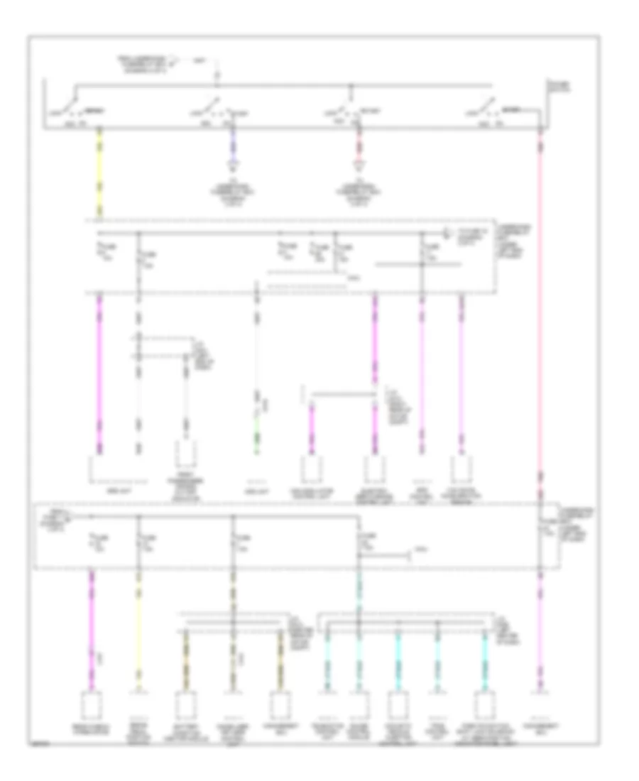
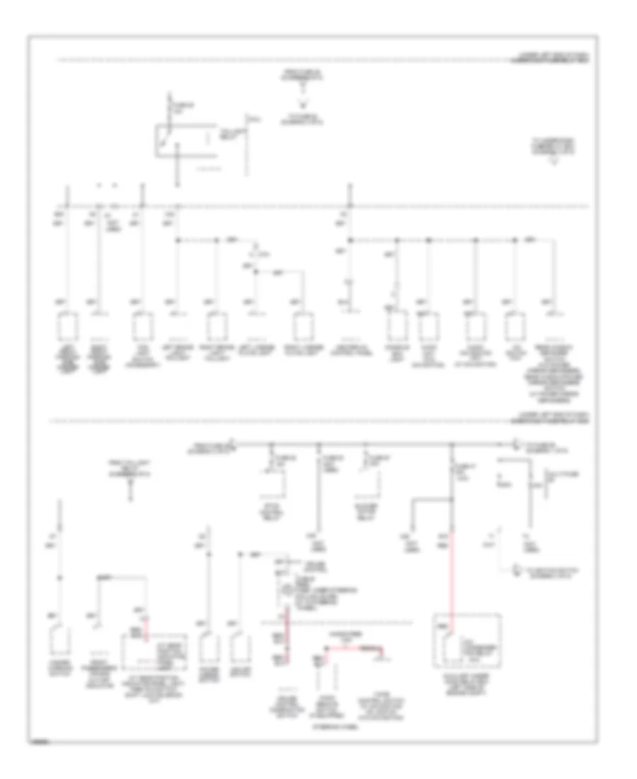
Power Distribution Wiring Diagram, Electric Vehicle (2 of 4) for Honda Fit EV 2014
 https://portal-diagnostov.com/license.html
Automotive Electricians Portal FZCO
Automotive Electricians Portal FZCO
https://portal-diagnostov.com/license.html
https://portal-diagnostov.com/license.html
Automotive Electricians Portal FZCO
Automotive Electricians Portal FZCOList of elements for Power Distribution Wiring Diagram, Electric Vehicle (2 of 4) for Honda Fit EV 2014:
- (optional connector)
- A/c condenser fan relay
- A/c main relay
- A24
- Ab1
- Ab2
- Ac1
- Ac2
- Accessory power socket
- B33
- B34
- Busbar b
- C305
- C308
- C314
- Climate control unit
- D46
- D47
- Diode
- Driver's seat heater switch
- Electric servo brake control unit
- From fuse 27 d (diagram 4 of 4)
- From power switch (diagram 3 of 4)
- Front passenger's seat heater switch
- Fuse 20a
- Fuse 30a
- Fuse 60-1 40a
- Fuse 60-2 50a
- Fuse 7.5a
- G202 (left center of dash)
- Ighlda relay
- Ighldb2 relay
- J/c c008 (left center of dash)
- M/c relay
- Micu
- Pnk
- Power key switch
- Power mirror switch
- Q34
- Radiator fan relay
- Rear window defogger relay
- Red
- Telematics control module
- To power switch (diagram 3 of 4)
- Under-dash fuse/relay box (under left end of dash)
- Y11
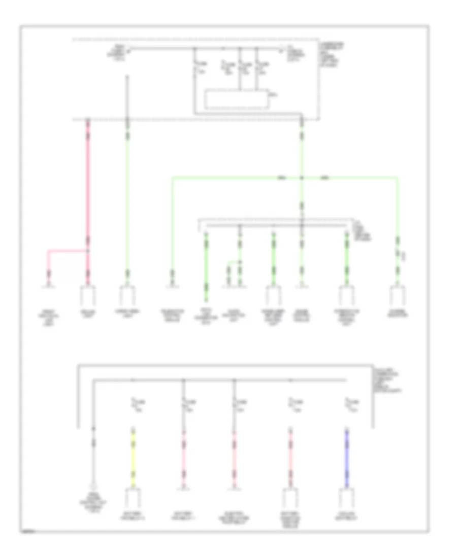
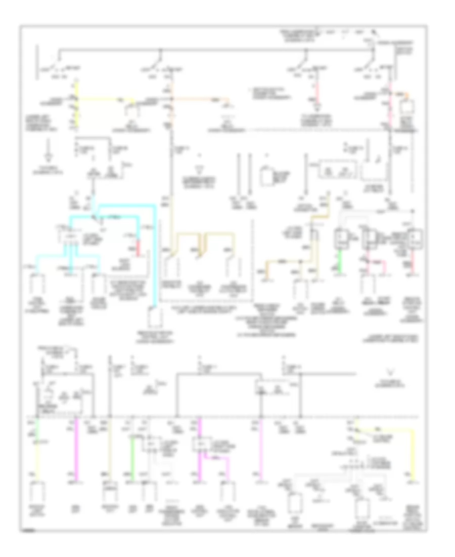
Power Distribution Wiring Diagram, Electric Vehicle (3 of 4) for Honda Fit EV 2014
 https://portal-diagnostov.com/license.html
Automotive Electricians Portal FZCO
Automotive Electricians Portal FZCO
https://portal-diagnostov.com/license.html
https://portal-diagnostov.com/license.html
Automotive Electricians Portal FZCO
Automotive Electricians Portal FZCOList of elements for Power Distribution Wiring Diagram, Electric Vehicle (3 of 4) for Honda Fit EV 2014:
- A11
- A14
- A16
- A38
- A39
- Aa19
- Acc
- Acc on
- Acoustic vehicle alerting control unit
- Ad1
- Ae2
- B12
- B18
- Battery condition monitor module
- Brake pedal position switch
- C10
- C314
- C317
- C319
- D23
- Electric servo brake control unit
- Eps control unit
- From fuse 11 f (diagram 3 of 4)
- From under-dash fuse/relay box (diagram 2 of 4)
- Front passenger's air bag cut-off indicator
- Fuse 10a
- Fuse 15a
- Fuse 30a
- Fuse 7.5a
- Gauge control module
- Immobilizer- keyless control unit
- J/c c001 (left end of dash)
- J/c c006 (left center of dash)
- J/c c010 (right rear of motor compt)
- J/c c012 (center rear of motor compt)
- Lock
- Management ecu
- Micu
- Ods unit
- On acc
- Park pin switch/ shift lock solenoid/ a/t gear position indicator panel light
- Pnk
- Power switch
- Rear window wiper motor
- Red
- Srs unit
- Start
- Telematics control unit
- To fuse 16 (diagram 3 of 4)
- To under-dash fuse/relay box (diagram 2 of 4)
- Tpms control unit
- Under-dash fuse/relay box (under left end of dash)
- Vsa modulator control unit
- Yaw rate- acceleration sensor
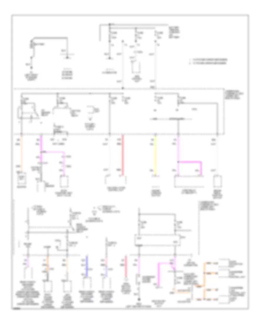
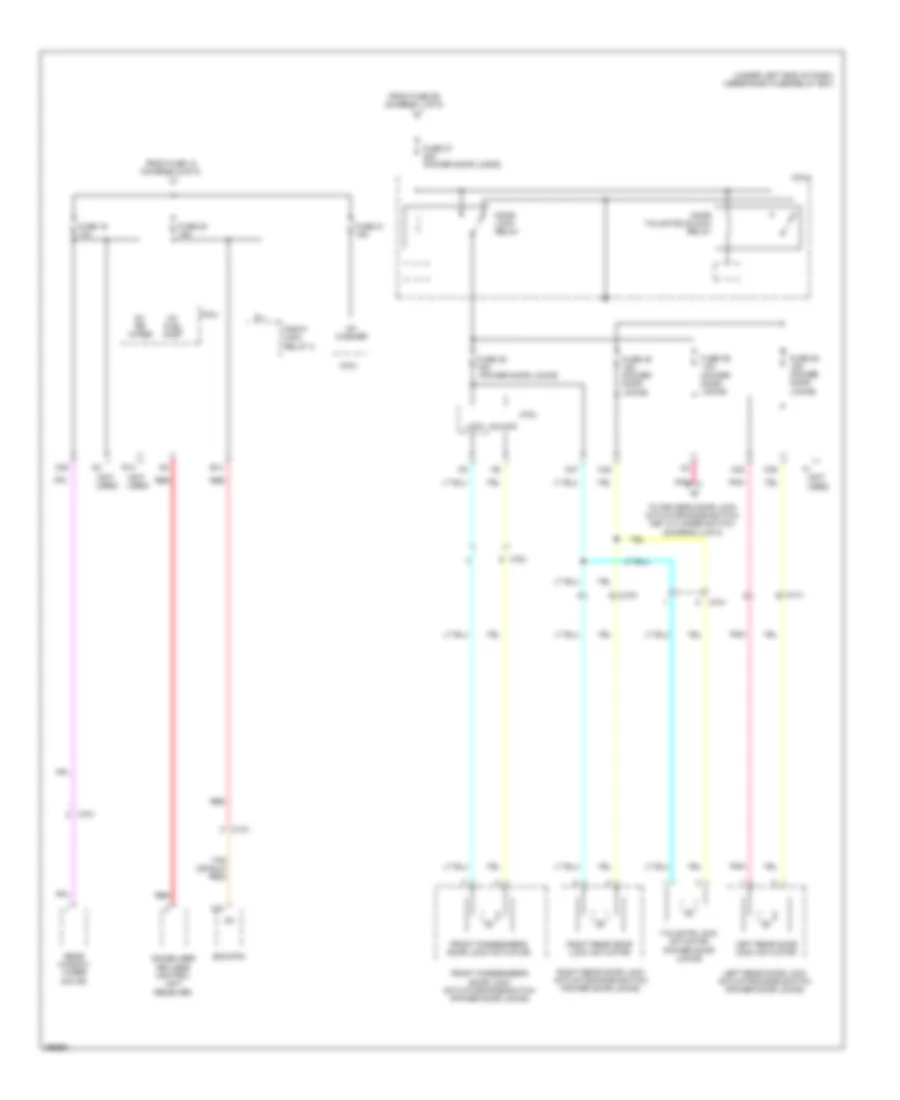
Power Distribution Wiring Diagram, Electric Vehicle (4 of 4) for Honda Fit EV 2014
 https://portal-diagnostov.com/license.html
Automotive Electricians Portal FZCO
Automotive Electricians Portal FZCO
https://portal-diagnostov.com/license.html
https://portal-diagnostov.com/license.html
Automotive Electricians Portal FZCO
Automotive Electricians Portal FZCOList of elements for Power Distribution Wiring Diagram, Electric Vehicle (4 of 4) for Honda Fit EV 2014:
- A17
- Audio- navigation unit
- Auxiliary under-hood fuse box (left side of motor compt)
- Battery condition monitor module
- Battery fan relay 1
- Battery fan relay 2
- C314
- Cargo area light
- Ceiling light
- Charge indicator
- Cooling ewp relay
- D10
- D42
- Data link connector (dlc)
- Electric heater water pump relay
- From fuse 3 b (diagram 1 of 4)
- From power control unit (diagram 1 of 4)
- Front individual map light
- Fuse 10a
- Fuse 15a
- Fuse 20a
- Fuse 30a
- Fuse 7.5a
- Gauge control module
- Immobilizer- keyless control unit
- Interactive remote control unit
- J/c c008 (left center of dash)
- Micu
- Pnk
- Red
- Telematics control module
- To fuse 30 (diagram 2 of 4)
- Under-dash fuse/relay box (under left end of dash)
Power Distribution Wiring Diagram, Except Electric Vehicle (1 of 5) for Honda Fit EV 2014
 https://portal-diagnostov.com/license.html
Automotive Electricians Portal FZCO
Automotive Electricians Portal FZCO
https://portal-diagnostov.com/license.html
https://portal-diagnostov.com/license.html
Automotive Electricians Portal FZCO
Automotive Electricians Portal FZCOList of elements for Power Distribution Wiring Diagram, Except Electric Vehicle (1 of 5) for Honda Fit EV 2014:
- (not used)
- (option connector)
- 30a
- A/f sensor
- A/f sensor relay
- A11
- A14
- A22
- A23
- A27
- Acc
- Accessory power socket
- Alternator
- Audio navigation unit
- Audio unit
- Auxiliary under-dash fuse box (under left end of dash)
- B19
- B23
- B28
- Battery
- Battery terminal fuse box (on battery)
- Brake pedal position switch
- C101
- C20
- C204
- C303
- C43
- C602
- C701
- C761
- Cigar
- Coil
- Ecm/pcm
- Eld unit
- Eps control unit
- Evap canister vent shut valve
- From fuse 10 (diagram 4 of 5)
- From ignition switch (diagram 4 of 5)
- From multi- fuse 60 (diagram 3 of 5)
- Fuse 100a
- Fuse 10a
- Fuse 15a
- Fuse 20a
- Fuse 30a
- Fuse 31 (not used)
- Fuse 54 20a
- Fuse 55 10a
- Fuse 59 20a
- Fuse 7.5a
- Fuse 70a
- G1 (left front of engine compt)
- G502 (left center of dash)
- H/mirr
- Handsfree link control unit
- Handsfree link control unit (if equipped)
- Haz
- Hazard warning switch
- Horn relay (w/ security)
- Ignition coil relay
- Ignition key switch (a/t)
- Left power mirror (w/ power mirror defoggers)
- M18
- Micu
- Nca
- Rear window defogger (w/ power mirror defoggers)
- Rear window defogger (w/o power mirror defoggers)
- Rear window defogger relay
- Rear window defogger switch (w/o power mirror defoggers) rear window/power mirror defoggers switch (w/ power mirror defoggers)
- Red
- Right power mirror (w/ power mirror defoggers)
- Rr def
- Starter
- Starter solenoid
- Stop & horn
- Sub- rly
- To fuse 1 (diagram 2 of 5)
- To fuse 27 (diagram 5 of 5)
- Under-dash fuse/relay box (under left end of dash)
- Vsa modulator- control unit
- W/ navigation
- W/ power mirror defoggers
- W/o navigation
- W/o power mirror defoggers
Power Distribution Wiring Diagram, Except Electric Vehicle (2 of 5) for Honda Fit EV 2014
 https://portal-diagnostov.com/license.html
Automotive Electricians Portal FZCO
Automotive Electricians Portal FZCO
https://portal-diagnostov.com/license.html
https://portal-diagnostov.com/license.html
Automotive Electricians Portal FZCO
Automotive Electricians Portal FZCOList of elements for Power Distribution Wiring Diagram, Except Electric Vehicle (2 of 5) for Honda Fit EV 2014:
- (a/c)
- (fog
- (if equipped)
- (not used)
- (tpms)
- (under left end of dash) under-dash fuse/relay box
- +b p/w as
- 20a
- A/c compressor
- A22
- A24
- A30
- Audio unit (w/o navigation)
- Audio- navigation unit (w/ navigation)
- Auxiliary under-hood relay box (left side of engine compt)
- B13
- B29
- Back up
- Blower motor relay
- C12
- C31
- C37
- C761
- C771
- C781
- Cargo area light
- Ceiling light
- Clutch relay
- Dl unlock dr rly
- Dlc
- Driver's door lock actuator
- Driver's door lock actuator/knob switch/key cylinder switch (w/ power door locks)
- Driver's door unlock relay
- Fog light connector 1 (option connector)
- Fog light relay
- Fog light relay (if equipped)
- Fr fog
- From eld unit a (diagram 1 of 5)
- From fuse 25 b (diagram 2 of 5)
- From under-dash fuse/relay box (diagram 5 of 5)
- Front passenger's power window switch
- Fuse
- Fuse 1 10a
- Fuse 15a (w/ power door locks)
- Fuse 17 20a
- Fuse 18 20a
- Fuse 19 20a
- Fuse 2 7.5a
- Fuse 20a (honda accessory)
- Fuse 28 20a
- Fuse 30 30a
- Fuse 32 10a
- Fuse 34 10a
- Fuse 39 15a
- Fuse 40
- Fuse 41
- Fuse 42
- Fuse 43 7.5a
- Fuse 45
- Fuse 46
- Fuse 48 10a
- Fuse 51 10a
- Fuse 9 20a
- G501 (behind instrument cluster)
- Gauge control module
- Gnd
- H/l lo rly
- Handsfree link control unit (if equipped)
- Headlight low beam relay
- High
- High beam control unit
- Immobilizer keyless control unit
- Individual map lights (if equipped)
- J/c c502 (left side of dash)
- Left headlight
- Left rear power window switch
- Lights)
- Low
- M21
- Map lights
- Micu
- Option
- P/w rly
- Pgm-f1 main relay 1
- Pnk
- Power window master switch
- Power window relay
- Radiator fan relay
- Red
- Right headlight
- Right rear power window switch
- To fuse 29 (diagram 3 of 5)
- To fuse 39 (diagram 2 of 5)
- Tpms
- Tpms control unit
- W/ fog lights
- W/ individual
- W/ navigation
- W/o fog lights
- W/o navigation
Power Distribution Wiring Diagram, Except Electric Vehicle (3 of 5) for Honda Fit EV 2014
 https://portal-diagnostov.com/license.html
Automotive Electricians Portal FZCO
Automotive Electricians Portal FZCO
https://portal-diagnostov.com/license.html
https://portal-diagnostov.com/license.html
Automotive Electricians Portal FZCO
Automotive Electricians Portal FZCOList of elements for Power Distribution Wiring Diagram, Except Electric Vehicle (3 of 5) for Honda Fit EV 2014:
- (a/c)
- (not used)
- (under left end of dash) under-dash fuse/relay box
- 40a
- 50a
- A/c
- A/c condenser fan relay
- A/t gear position indicator panel light
- A/t gear position indicator panel light/ park pin switch/ shift lock solenoid (a/t)
- A13
- A36
- Audio remote switch (if equipped)
- Audio unit (w/o navigation)
- Audio- navigation unit (w/ navigation)
- Auxiliary under- hood relay box (left side of engine compt)
- B10
- B15
- B30
- Blower motor relay
- C42
- C49
- C701
- Cable reel (a&b: under steering column cover) (c: in steering wheel)
- Console box light
- Control panel
- Cruise control
- Cruise control combination switch
- Etcs control relay
- Fog light switch (accessory)
- From fuse 29 e (diagram 3 of 5)
- From fuse 46 (diagram 2 of 5)
- From taillight relay (diagram 3 of 5)
- Front passenger's air bag cut-off indicator
- Fuse 29 10a
- Fuse 47 30a
- Fuse 52 15a
- Fuse 53
- Fuse 57 30a
- Hands free link
- Hazard warning switch
- Heater-a/c
- Left brake light/ taillight
- Left front parking/ side marker light
- Left license
- Micu
- Multi-fuse
- Plate light
- Power mirror switch
- Rear window defogger switch (w/o power mirror defoggers) rear window/power mirror defoggers switch (w/ power mirror defoggers)
- Red
- Right brake light/ taillight
- Right front parking/ side marker light
- Right license
- Steering wheel
- Switch (a/c)
- Taillight relay
- To fuse 52 (diagram 3 of 5)
- To fuse 59 (diagram 1 of 5)
- To ignition switch (diagram 4 of 5)
- To under-dash fuse/relay box (diagram 3 of 5)
- Voice control switch (w/ navigation) hfl switch (w/o navigation)
- Vsa off switch
Power Distribution Wiring Diagram, Except Electric Vehicle (4 of 5) for Honda Fit EV 2014
 https://portal-diagnostov.com/license.html
Automotive Electricians Portal FZCO
Automotive Electricians Portal FZCO
https://portal-diagnostov.com/license.html
https://portal-diagnostov.com/license.html
Automotive Electricians Portal FZCO
Automotive Electricians Portal FZCOList of elements for Power Distribution Wiring Diagram, Except Electric Vehicle (4 of 5) for Honda Fit EV 2014:
- (a/t)
- (honda accessory)
- (not used)
- (option connector)
- (under left end of dash) under-dash fuse/relay box
- 40a
- A/c compressor clutch relay (a/c)
- A/c condenser fan relay (a/c)
- A/c switch (a/c)
- A/t
- A/t gear position indicator panel light/park pin switch/shift lock solenoid
- A/t reverse relay
- A26
- A27
- A31
- A32
- A33
- Acc
- Alternator
- Auxiliary under-hood relay box (left side of engine compt)
- B10
- B11
- B12
- B17
- B25
- Backup light switch
- Blower motor relay
- Brake pedal position switch (w/ cruise control)
- C101
- C603
- Connector (honda accessory)
- Day lt
- E10
- Ecm/pcm (a/t)
- Eld
- Eps control unit
- Evap canister purge valve
- From fuse 22 k (diagram 4 of 5)
- From under-dash g fuse/relay box (diagram 3 of 5)
- Front passenger's air bag cut-off indicator
- Fuse 10 7.5a
- Fuse 11 7.5a
- Fuse 12 10a
- Fuse 15 7.5a
- Fuse 22 7.5a
- Fuse 44 7.5a
- Fuse 5 10a
- Fuse 56 30a
- Fuse 6 10a
- Fuse 7 10a
- Fuse 8 7.5a
- Gauge control module
- Honda accessory
- Ig 1 fuse
- Ig 1 relay
- Ig 1 relay (honda accessory)
- Ig 2 relay
- Ig 2 relay (honda accessory)
- Ig 2/ start fuse
- Ig1
- Ig1 abs
- Ig1 acg
- Ig1 back lt
- Ig1 fr
- Ig1 srs
- Ig2
- Ig2 hac
- Ignition switch
- J/c c103 (top rear of engine)
- J/c c205 (right side of dash)
- J/c c502 (left side of dash)
- J/c c504 (left side of dash)
- Lock
- M/t
- M27
- Maf/ iat sensor
- Meter
- Micu
- Ods unit
- On acc
- Opds
- Pnk
- Pnk x3
- Power mirror switch
- Q12
- Q14
- Q16
- Radiator fan relay
- Rear window defogger switch (w/o power mirror defoggers) rear window/power mirror defoggers switch (w/ power mirror defoggers)
- Red
- Remote starting control unit
- Remote starting control unit (honda accessory)
- Remote starting control unit in-line fuse
- Secondary ho2s
- Shift lock solenoid
- Srs unit
- Start
- Start relay
- Start relay (honda accessory)
- Starter cut relay
- To fuse 20 (diagram 5 of 5)
- To fuse 6 (diagram 4 of 5)
- To rear window defogger relay (diagram 1 of 5)
- To under-dash fuse/relay box (diagram 1 of 5)
- Tpms control unit (if equipped)
- Under-dash fuse/relay box (under left end of dash)
- Unit
- Vbsol
- Vsa modulator control unit
- W/ cruise control
- Wiper
- Yaw rate-lateral acceleration sensor (w/ vsa)
Power Distribution Wiring Diagram, Except Electric Vehicle (5 of 5) for Honda Fit EV 2014
 https://portal-diagnostov.com/license.html
Automotive Electricians Portal FZCO
Automotive Electricians Portal FZCO
https://portal-diagnostov.com/license.html
https://portal-diagnostov.com/license.html
Automotive Electricians Portal FZCO
Automotive Electricians Portal FZCOList of elements for Power Distribution Wiring Diagram, Except Electric Vehicle (5 of 5) for Honda Fit EV 2014:
- (not
- (not used)
- (power door locks)
- (under left end of dash) under-dash fuse/relay box
- B14
- C10
- C101
- C35
- C36
- C39
- C47
- C48
- C701
- C761
- C771
- C781
- Door lock relay
- Door tailgate/unlock relay
- Ecm/pcm
- From fuse 12 (diagram 4 of 5)
- From fuse 59 (diagram 1 of 5)
- Front passenger's door lock actuator
- Front passenger's door lock actuator/knob switch (power door locks)
- Fuse 16 10a
- Fuse 20 15a
- Fuse 21 15a
- Fuse 27 30a (power door locks)
- Fuse 35 15a
- Fuse 36 15a (power door locks)
- Fuse 49 15a (power door locks)
- Fuse 50 15a (power door locks)
- Ig1
- Ig1 fuel pump
- Ig1 rr wiper
- Immobilizer keyless control unit receiver
- Left rear door lock actuator
- Left rear door lock actuator/knob switch (power door locks)
- Lock
- Micu
- Pgm-fi main relay 2
- Pnk
- R14
- Rear window wiper motor
- Red
- Right rear door lock actuator
- Right rear door lock actuator/knob switch (power door locks)
- Tailgate lock actuator (power door locks)
- To driver's door lock actuator/knob switch/ key cylinder switch (diagram 2 of 5)
- Unlock
- Used)
- Washer

 Čeština
 Dansk
Dansk Deutsch
 Ελληνικά
 English
 English
 Español
 Suomi
Suomi Français
 Français
 עברית
עברית Hrvatski
 Magyar
 Italiano
 한국어
한국어 Nederlands
 Polski
 Português
 Português
 Română
 Русский
 Slovenčina
 Slovenščina
 Svenska
 Türkçe
 中文 (中国)
