TRANSMISSION
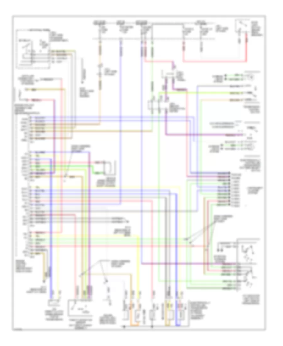
A/T Wiring Diagram for Lexus LS 400 1997
List of elements for A/T Wiring Diagram for Lexus LS 400 1997:
- (dash harness, right side of dash)
- 2 indic
- 3 indic
- A/t indicator light switch (left side of transmission)
- A/t oil temp
- A10
- B14
- B17
- Batt
- Cruise control ecu (behind right side of dash)
- D indic
- Data link connector 1 (top front of engine)
- E11
- E12
- E13
- E14
- E18
- Ect
- Efi fuse 20a
- Efi relay
- Electronically controlled transmission pattern select switch
- Electronically controlled transmission solenoid (in trans. valve body assembly)
- Engine control module (behind right side of dash)
- Engine coolant temperature sensor (on intake manifold)
- Eo1
- Eo2
- Eo3
- G100 (front side of left fender)
- G114 (rear side of left cylinder head)
- G117 (rear side of right cyl head)
- Gauge fuse 10a
- Hot at all times
- Hot in on or start
- Hot in start
- Idl1
- Ign fuse 10a
- Igsw
- Instrument cluster system
- Interior lights system
- J/b 1 (left side of dash)
- J/b 2 (left side of engine compartment)
- J/b 3 (behind combination meter)
- J/b 4 (left kick panel)
- J/c 4 (left side of dash)
- K11
- L indic
- L11
- Mrel
- Mt3
- Mtd
- N indic
- N0.3 (lock-up)
- Nco+
- Nco-
- No. 1
- No. 2
- No. 4
- Normal
- Nssd
- Nsw
- O/d direct clutch speed sensor (top of transmission)
- Oil
- P indic
- Power
- Pwr
- Pwr ind
- Pwrl
- R indic
- Red
- Sln+
- Sln-
- Slu+
- Slu-
- Sp2+
- Sp2-
- Starter fuse 7.5a
- Starting/ charging system
- Stop light switch (brake pedal bracket)
- Stop lp fuse 25a
- Stop s fuse 5a
- Te1
- Throttle position sensor (on throttle body assembly)
- Thw
- Transmission control switch
- Vehicle speed sensor (trans. output shaft housing)
- Vta1
- W/air suspension
- W/o air suspension
 Čeština
 Dansk
Dansk Deutsch
 Ελληνικά
 English
 English
 Español
 Suomi
Suomi Français
 Français
 עברית
עברית Hrvatski
 Magyar
 Italiano
 한국어
한국어 Nederlands
 Polski
 Português
 Português
 Română
 Русский
 Slovenčina
 Slovenščina
 Svenska
 Türkçe
 中文 (中国)
 日本語
日本語