AIR CONDITIONING
2.0L
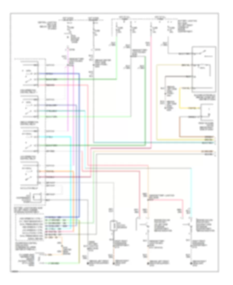
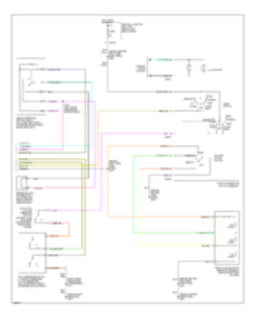
2.0L, Manual A/C Wiring Diagram (1 of 2) for Ford Escape 2002
 https://portal-diagnostov.com/license.html
Automotive Electricians Portal FZCO
Automotive Electricians Portal FZCO
https://portal-diagnostov.com/license.html
https://portal-diagnostov.com/license.html
Automotive Electricians Portal FZCO
Automotive Electricians Portal FZCO
List of elements for 2.0L, Manual A/C Wiring Diagram (1 of 2) for Ford Escape 2002:
- (behind left front radiator support) g104
- (behind left side dash panel) s221
- (behind right headlamp) g102
- (behind right headlamp) g103
- (near battery junction box (bjb)) s127
- (near battery junction box (bjb)) s131 (or s132)
- (near battery junction box (bjb)) s132
- (near battery junction box (bjb)) s144
- (right front side engine compartment) s116
- A/c clutch relay
- A/c clutch rly ctrl
- A/c clutch solenoid
- A/c compressor clutch diode
- Battery junction box (bjb) (on left front corner of engine compartment)
- Blower motor relay (behind lower left center of dash)
- C270b
- C270c
- Central junction box (cjb) (below left end of dash)
- Cyl temp sensor input
- Cylinder head temperature sensor (on right front of cylinder head)
- Dual pressure sw sig
- Engine cooling fan motor 1 (on left side of engine compartment, behind radiator)
- Engine cooling fan motor 2 (on right side of engine compartment, behind radiator)
- Front blower motor (behind right side of dash)
- Fuse 15a
- Fuse 3a
- Fuse 40a
- Fuse 5a
- High speed fan control relay 1
- High speed rly ctrl 1
- Hot at all times
- Hot in run or start
- Low speed fan control relay
- Low speed rly ctrl
- Med speed rly ctrl
- Medium speed fan control relay
- Pcm module power diode
- Powertrain control module (pcm) (in recess on upper center of firewall)
- S100 (center rear engine)
- Signal return
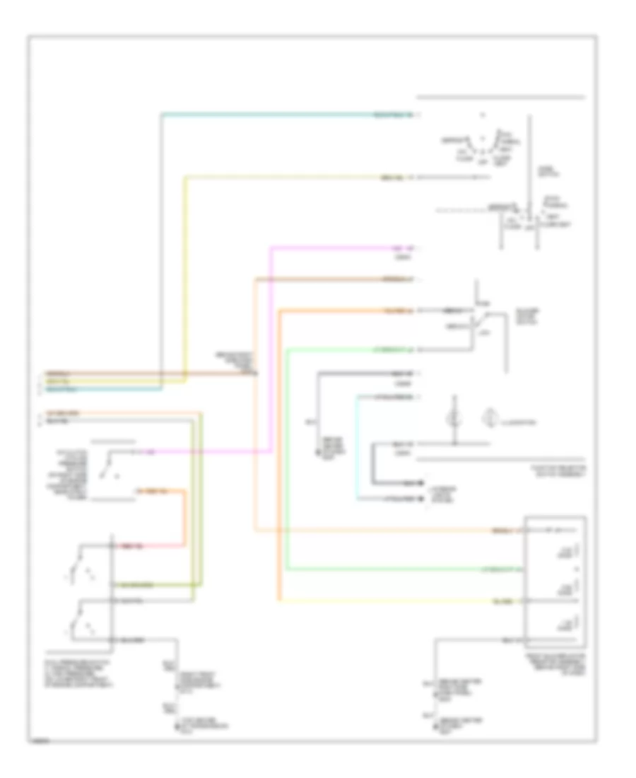
2.0L, Manual A/C Wiring Diagram (2 of 2) for Ford Escape 2002
 https://portal-diagnostov.com/license.html
Automotive Electricians Portal FZCO
Automotive Electricians Portal FZCO
https://portal-diagnostov.com/license.html
https://portal-diagnostov.com/license.html
Automotive Electricians Portal FZCO
Automotive Electricians Portal FZCOList of elements for 2.0L, Manual A/C Wiring Diagram (2 of 2) for Ford Escape 2002:
- (behind center of dash) g200
- (behind center of dash) g201
- (behind right side dash panel) s200
- (right front side engine compartment) s114
- (top center of transmission) g101
- 0.33 ohms
- 0.62 ohms
- 1.38 ohms
- A/c clutch cycling pressure switch (on right side of engine compartment, near strut tower)
- Blower motor switch
- C294a
- C294b
- C294c
- Defrost
- Dual pressure switch (1: normal pressure) (2: high pressure) (on lower right front of engine compartment)
- Floor
- Floor/ vent
- Floor/vent
- Front blower motor resistor assembly (behind right side of dash)
- Function selector switch assembly
- High
- Illumination
- Interior lights system
- Low
- Max
- Medium 1
- Medium 2
- Mix
- Mode switch
- Normal
- Off
- Right side dash panel) s203
- Vent
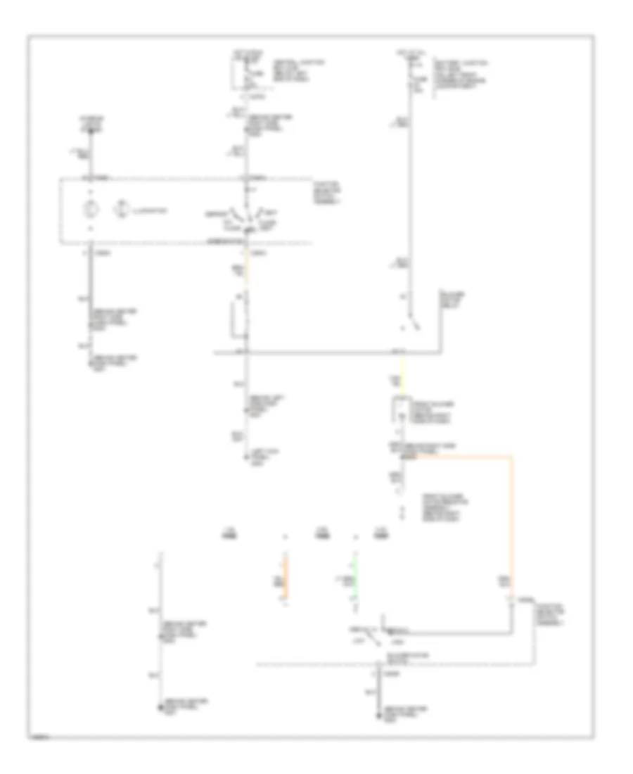
Heater Wiring Diagram for Ford Escape 2002
 https://portal-diagnostov.com/license.html
Automotive Electricians Portal FZCO
Automotive Electricians Portal FZCO
https://portal-diagnostov.com/license.html
https://portal-diagnostov.com/license.html
Automotive Electricians Portal FZCO
Automotive Electricians Portal FZCOList of elements for Heater Wiring Diagram for Ford Escape 2002:
- (behind center dash panel) g200
- (behind center dash panel) g201
- (behind center right side dash panel) s203
- (behind center right side, dash panel) s203
- (behind left side dash panel) s221
- (left kick panel) g202
- 0.33 ohms
- 0.62 ohms
- 1.38 ohms
- Battery junction box (bjb) (on left front corner of engine compartment)
- Blower motor relay
- Blower motor switch
- C270c
- C294a
- C294b
- C294c
- Central junction box (cjb) (below left end of dash)
- Defrost
- Floor
- Floor/ vent
- Front blower motor (behind right side of dash)
- Front blower motor resistor assembly (behind right side of dash)
- Function selector switch assembly
- Fuse 40a
- Fuse 5a
- High
- Hot at all times
- Hot in run or start
- Illumination
- Interior lights system
- Low
- Medium 1
- Medium 2
- Mix
- Mode switch
- Off
- Vent
3.0L
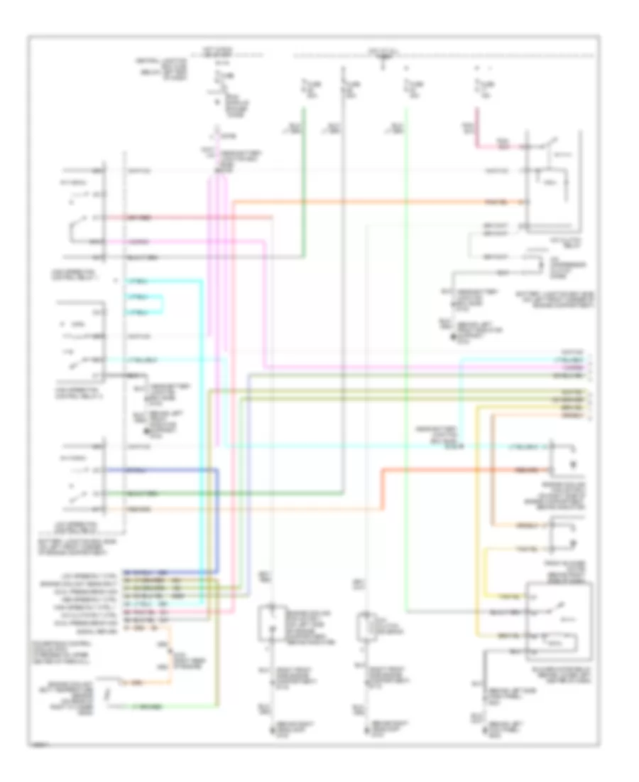
3.0L, Manual A/C Wiring Diagram (1 of 2) for Ford Escape 2002
 https://portal-diagnostov.com/license.html
Automotive Electricians Portal FZCO
Automotive Electricians Portal FZCO
https://portal-diagnostov.com/license.html
https://portal-diagnostov.com/license.html
Automotive Electricians Portal FZCO
Automotive Electricians Portal FZCOList of elements for 3.0L, Manual A/C Wiring Diagram (1 of 2) for Ford Escape 2002:
- (behind left front radiator support) g104
- (behind left side dash panel) s221
- (behind right headlamp) g102
- (behind right headlamp) g103
- (near battery junction box (bjb)) s128
- (near battery junction box (bjb)) s145
- (right front side engine compartment) s116
- 87a
- A/c clutch relay
- A/c clutch rly ctrl
- A/c clutch solenoid
- A/c compressor clutch diode
- Battery junction box (bjb) (on left front corner of engine compartment)
- Blower motor relay (behind lower left center of dash)
- C270b
- Central junction box (cjb) (below left end of dash)
- Dual pressure sw sig
- Engine coolant (ect) temperature sensor (on rear of right cylinder head)
- Engine coolant sens input
- Engine cooling fan motor 1 (on left side of engine compartment, behind radiator)
- Engine cooling fan motor 2 (on right side of engine compartment, behind radiator)
- Front blower motor (behind right side of dash)
- Front radiator support) g104
- Fuse 15a
- Fuse 3a
- Fuse 40a
- Fuse 50a
- High speed fan control relay 1
- High speed fan control relay 2
- High speed rly ctrl 1
- Hot at all times
- Hot in run or start
- Junction box (bjb)) s132
- Low speed fan control relay
- Low speed rly ctrl
- Med speed rly ctrl
- Pcm module power diode
- Powertrain control module (pcm) (in recess on upper center of firewall)
- Signal return
3.0L, Manual A/C Wiring Diagram (2 of 2) for Ford Escape 2002
 https://portal-diagnostov.com/license.html
Automotive Electricians Portal FZCO
Automotive Electricians Portal FZCO
https://portal-diagnostov.com/license.html
https://portal-diagnostov.com/license.html
Automotive Electricians Portal FZCO
Automotive Electricians Portal FZCOList of elements for 3.0L, Manual A/C Wiring Diagram (2 of 2) for Ford Escape 2002:
- (behind center dash panel) g200
- (behind center dash panel) g201
- (behind right headlamp) g103
- (behind right side dash panel) s200
- (right front side engine compartment) s114
- 0.33 ohms
- 0.62 ohms
- 1.38 ohms
- 87a
- A/c clutch cycling pressure switch (on right side of engine compartment, near strut tower)
- Blower motor switch
- C270c
- C294a
- C294b
- C294c
- Central junction box (cjb) (below left end of dash)
- Defrost
- Dual pressure switch (1: normal pressure) (2: high pressure) (on lower right front of engine compartment)
- Engine cooling fan resistor (on lower left side of engine compartment)
- Floor
- Floor/ vent
- Front blower motor resistor assembly (behind right side of dash)
- Function selector switch assembly
- Fuse 5a
- High
- Hot in run or start
- Illumination
- Interior lights system
- Low
- Max
- Medium 1
- Medium 2
- Medium speed fan control relay (on lower left front of engine compartment, near headlight)
- Mix
- Mode switch
- Normal
- Off
- Right side dash panel) s203
- S135 (left front side engine compartment)
- Vent
Heater Wiring Diagram for Ford Escape 2002
 https://portal-diagnostov.com/license.html
Automotive Electricians Portal FZCO
Automotive Electricians Portal FZCO
https://portal-diagnostov.com/license.html
https://portal-diagnostov.com/license.html
Automotive Electricians Portal FZCO
Automotive Electricians Portal FZCOList of elements for Heater Wiring Diagram for Ford Escape 2002:
- (behind center dash panel) g200
- (behind center dash panel) g201
- (behind center right side dash panel) s203
- (behind center right side, dash panel) s203
- (behind left side dash panel) s221
- (left kick panel) g202
- 0.33 ohms
- 0.62 ohms
- 1.38 ohms
- Battery junction box (bjb) (on left front corner of engine compartment)
- Blower motor relay
- Blower motor switch
- C270c
- C294a
- C294b
- C294c
- Central junction box (cjb) (below left end of dash)
- Defrost
- Floor
- Floor/ vent
- Front blower motor (behind right side of dash)
- Front blower motor resistor assembly (behind right side of dash)
- Function selector switch assembly
- Fuse 40a
- Fuse 5a
- High
- Hot at all times
- Hot in run or start
- Illumination
- Interior lights system
- Low
- Medium 1
- Medium 2
- Mix
- Mode switch
- Off
- Vent

 Čeština
 Dansk
Dansk Deutsch
 Ελληνικά
 English
 English
 Español
 Suomi
Suomi Français
 Français
 עברית
עברית Hrvatski
 Magyar
 Italiano
 한국어
한국어 Nederlands
 Polski
 Português
 Português
 Română
 Русский
 Slovenčina
 Slovenščina
 Svenska
 Türkçe
 中文 (中国)
