AIR CONDITIONING
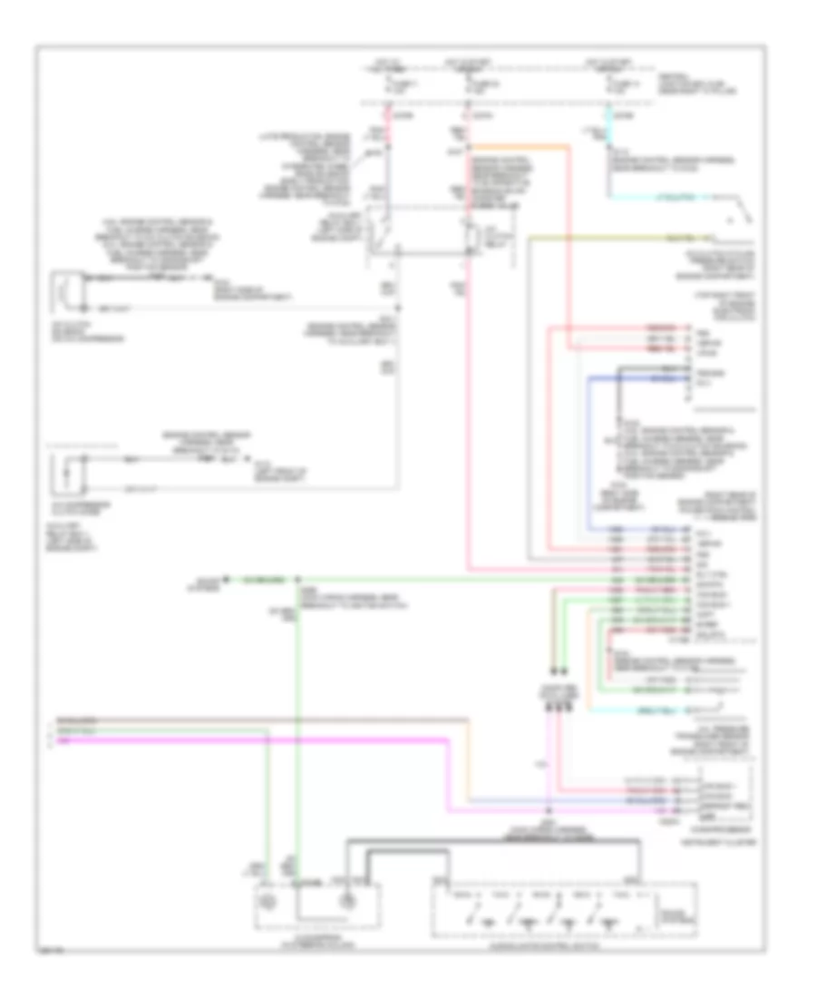
Automatic A/C Wiring Diagram (1 of 2) for Ford Pickup F150 2007
 https://portal-diagnostov.com/license.html
Automotive Electricians Portal FZCO
Automotive Electricians Portal FZCO
https://portal-diagnostov.com/license.html
https://portal-diagnostov.com/license.html
Automotive Electricians Portal FZCO
Automotive Electricians Portal FZCO
List of elements for Automatic A/C Wiring Diagram (1 of 2) for Ford Pickup F150 2007:
- (heater blower motor wiring harness, in breakout to c299)
- (in right front footwell) g203
- +/-
- Anti- theft system
- Autolamp/sunload sensor (top left side of dash)
- C228a
- C228b
- C270e
- C270g
- C3008b
- Central junction box (cjb) (near right "a" pillar)
- Defogger system
- Defrost req
- Electronic automatic temperature control (eatc) module (center of dash)
- Fresh/recirculation door actuator (behind right side of dash)
- Front blower motor (behind dash)
- Front blower motor relay
- Front blower motor speed controller (right "a" pillar)
- Fuse 116 30a
- Fuse 13 10a
- Fuse 5 7.5a
- G200 (left "a" pillar)
- Gnd
- High ind sig
- High/low on/off sig vref
- Hot at all times
- Hot in start or run
- In-vehicle temperature sensor (behind dash panel)
- Interior lights system
- Light sensor
- Low ind sig
- Low ind sig high/low on/off sig
- Mtr ctrl
- Panel mode actuator (behind center of dash)
- Pats ind
- Red
- Rly ctrl
- Rly sw pwr
- S202
- S204 (heater blower motor wiring harness, in breakout to c299)
- S208
- S208 (main wiring harness, near breakout to indicator flasher relay)
- S210 (main wiring harness, in breakout to electronic manual temperature control (emtc) module)
- S236 (main wiring harness)
- S286 (main wiring harness, near breakout to front blower motor speed controller)
- Seats system
- Sens
- Sig
- Sig rtn
- Sun sensor
- Temperature blend door actuator (behind center of dash)
- Ubp
- Vbatt
- Vehicle security module (left rear of cab)
- Vpwr
- Vref
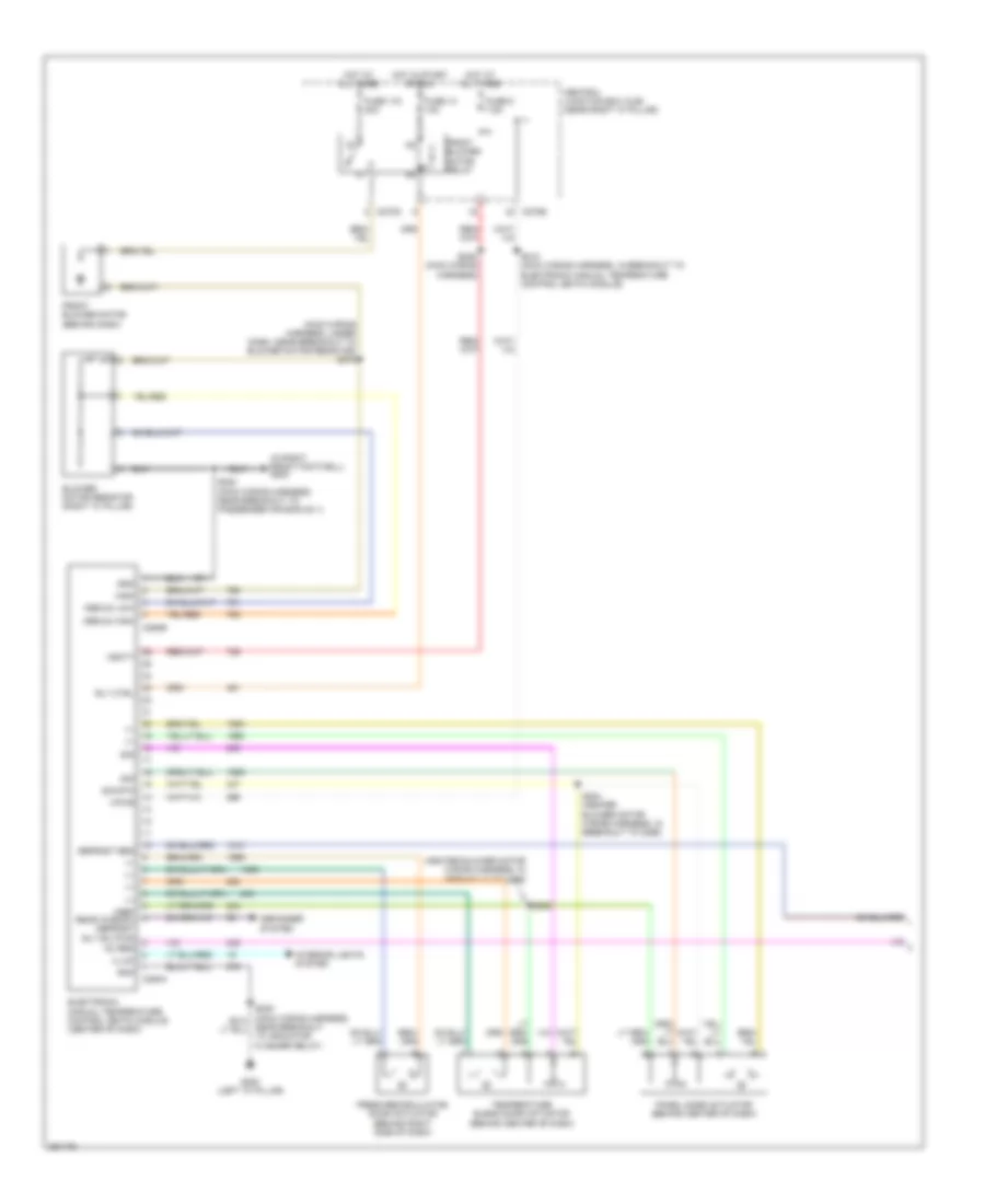
Automatic A/C Wiring Diagram (2 of 2) for Ford Pickup F150 2007
 https://portal-diagnostov.com/license.html
Automotive Electricians Portal FZCO
Automotive Electricians Portal FZCO
https://portal-diagnostov.com/license.html
https://portal-diagnostov.com/license.html
Automotive Electricians Portal FZCO
Automotive Electricians Portal FZCOList of elements for Automatic A/C Wiring Diagram (2 of 2) for Ford Pickup F150 2007:
- (4.6l: engine control sensor & fuel charge harness, near breakout to a/c clutch solenoid) (5.4l: engine control sensor & fuel charge harness, near breakout to crankshaft position sensor) s122
- (engine control sensor harness, near breakout to g102)
- (engine control sensor harness, near breakout to g110) s116
- (late production: engine control sensor harness, near breakout to integrated wheel ends solenoid) (early production: engine control sensor harness, near breakout to g102)
- (right rear of engine compartment) powertrain control module (pcm)
- (top right front of engine) electronic fan clutch
- A/c pressure transducer sensor (right front of engine compartment)
- A/c clutch cycling pressure switch (right rear of engine compartment)
- A/c clutch relay
- A/c clutch solenoid (on a/c compressor)
- A/c compressor clutch diode
- Acpt
- Audio/climate control switch
- Auxiliary relay box 1 (left side of engine compt)
- Breakout to a/c clutch solenoid) (5.4l: engine control sensor & fuel charge harness, near breakout to crankshaft position sensor)
- Bvref
- C175b
- C218b
- C220a
- C270a
- C270b
- Can bus +
- Can bus -
- Central junction box (cjb) (near right "a" pillar)
- Clockspring (in steering column)
- Computer data lines system
- Defrost req
- Fan+
- Fan-
- Fc-v
- Fss
- Fss-gnd
- Fuse 11 10a
- Fuse 14 10a
- Fuse 32 15a
- G104 (right side of engine compartment)
- G110 (left front of engine compt)
- Hot at all times
- Hot in start or run
- Instrument cluster
- Microprocessor
- Nca
- Rly ctrl
- S101 (engine control sensor harness, near breakout to auxiliary box 1)
- S104 (engine control sensor harness, near breakout to c139)
- S105
- S107
- S112
- S281 (main wiring harness, near breakout to c2026)
- Sig
- Sig rtn
- Sig_rtn
- Sound systems
- Temp+
- Temp-
- Ubp
- Vbpwr
- Vpwr
Manual A/C Wiring Diagram (1 of 2) for Ford Pickup F150 2007
 https://portal-diagnostov.com/license.html
Automotive Electricians Portal FZCO
Automotive Electricians Portal FZCO
https://portal-diagnostov.com/license.html
https://portal-diagnostov.com/license.html
Automotive Electricians Portal FZCO
Automotive Electricians Portal FZCOList of elements for Manual A/C Wiring Diagram (1 of 2) for Ford Pickup F150 2007:
- (heater blower motor wiring harness, in breakout to c299)
- (in right front footwell) g203
- (main wiring harness, under dash, near breakout to blower motor resistor) s275
- +/-
- Ac req
- Blower motor resistor (right "a" pillar)
- C270e
- C270g
- C294a
- C294b
- Central junction box (cjb) (near right "a" pillar)
- Defogger system
- Defrost req
- Electronic manual temperature control (emtc) module (center of dash)
- Fresh/recirculation door actuator (behind right side of dash)
- Front blower motor (behind dash)
- Front blower motor relay
- Fuse 116 30a
- Fuse 13 10a
- Fuse 5 7.5a
- G200 (left "a" pillar)
- Gnd
- High
- Hot at all times
- Hot in start or run
- Illum
- Interior lights system
- Medium high
- Medium low
- Near breakout to indicator flasher relay)
- Panel mode actuator (behind center of dash)
- Rly ctrl
- S200 (main wiring harness, near breakout to passenger air bag no.1)
- S202
- S204 (heater blower motor wiring harness, in breakout to c299)
- S210 (main wiring harness, in breakout to electronic manual temperature control (emtc) module)
- S236 (main wiring harness)
- Sig
- Sig rtn
- Temperature blend door actuator (behind center of dash)
- Vbatt
- Vpwr
- Vref rear window defrost rly sw pwr
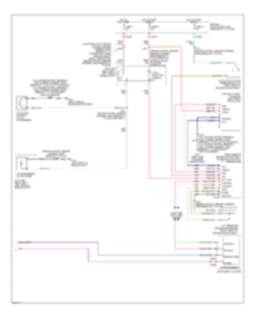
Manual A/C Wiring Diagram (2 of 2) for Ford Pickup F150 2007
 https://portal-diagnostov.com/license.html
Automotive Electricians Portal FZCO
Automotive Electricians Portal FZCO
https://portal-diagnostov.com/license.html
https://portal-diagnostov.com/license.html
Automotive Electricians Portal FZCO
Automotive Electricians Portal FZCOList of elements for Manual A/C Wiring Diagram (2 of 2) for Ford Pickup F150 2007:
- (4.6l: engine control sensor & fuel charge harness, near breakout to a/c clutch solenoid) (5.4l: engine control sensor & fuel charge harness, near breakout to crankshaft position sensor) s122
- (engine control sensor harness, near breakout to g102)
- (engine control sensor harness, near breakout to g110) s116
- (late production: engine control sensor harness, near breakout to integrated wheel ends solenoid) (early production: engine control sensor harness, near breakout to g102)
- (right rear of engine compartment) powertrain control module (pcm)
- (top right front of engine) electronic fan clutch
- A/c pressure transducer sensor (right front of engine compartment)
- A/c clutch cycling pressure switch (right rear of engine compartment)
- A/c clutch relay
- A/c clutch solenoid (on a/c compressor)
- A/c compressor clutch diode
- Ac req
- Acpt
- Auxiliary relay box 1 (left side of engine compt)
- Breakout to a/c clutch solenoid) (5.4l: engine control sensor & fuel charge harness, near breakout to crankshaft position sensor)
- Bvref
- C175b
- C220a
- C220b
- C270a
- C270b
- Can bus +
- Can bus -
- Central junction box (cjb) (near right "a" pillar)
- Computer data lines system
- Defrost req
- Fc-v
- Fss
- Fss-gnd
- Fuse 11 10a
- Fuse 14 10a
- Fuse 32 15a
- G104 (right side of engine compartment)
- G110 (left front of engine compt)
- Hot at all times
- Hot in start or run
- Instrument cluster
- Microprocessor
- Rly ctrl
- S101 (engine control sensor harness, near breakout to auxiliary box 1)
- S104 (engine control sensor harness, near breakout to c139)
- S105
- S107
- S112
- Sig
- Sig_rtn
- Vbpwr
- Vpwr

 Čeština
 Dansk
Dansk Deutsch
 Ελληνικά
 English
 English
 Español
 Suomi
Suomi Français
 Français
 עברית
עברית Hrvatski
 Magyar
 Italiano
 한국어
한국어 Nederlands
 Polski
 Português
 Português
 Română
 Русский
 Slovenčina
 Slovenščina
 Svenska
 Türkçe
 中文 (中国)
