AIR CONDITIONING
3.1L
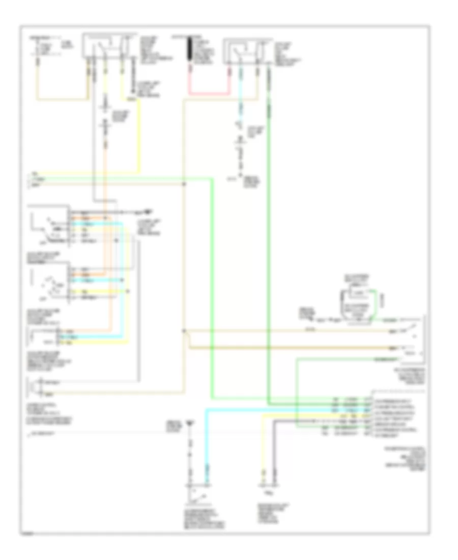
3.1L (VIN D), A/C Wiring Diagram (1 of 2) for Oldsmobile Silhouette 1995
 https://portal-diagnostov.com/license.html
Automotive Electricians Portal FZCO
Automotive Electricians Portal FZCO
https://portal-diagnostov.com/license.html
https://portal-diagnostov.com/license.html
Automotive Electricians Portal FZCO
Automotive Electricians Portal FZCO
List of elements for 3.1L (VIN D), A/C Wiring Diagram (1 of 2) for Oldsmobile Silhouette 1995:
- (mounted to heater and a/c module assembly)
- A/c compressor high pressure cut-off switch (back of a/c compressor)
- A/c compressor low pressure cut-off switch (back of a/c compressor)
- A/c switch
- B-lv
- Blower motor
- Blower motor relay, high speed
- Blower motor relay, low speed (in convenience center)
- Blower motor resistor (mounted to heater and a/c module assembly)
- Blower switch
- Defrost
- Fuse block
- G202 (lower left "a" pillar, left of park brake)
- Heater and a/c control assembly
- Hot at all times
- Hot in run
- Htr-a/c fuse 25a
- Ign fuse 15a
- Interior lights system
- Lower
- Mix(defog)
- Nca
- Off
- Rdo1/aux fuse 20a
- Rear defogger indicator
- Rear defogger switch
- Rear defogger system
- Recirc
- Red
- Solenoid 1
- Solenoid 2
- Solenoid 3
- Solenoid 4
- Solenoid 5
- Solenoid box (below i/p, on right side of heater and a/c module assembly)
- Solid state
- Tan
- Temperature door actuator (top right side of heater and a/c module assembly)
- Upper
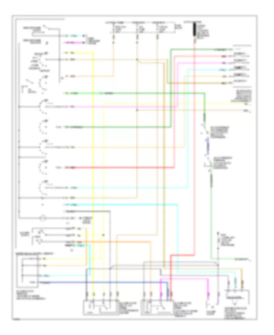
3.1L (VIN D), A/C Wiring Diagram (2 of 2) for Oldsmobile Silhouette 1995
 https://portal-diagnostov.com/license.html
Automotive Electricians Portal FZCO
Automotive Electricians Portal FZCO
https://portal-diagnostov.com/license.html
https://portal-diagnostov.com/license.html
Automotive Electricians Portal FZCO
Automotive Electricians Portal FZCOList of elements for 3.1L (VIN D), A/C Wiring Diagram (2 of 2) for Oldsmobile Silhouette 1995:
- (behind starter motor)
- (in engine compartment, on right inner fender)
- (lower left "a" pillar, left of park brake)
- A/c compres- sor clutch
- A/c compressor clutch relay (behind right headlamp)
- A/c pressure switch
- A/c refrigerant pressure switch (right side of engine compartment, below accumulator)
- A/c request
- Auxiliary blower motor
- Auxiliary blower motor relay (below i/p, left of steering column)
- Auxiliary blower motor resistor (below heater module assembly, on floor duct outlet)
- Auxiliary blower switch (front mounted)
- Auxiliary blower switch (rear mounted) (w/ rear a/c only)
- C10
- Coil
- Compressor control
- Compressor input
- Coolant puller fan
- Coolant puller fan relay (behind right headlamp)
- Coolant temp input
- Diode
- Engine coolant temperature sensor (rear top of engine)
- Fuse block
- G112
- G202
- Hot at all times
- Hot in run
- Med
- Nca
- Off
- Powertrain control module (below right side of i/p, behind convenience center)
- Pusher fan control
- R blw fuse 25a
- Red
- Rr ctrl
- Sensor ground
- Water control solenoid (w/ rear a/c only)
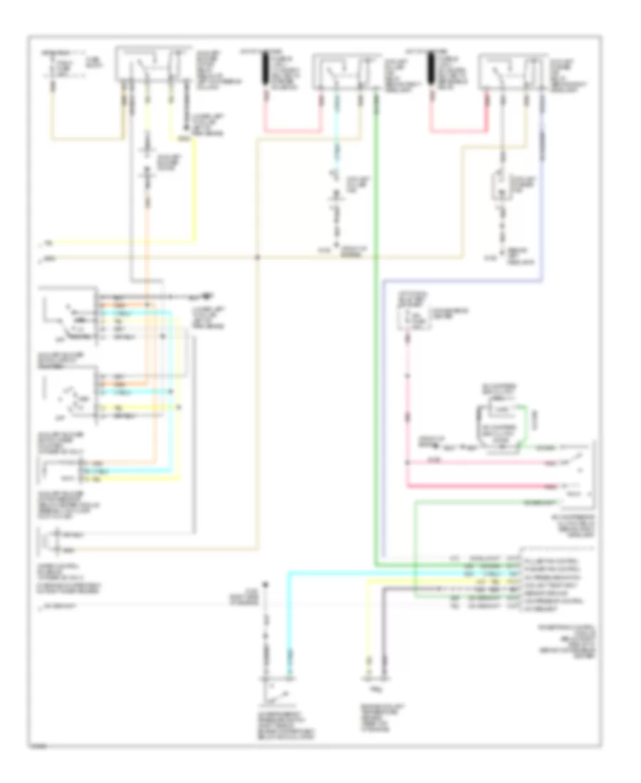
Heater Wiring Diagram for Oldsmobile Silhouette 1995
 https://portal-diagnostov.com/license.html
Automotive Electricians Portal FZCO
Automotive Electricians Portal FZCO
https://portal-diagnostov.com/license.html
https://portal-diagnostov.com/license.html
Automotive Electricians Portal FZCO
Automotive Electricians Portal FZCOList of elements for Heater Wiring Diagram for Oldsmobile Silhouette 1995:
- (lower left "a" pillar, left of park brake)
- (mounted to heater and a/c module assembly)
- (not used)
- Auxiliary blower motor
- Auxiliary blower motor relay (below i/p, left of steering column)
- Auxiliary blower motor resistor (below heater module assembly, on floor duct outlet)
- Auxiliary blower switch (front mounted)
- B-lv
- Blower motor
- Blower motor relay, high speed
- Blower motor relay, low speed (in convenience center)
- Blower motor resistor (mounted to heater and a/c module assembly)
- Blower switch
- C 1995 vftc
- Defrost
- Fuse block
- G202
- G202 (lower left "a" pillar, left of park brake)
- Heater and a/c control assembly
- Hot at all times
- Hot in run
- Htr-a/c fuse 25a
- Ign fuse 15a
- Interior lights system
- Lower
- Med
- Mix(defog)
- Nca
- Not used
- Off
- R blw fuse 25a
- Rdo1/aux fuse 20a
- Rear defogger indicator
- Rear defogger switch
- Rear defogger system
- Red
- Solenoid 1
- Solenoid 2
- Solenoid 3
- Solenoid 5
- Solenoid box (below i/p, on right side of heater and a/c module assembly)
- Solid state
- Tan
- Temperature door actuator (top right side of heater and a/c module assembly)
- Upper
3.8L
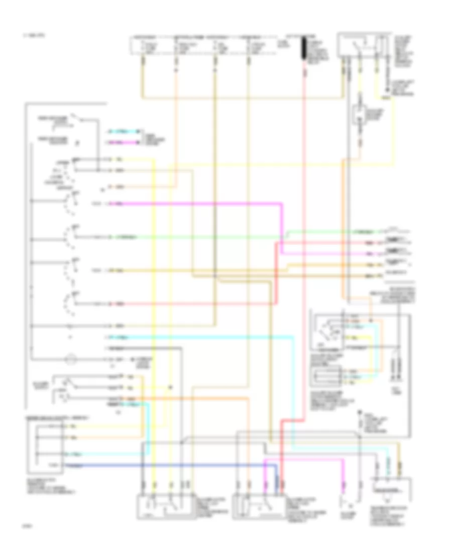
3.8L (VIN L), A/C Wiring Diagram (1 of 2) for Oldsmobile Silhouette 1995
 https://portal-diagnostov.com/license.html
Automotive Electricians Portal FZCO
Automotive Electricians Portal FZCO
https://portal-diagnostov.com/license.html
https://portal-diagnostov.com/license.html
Automotive Electricians Portal FZCO
Automotive Electricians Portal FZCOList of elements for 3.8L (VIN L), A/C Wiring Diagram (1 of 2) for Oldsmobile Silhouette 1995:
- (mounted to heater and a/c module assembly)
- A/c compressor high pressure cut-off switch (back of a/c compressor)
- A/c compressor pressure cycling switch (on side of evaporator)
- A/c switch
- B-lv
- Blower motor
- Blower motor relay, high speed
- Blower motor relay, low speed (in convenience center)
- Blower motor resistor (mounted to heater and a/c module assembly)
- Blower switch
- Defrost
- Fuse block
- G202 (lower left "a" pillar, left of park brake)
- Heater and a/c control assembly
- Hot at all times
- Hot in run
- Htr-a/c fuse 25a
- Ign fuse 15a
- Interior lights system
- Lower
- Mix(defog)
- Nca
- Off
- Rdo1/aux fuse 20a
- Rear defogger indicator
- Rear defogger switch
- Rear defogger system
- Recirc
- Red
- Solenoid 1
- Solenoid 2
- Solenoid 3
- Solenoid 4
- Solenoid 5
- Solenoid box (below i/p, on right side of heater and a/c module assembly)
- Solid state
- Tan
- Temperature door actuator (top right side of heater and a/c module assembly)
- Upper
3.8L (VIN L), A/C Wiring Diagram (2 of 2) for Oldsmobile Silhouette 1995
 https://portal-diagnostov.com/license.html
Automotive Electricians Portal FZCO
Automotive Electricians Portal FZCO
https://portal-diagnostov.com/license.html
https://portal-diagnostov.com/license.html
Automotive Electricians Portal FZCO
Automotive Electricians Portal FZCOList of elements for 3.8L (VIN L), A/C Wiring Diagram (2 of 2) for Oldsmobile Silhouette 1995:
- (behind left headlamp)
- (front of engine)
- (in engine compartment, on right inner fender)
- (lower left "a" pillar, left of park brake)
- A/c compres- sor clutch
- A/c compressor clutch relay (behind right headlamp)
- A/c pressure switch
- A/c refrigerant pressure switch (right side of engine compartment, below accumulator)
- A/c request
- Auxiliary blower motor
- Auxiliary blower motor relay (below i/p, left of steering column)
- Auxiliary blower motor resistor (below heater module assembly, on floor duct outlet)
- Auxiliary blower switch (front mounted)
- Auxiliary blower switch (rear mounted) (w/ rear a/c only)
- C16
- Coil
- Compressor control
- Convenience center
- Coolant puller fan
- Coolant puller fan relay (behind right headlamp)
- Coolant pusher fan
- Coolant pusher fan relay (behind right headlamp)
- Coolant temp input
- D10
- D11
- D12
- Diode
- Engine coolant temperature sensor (rear top of engine)
- F13
- Fuse block
- G106
- G120 (right side of engine)
- G125
- G202
- Hot at all times
- Hot in run
- Hot in run, bulb test or start
- Ign fuse 15a
- Med
- Nca
- Off
- Pnk
- Powertrain control module (below right side of i/p, behind convenience center)
- Puller fan control
- Pusher fan control
- R blw fuse 25a
- Red
- Rr ctrl
- Sensor ground
- Water control solenoid (w/ rear a/c only)
Heater Wiring Diagram for Oldsmobile Silhouette 1995
 https://portal-diagnostov.com/license.html
Automotive Electricians Portal FZCO
Automotive Electricians Portal FZCO
https://portal-diagnostov.com/license.html
https://portal-diagnostov.com/license.html
Automotive Electricians Portal FZCO
Automotive Electricians Portal FZCOList of elements for Heater Wiring Diagram for Oldsmobile Silhouette 1995:
- (lower left "a" pillar, left of park brake)
- (mounted to heater and a/c module assembly)
- (not used)
- Auxiliary blower motor
- Auxiliary blower motor relay (below i/p, left of steering column)
- Auxiliary blower motor resistor (below heater module assembly, on floor duct outlet)
- Auxiliary blower switch (front mounted)
- B-lv
- Blower motor
- Blower motor relay, high speed
- Blower motor relay, low speed (in convenience center)
- Blower motor resistor (mounted to heater and a/c module assembly)
- Blower switch
- C 1995 vftc
- Defrost
- Fuse block
- G202
- G202 (lower left "a" pillar, left of park brake)
- Heater and a/c control assembly
- Hot at all times
- Hot in run
- Htr-a/c fuse 25a
- Ign fuse 15a
- Interior lights system
- Lower
- Med
- Mix(defog)
- Nca
- Not used
- Off
- R blw fuse 25a
- Rdo1/aux fuse 20a
- Rear defogger indicator
- Rear defogger switch
- Rear defogger system
- Red
- Solenoid 1
- Solenoid 2
- Solenoid 3
- Solenoid 5
- Solenoid box (below i/p, on right side of heater and a/c module assembly)
- Solid state
- Tan
- Temperature door actuator (top right side of heater and a/c module assembly)
- Upper

 Čeština
 Dansk
Dansk Deutsch
 Ελληνικά
 English
 English
 Español
 Suomi
Suomi Français
 Français
 עברית
עברית Hrvatski
 Magyar
 Italiano
 한국어
한국어 Nederlands
 Polski
 Português
 Português
 Română
 Русский
 Slovenčina
 Slovenščina
 Svenska
 Türkçe
 中文 (中国)
