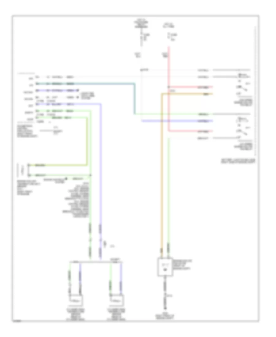
COOLING FAN
Cooling Fan Wiring Diagram for Ford Mustang 2011
 https://portal-diagnostov.com/license.html
Automotive Electricians Portal FZCO
Automotive Electricians Portal FZCO
https://portal-diagnostov.com/license.html
https://portal-diagnostov.com/license.html
Automotive Electricians Portal FZCO
Automotive Electricians Portal FZCO
List of elements for Cooling Fan Wiring Diagram for Ford Mustang 2011:
- 3.7l
- 5.4l
- Accr
- Battery junction box (bjb) (right side of engine compt)
- C1026
- C1381b
- C1381e
- C175b
- C175e
- Cec01
- Cec02
- Cht
- Computer data lines system
- Cylinder head temperature sensor (rear of cylinder head)
- Engine controls system
- Engine coolant temperature (ect) sensor (5.4l) (right front of engine)
- Engine cooling fan motor (front of engine compt)
- Except 3.7l
- Except 5.4l
- Fuse 40a
- Fuse 5a
- G100 (right front of engine compt)
- Hfc
- High speed engine cooling fan relay
- Hot at all times
- Hot w/ pcm power relay energized
- Hs can+
- Hs can-
- Lfc
- Low speed engine cooling fan relay
- Nca
- Powertrain control module (pcm) (right front of engine compt)
- Re141
- Re405
- S102 (5.0l & 5.4l) (5.0l: engine control sensor & fuel charge harness, near breakout to c1019) (5.4l: engine control sensor & fuel charge harness, near breakout to ignition transformer capacitor 1)
- S112
- S121
- S125
- Sigrtn
- Vdb04
- Vdb05
- Ve712
 Čeština
 Dansk
Dansk Deutsch
 Ελληνικά
 English
 English
 Español
 Suomi
Suomi Français
 Français
 עברית
עברית Hrvatski
 Magyar
 Italiano
 한국어
한국어 Nederlands
 Polski
 Português
 Português
 Română
 Русский
 Slovenčina
 Slovenščina
 Svenska
 Türkçe
 中文 (中国)
 日本語
日本語
