ENGINE PERFORMANCE
4.9L
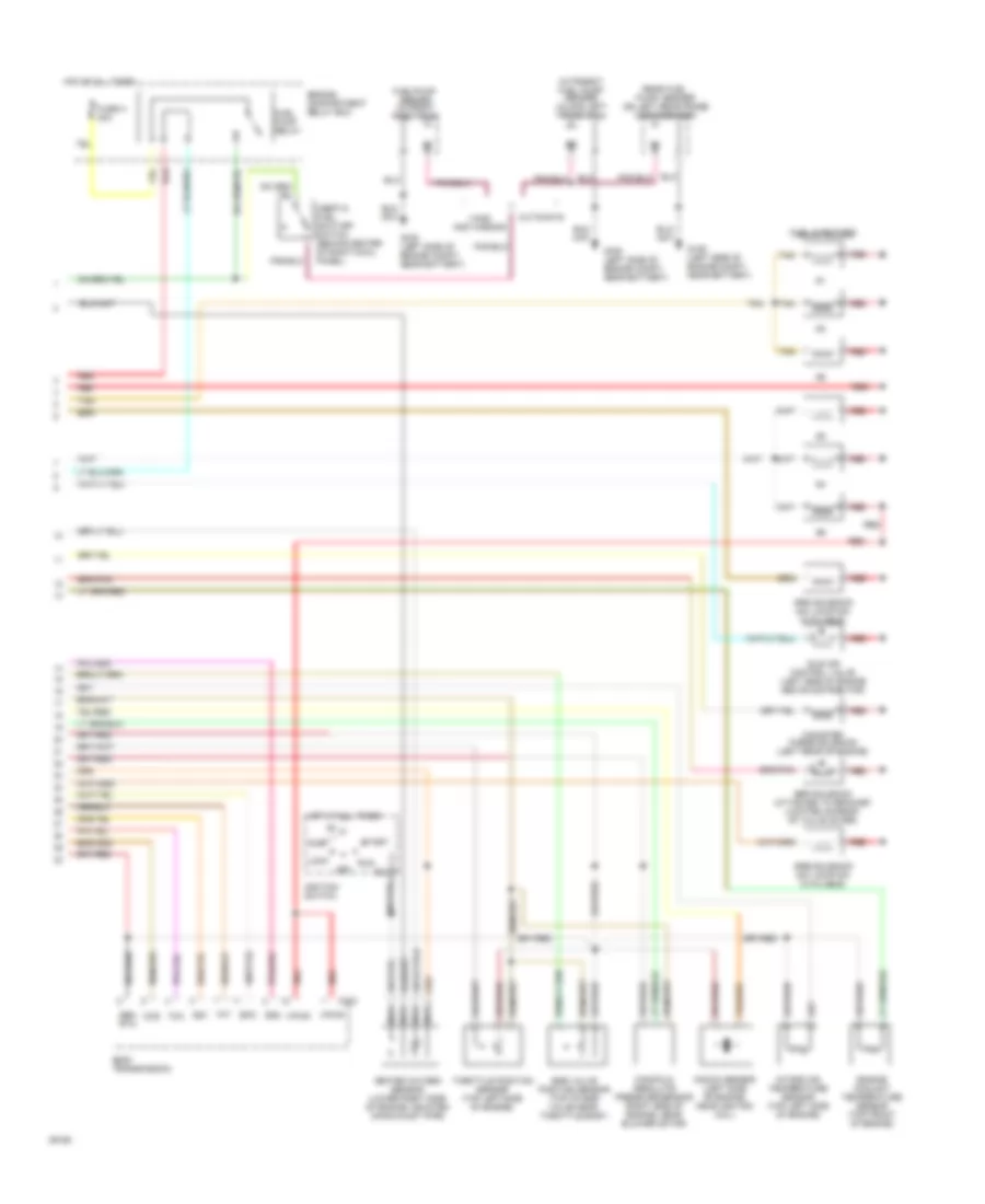
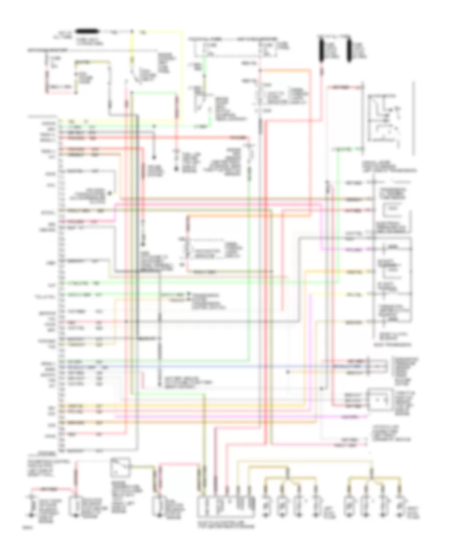
4.9L, Engine Performance Wiring Diagrams (1 of 2) for Ford Econoline E250 1994
 https://portal-diagnostov.com/license.html
Automotive Electricians Portal FZCO
Automotive Electricians Portal FZCO
https://portal-diagnostov.com/license.html
https://portal-diagnostov.com/license.html
Automotive Electricians Portal FZCO
Automotive Electricians Portal FZCO
List of elements for 4.9L, Engine Performance Wiring Diagrams (1 of 2) for Ford Econoline E250 1994:
- 13b
- Accs
- Acd
- Air conditioning system
- Airb
- Aird
- Boo
- Brake on/off switch (behind steering column)
- C162
- C198
- C233
- C317
- Canp
- Ccs
- Coil
- Coil wire
- Cse gnd
- Data (+)
- Data (-)
- Data link connector (left side of engine compt)
- Diode
- Distributor
- Ect
- Engine compartment fuse panel
- Epc
- Epcpwr/vpwr
- Evp
- Evr
- Fpm
- Fuse 1 15a
- Fuse 18 15a
- Fuse c 30a
- Fuse u 30a
- G106 (near battery)
- G206 (attached to i/p, behind cluster)
- Gnd
- Ho2s
- Ho2s gnd
- Hot at all times
- Hot in start or run
- Iac
- Iat
- Idm
- Ign gnd
- Ignition coil (left front of engine)
- Ignition control module (left rear of engine compartment, attached to rear of dash panel)
- Inj bank 1
- Inj bank 2
- Instrument cluster
- Interior fuse panel
- Kapwr
- Malfunction indicator
- Manual lever position sensor
- Map
- Mlp or pnp
- Nca
- Pcm power relay
- Pip
- Pnk
- Powertrain control module (left side of brake master cylinder)
- Psom (+)
- Psom (-)
- Pwr
- Pwr gnd
- Radio capacitor (attached to ignition coil)
- Red
- Shorting bar (left rear of engine compartment)
- Sig rtn
- Speed control servo amplifier assembly (near brake master cylinder)
- Spout
- Ss1
- Ss2
- Sti
- Sto/mil
- Tan
- Tcc
- Tcil
- Tcs
- Tft
- Transmissions system
- Vehicle speed input
- Vpwr
- Vref
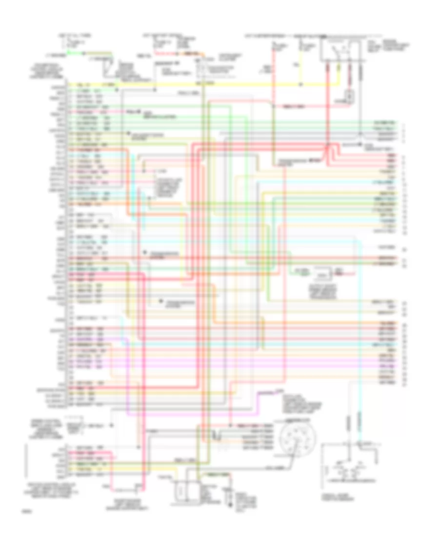
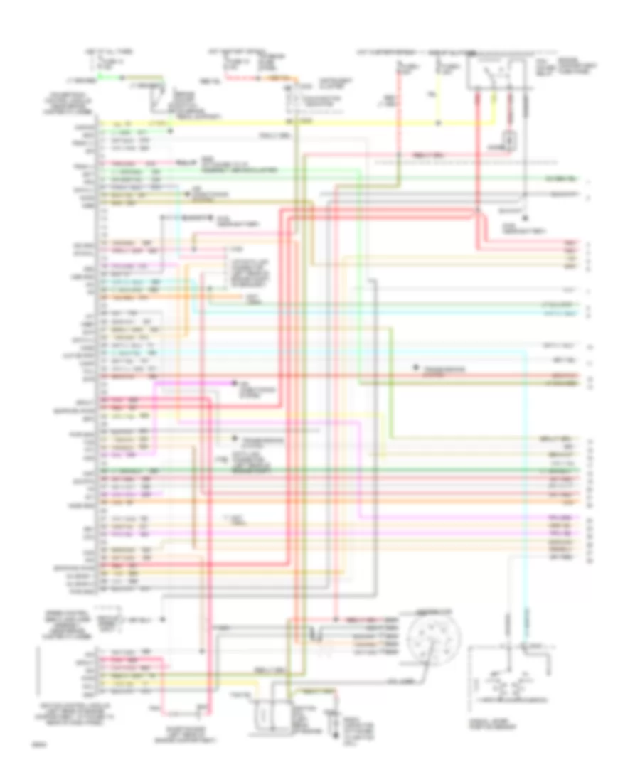
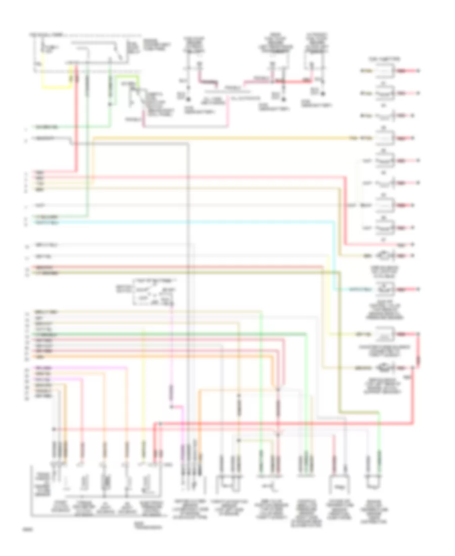
4.9L, Engine Performance Wiring Diagrams (2 of 2) for Ford Econoline E250 1994
 https://portal-diagnostov.com/license.html
Automotive Electricians Portal FZCO
Automotive Electricians Portal FZCO
https://portal-diagnostov.com/license.html
https://portal-diagnostov.com/license.html
Automotive Electricians Portal FZCO
Automotive Electricians Portal FZCOList of elements for 4.9L, Engine Performance Wiring Diagrams (2 of 2) for Ford Econoline E250 1994:
- Acc
- Airb solenoid (no location available)
- Aird solenoid (no location available)
- C303
- Canister purge solenoid (left rear of engine)
- Ccs
- Cutaways
- E40d transmission
- Egr solenoid (attached to bracket located on rear of valve cover)
- Egr valve position sensor (top of egr valve near throttle body)
- Engine compartment relay box
- Engine coolant temperature sensor (top front of engine)
- Epc
- Fuel injectors
- Fuel pump relay
- Fuel/pump sender (in front fuel tank)
- Fuse h 30a
- G106 (left side of engine compt, near battery)
- Heated oxygen sensor (lower right side of engine, mounted on exhaust pipe)
- Hot at all times
- Idle air control valve (left side of engine above distributor)
- Ignition switch
- In-transit fuel pump/ sender (along left frame rail)
- Inertia fuel shut-off switch (behind center of right cowl panel)
- Intake air temperature sensor (top left side of engine)
- Knock sensor (left side of engine, near ignition coil)
- Lock
- Manifold absolute pressure sensor (right side of engine, near blower motor)
- Nca
- Off
- Rear fuel pump/ sender (on left rear frame crossmember)
- Red
- Run
- Sen rtn
- Ss1
- Ss2
- Start
- Tan
- Tcc
- Tft
- Throttle position sensor (top left side of engine)
- Vans and wagons
- Vpwr
5.0L
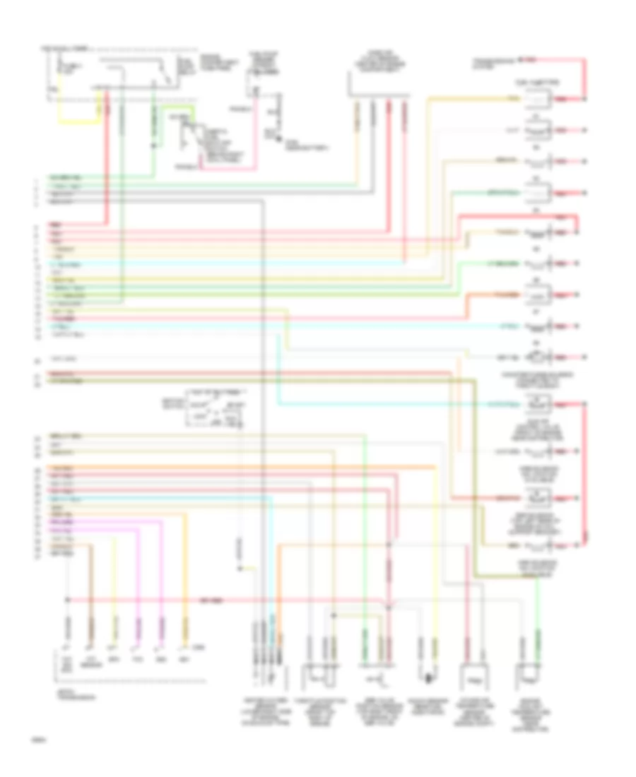
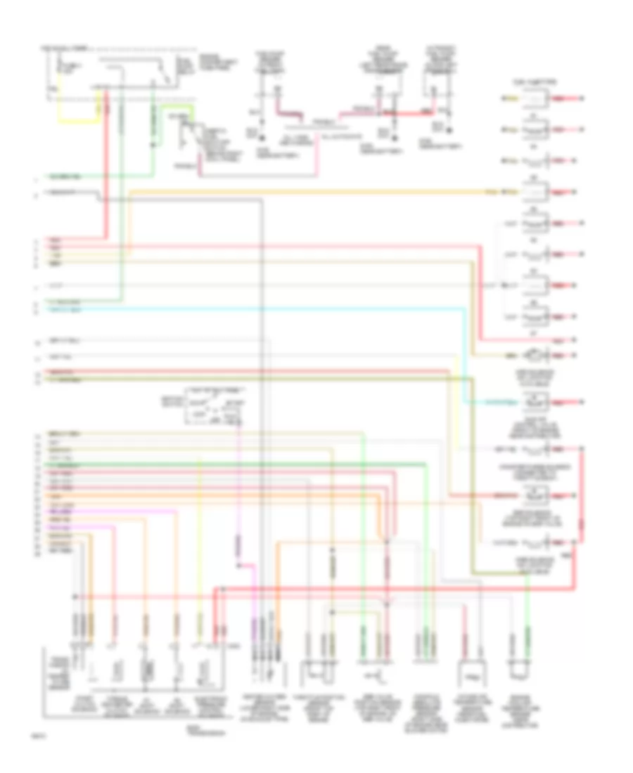
5.0L, Engine Performance Wiring Diagrams (1 of 2) for Ford Econoline E250 1994
 https://portal-diagnostov.com/license.html
Automotive Electricians Portal FZCO
Automotive Electricians Portal FZCO
https://portal-diagnostov.com/license.html
https://portal-diagnostov.com/license.html
Automotive Electricians Portal FZCO
Automotive Electricians Portal FZCOList of elements for 5.0L, Engine Performance Wiring Diagrams (1 of 2) for Ford Econoline E250 1994:
- 13b
- Accs
- Air conditioning system
- Airb
- Aird
- Boo
- Brake on/off switch (on brake pedal support)
- C162
- C163
- C233
- C317
- Coil
- Coil wire
- Cse gnd
- Data (+)
- Data (-)
- Data link connector (left side of engine compartment near park/turn lamp)
- Diode
- Distributor
- Ect
- Engine compartment fuse panel
- Epc
- Epcpwr/vpwr
- Evp
- Evr
- Fpm
- Fuse 13 15a
- Fuse 18 15a
- Fuse c 30a
- Fuse u 30a
- G106 (near battery)
- G206 (behind cluster)
- Gnd
- Ho2s
- Hot at all times
- Hot in start or run
- Iac
- Iat
- Idm
- Ign gnd
- Ignition coil (left rear of engine)
- Ignition control module (left rear of engine compartment, attached to rear of dash panel)
- Inj 3
- Inj 4
- Inj 5
- Inj 6
- Inj 7
- Inj 8
- Inj bank 1
- Inj bank 2
- Instrument cluster
- Interior fuse panel
- Kapwr
- Maf
- Maf rtn
- Malfunction indicator
- Manual lever position sensor
- Mlp
- Nca
- Oss
- Output shaft speed sensor (left rear of transmission)
- Pcm power relay
- Pip
- Pnk
- Powertrain control module (near brake master cylinder)
- Psom (+)
- Psom (-)
- Pwr
- Pwr gnd
- Radio capacitor (attached to ignition coil)
- Red
- Shorting bar (left rear of engine compartment)
- Sig rtn
- Speed control servo amplifier assembly (near brake master cylinder)
- Spout
- Ss1
- Ss2
- Sti
- Sto/mil
- Tan
- Tan/red
- Tcc
- Tcil
- Tcs
- Tft
- Transmissions system
- Vehicle speed input
- Vip data link connector (left front corner of vehicle)
- Vpwr
- Vref
5.0L, Engine Performance Wiring Diagrams (2 of 2) for Ford Econoline E250 1994
 https://portal-diagnostov.com/license.html
Automotive Electricians Portal FZCO
Automotive Electricians Portal FZCO
https://portal-diagnostov.com/license.html
https://portal-diagnostov.com/license.html
Automotive Electricians Portal FZCO
Automotive Electricians Portal FZCOList of elements for 5.0L, Engine Performance Wiring Diagrams (2 of 2) for Ford Econoline E250 1994:
- 4r70w transmission
- Acc
- Airb soleniod (no location available)
- Aird soleniod (no location available)
- C356
- Canister purge solenoid (connected to throttle body)
- Egr solenoid (top left rear of engine on coil support bracket)
- Egr valve position sensor (top right front of engine, on egr valve)
- Engine compartment fuse panel
- Engine coolant temperature sensor (near distributor)
- Epc
- Fuel injectors
- Fuel pump relay
- Fuel/pump sender (in front fuel tank)
- Fuse h 30a
- G106 (near battery)
- Heated oxygen sensor (lower right side of engine, on exhaust pipe)
- Hot at all times
- Idle air control valve (front of engine near distributor)
- Ignition switch
- Inertia fuel shut-off switch (behind right cowl panel)
- Intake air temperature sensor (center of engine compt)
- Knock sensor (near fuel injector #4)
- Lock
- Mass air flow sensor (center of engine compartment)
- Nca
- Off
- Red
- Run
- Ss1
- Ss2
- Start
- Tan
- Tan/red
- Tcc
- Tft sensor
- Throttle position sensor (front top right of engine)
- Tot sig rtn
- Transmissions system
5.8L
5.8L, Engine Performance Wiring Diagrams (1 of 2) for Ford Econoline E250 1994
 https://portal-diagnostov.com/license.html
Automotive Electricians Portal FZCO
Automotive Electricians Portal FZCO
https://portal-diagnostov.com/license.html
https://portal-diagnostov.com/license.html
Automotive Electricians Portal FZCO
Automotive Electricians Portal FZCOList of elements for 5.8L, Engine Performance Wiring Diagrams (1 of 2) for Ford Econoline E250 1994:
- (not used)
- 13b
- Accs
- Acd
- Air conditioning system
- Airb
- Aird
- Boo
- Brake on/off switch (on brake pedal support)
- C162
- C163
- C233
- C317
- Canp
- Ccc
- Ccs
- Coil
- Coil wire
- Cse gnd
- Data (+)
- Data (-)
- Data link connector (left rear of engine compt)
- Diode
- Distributor
- Ecppwr/vpwr
- Ect
- Engine compartment fuse panel
- Epc
- Epcpwr/vpwr
- Evp
- Evr
- Fpm
- Fuse 13 15a
- Fuse 18 15a
- Fuse c 30a
- Fuse u 30a
- G106 (near battery)
- G206 (attached to i/p assembly, behind cluster)
- Gnd
- Ho2s
- Ho2s gnd
- Hot at all times
- Hot in start or run
- Iac
- Iat
- Idm
- Ign gnd
- Ignition coil (left rear of engine)
- Ignition control module (left rear of engine compartment, attached to rear of dash panel)
- Inj bank 1
- Inj bank 2
- Instrument cluster
- Interior fuse panel
- Kapwr
- Malfunction indicator
- Manual lever position sensor
- Map
- Mlp or pnp
- Nca
- Pcm power relay
- Pip
- Pnk
- Powertrain control module (near brake master cylinder)
- Psom (+)
- Psom (-)
- Pwr
- Pwr gnd
- Radio capacitor (attached to ignition coil)
- Red
- Shorting bar (left rear of engine compartment)
- Sig rtn
- Speed control servo amplifier assembly (near brake master cylinder)
- Spout
- Ss1
- Ss2
- Sti
- Sto/mil
- Tan
- Tcil
- Tcs
- Tft
- Transmissions system
- Vehicle speed input
- Vip data link connector (left rear of engine compt, on bracket)
- Vref
5.8L, Engine Performance Wiring Diagrams (2 of 2) for Ford Econoline E250 1994
 https://portal-diagnostov.com/license.html
Automotive Electricians Portal FZCO
Automotive Electricians Portal FZCO
https://portal-diagnostov.com/license.html
https://portal-diagnostov.com/license.html
Automotive Electricians Portal FZCO
Automotive Electricians Portal FZCOList of elements for 5.8L, Engine Performance Wiring Diagrams (2 of 2) for Ford Econoline E250 1994:
- #1 shift solenoid
- #2 shift solenoid
- Acc
- Airb soleniod (no location available)
- Aird soleniod (no location available)
- All cutaways
- All vans and wagons
- C303
- Canister purge solenoid (connected to throttle body)
- Coast clutch solenoid
- E40d transmission
- Egr solenoid (top right front of engine on egr valve)
- Egr valve position sensor (top right front of engine, on egr valve)
- Electronic pressure control solenoid
- Engine compartment fuse panel
- Engine coolant temperature sensor (near distributor)
- Fuel injectors
- Fuel pump relay
- Fuel/pump sender (in front fuel tank)
- Fuse h 30a
- G106 (near battery)
- Heated oxygen sensor (lower right side of engine, on exhaust pipe)
- Hot at all times
- Idle air control valve (front of engine near distributor)
- Ignition switch
- In-transit fuel pump/ sender (along left frame rail)
- Inertia fuel shut-off switch (behind right cowl panel)
- Intake air temperature sensor (near fuel injector #6)
- Lock
- Manifold absolute pressure sensor (right side of engine near blower motor)
- Nca
- Off
- Rear fuel pump/ sender (left rear frame crossmember)
- Red
- Run
- Start
- Tan
- Throttle position sensor (front top right of engine)
- Torque converter clutch solenoid
- Trans- mission oil temper- ature sensor
7.3L
7.3L Diesel, Engine Performance Wiring Diagrams for Ford Econoline E250 1994
 https://portal-diagnostov.com/license.html
Automotive Electricians Portal FZCO
Automotive Electricians Portal FZCO
https://portal-diagnostov.com/license.html
https://portal-diagnostov.com/license.html
Automotive Electricians Portal FZCO
Automotive Electricians Portal FZCOList of elements for 7.3L Diesel, Engine Performance Wiring Diagrams for Ford Econoline E250 1994:
- "wait to start" indicator
- #1 shift solenoid
- #2 shift solenoid
- (closed
- (front left side of engine)
- (left side of safety wall,
- 13b
- 4x4l
- Accs
- Air condi- tioning system (a/c compressure clutch)
- Baro
- Barometric pressure sensor (baro) (near blower motor)
- Boo
- Brake on/off (boo) switch (on brake pedal support)
- C240
- Ccc
- Ccs
- Coast clutch solenoid
- Cold idle solenoid (top center front of engine)
- Cold timimg advance solenoid (top right side of engine)
- Cruise control system
- Cse gnd
- Diesel warning lamps display
- E4od transmission
- Electronic pressure con- trol solenoid
- Engine compart- ment fuse
- Engine rpm sensor (center front of engine, near throttle position sensor)
- Engine temperature switch below 62 c, 144 f)
- Epc
- Epcpwr
- Fuel line heater (top left side of engine)
- Fuel shutoff solenoid (top of engine)
- Fuse 15a
- Fuse panel
- Fuse u 30a
- G206 (attached to instrument panel assembly, behind cluster)
- Glow plug controller (top center rear of engine)
- Glow plugs
- Hot at all times
- Hot in run or start
- Ign feed
- Kapwr
- Left glow plugs
- Malfunction indicator
- Manual lever position sensor (left side of transmission)
- Mlp
- Nca
- Panel
- Pcm power diode
- Pcm power relay
- Plugs glow
- Powertrain control module (pcm)
- Psom (+)
- Psom (-)
- Pwr gnd
- Red
- Right glow plugs
- Rpms (+)
- Rpms (-)
- Sig rtn
- Ss1
- Ss2
- Sti
- Sto/mil
- Tac
- Tcil & tmil
- Tcs
- Tft
- Throttle position sensor (top left side of engine)
- Torque con- verter clutch solenoid
- Tps
- Transmission oil tempera- ture sensor
- Transmission system (transmission control switch)
- Vip data link connectors (left front corner of vehicle)
- Vpwr
- Vref
- Wait to start
7.5L
7.5L, Engine Performance Wiring Diagrams (1 of 2) for Ford Econoline E250 1994
 https://portal-diagnostov.com/license.html
Automotive Electricians Portal FZCO
Automotive Electricians Portal FZCO
https://portal-diagnostov.com/license.html
https://portal-diagnostov.com/license.html
Automotive Electricians Portal FZCO
Automotive Electricians Portal FZCOList of elements for 7.5L, Engine Performance Wiring Diagrams (1 of 2) for Ford Econoline E250 1994:
- (not used)
- 13b
- Accs
- Acd
- Air conditioning system
- Airb
- Boo
- Brake on/off switch (on brake pedal support)
- C162
- C163
- C233
- C317
- Canp
- Ccc
- Ccs
- Coil
- Coil wire
- Cse gnd
- Data (+)
- Data (-)
- Data link connector (left rear of engine compt)
- Diode
- Distributor
- Ecppwr/vpwr
- Ect
- Engine compartment fuse panel
- Epc
- Epcpwr/vpwr
- Evp
- Evr
- Fpm
- Fuse 13 15a
- Fuse 18 15a
- Fuse c 30a
- Fuse u 30a
- G106 (near battery)
- G206 (attached to i/p assembly, behind cluster)
- Gnd
- Ho2s
- Ho2s gnd
- Hot at all times
- Hot in start or run
- Iac
- Iat
- Idm
- Ign gnd
- Ignition coil (left rear of engine)
- Ignition control module (left rear of engine compartment, attached to rear of dash panel)
- Inj bank 1
- Inj bank 2
- Instrument cluster
- Interior fuse panel
- Kapwr
- Malfunction indicator
- Manual lever position sensor
- Map
- Mlp or pnp
- Nca
- Pcm power relay
- Pip
- Pnk
- Powertrain control module (near brake master cylinder)
- Psom (+)
- Psom (-)
- Pwr
- Pwr gnd
- Radio capacitor (attached to ignition coil)
- Red
- Shorting bar (left rear of engine compartment)
- Sig rtn
- Speed control servo amplifier assembly (near brake master cylinder)
- Spout
- Ss1
- Ss2
- Sti
- Sto/mil
- Tan
- Tcil
- Tcs
- Tft
- Transmissions system
- Vehicle speed input
- Vip data link connector (left rear of engine compt, on bracket)
- Vref
7.5L, Engine Performance Wiring Diagrams (2 of 2) for Ford Econoline E250 1994
 https://portal-diagnostov.com/license.html
Automotive Electricians Portal FZCO
Automotive Electricians Portal FZCO
https://portal-diagnostov.com/license.html
https://portal-diagnostov.com/license.html
Automotive Electricians Portal FZCO
Automotive Electricians Portal FZCOList of elements for 7.5L, Engine Performance Wiring Diagrams (2 of 2) for Ford Econoline E250 1994:
- #1 shift solenoid
- #2 shift solenoid
- Acc
- Airb soleniod (no location available)
- All cutaways
- All vans and wagons
- C303
- Canister purge solenoid (connected to throttle body)
- Coast clutch solenoid
- E40d transmission
- Egr solenoid (top left rear of engine, on coil support bracket)
- Egr valve position sensor (top of egr valve near throttle body)
- Electronic pressure control solenoid
- Engine compartment fuse panel
- Engine coolant temperature sensor (near distributor)
- Fuel injectors
- Fuel pump relay
- Fuel/pump sender (in front fuel tank)
- Fuse h 30a
- G106 (near battery)
- Heated oxygen sensor (lower right side of engine, on exhaust pipe)
- Hot at all times
- Idle air control valve (top rear of engine near oil pressure sender)
- Ignition switch
- In-transit fuel pump/ sender (along left frame rail)
- Inertia fuel shut-off switch (behind right cowl panel)
- Intake air temperature sensor (near fuel injector #6)
- Lock
- Manifold absolute pressure sensor (right side of engine near blower motor)
- Nca
- Off
- Rear fuel pump/ sender (left rear frame crossmember)
- Red
- Run
- Start
- Tan
- Throttle position sensor (top left side of engine)
- Torque converter clutch solenoid
- Trans- mission oil temper- ature sensor

 Čeština
 Dansk
Dansk Deutsch
 Ελληνικά
 English
 English
 Español
 Suomi
Suomi Français
 Français
 עברית
עברית Hrvatski
 Magyar
 Italiano
 한국어
한국어 Nederlands
 Polski
 Português
 Português
 Română
 Русский
 Slovenčina
 Slovenščina
 Svenska
 Türkçe
 中文 (中国)
