ENGINE PERFORMANCE
4.0L
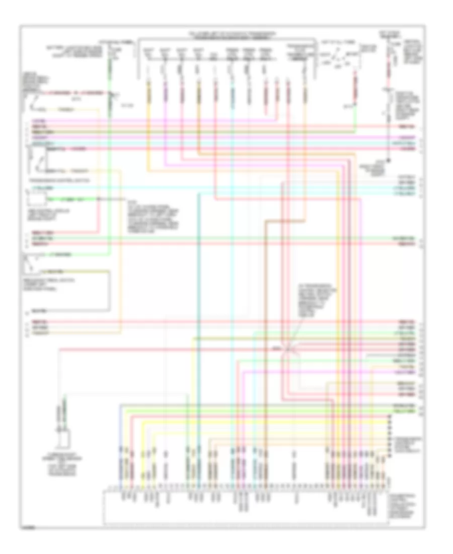
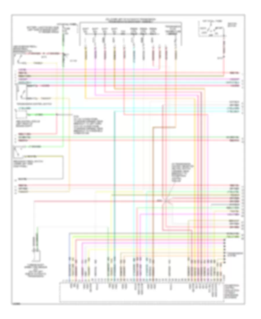
4.0L, Engine Performance Wiring Diagram (1 of 4) for Ford Explorer 2005
 https://portal-diagnostov.com/license.html
Automotive Electricians Portal FZCO
Automotive Electricians Portal FZCO
https://portal-diagnostov.com/license.html
https://portal-diagnostov.com/license.html
Automotive Electricians Portal FZCO
Automotive Electricians Portal FZCO
List of elements for 4.0L, Engine Performance Wiring Diagram (1 of 4) for Ford Explorer 2005:
- (in dash panel to engine harness, near breakout to
- (in dash panel to engine harness, near breakout to a/c clutch cycling pressure switch)
- (in dash panel to engine harness, near breakout to left horn) s168
- (in dash panel to engine harness, near breakout to powertrain control module)
- (in main harness, near breakout to left side of dash)
- A/c clutch cycling pressure switch)
- A/c sw
- Ac demand
- Accelerator pedal position sensor (under left side of dash)
- Air conditioning system
- Anti-theft system
- Audio unit
- Battery junction box (bjb) (left side of engine compt, at fender apron)
- Brake in
- Brake pressure switch (mounted on master cylinder)
- C175b
- C240a
- C290a
- Can bus +
- Can bus -
- Can vent
- Cruise control system
- Data link connector (dlc) (behind left side of dash)
- Dr ajar
- Evap pu
- Evaporative emission (evap) canister vent valve (right rear of vehicle, on frame rail)
- Feps
- Fpm
- Fuse 15a
- Fuse 20a
- Fuse 2a
- Fuse 40a
- G101 (left front of engine compt)
- G103 (right front of engine compt)
- G104 (right rear of (right rear of engine compt) engine compt)
- G105 (right rear of engine compt)
- Ground
- Hot at all times
- Hot in run or start
- Iat in
- Ind ctrl
- Maf out
- Mass airflow (maf) sensor (right front of engine compt, on fender)
- Od off
- Passive anti-theft transceiver (on steering column)
- Pcm power diode
- Pcm power relay
- Pos 1
- Pos 2
- Pos 3
- Powertrain control module (pcm) (at right side engine bulkhead)
- Press sw
- Red
- Red/pnk
- Rtn
- S127
- S130
- S131
- S132
- S148
- S150
- S209
- S212
- Sens rtn
- Sig rtn
- Srs
- St mtr
- Starting/charging system
- Tan
- Tank press
- Transmission system (4wd circuit)
- Tx sig
- Vapor management valve (left rear of engine compt)
- Vbatt
- Vpwr
- Vref
- Vss
- W/ 4x4
- W/ audiophile
- W/o audiophile
- W/o ivd w/ ivd
- Windshield wiper motor (at left rear of engine compt)
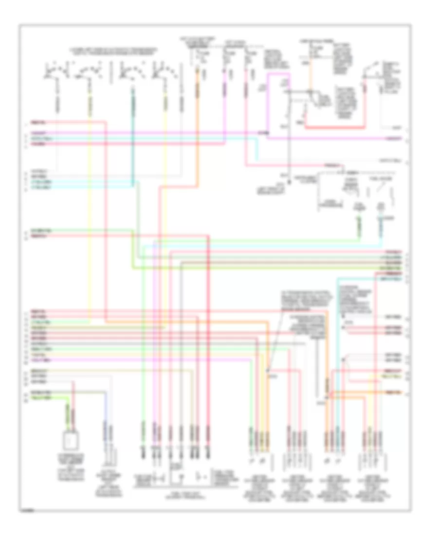
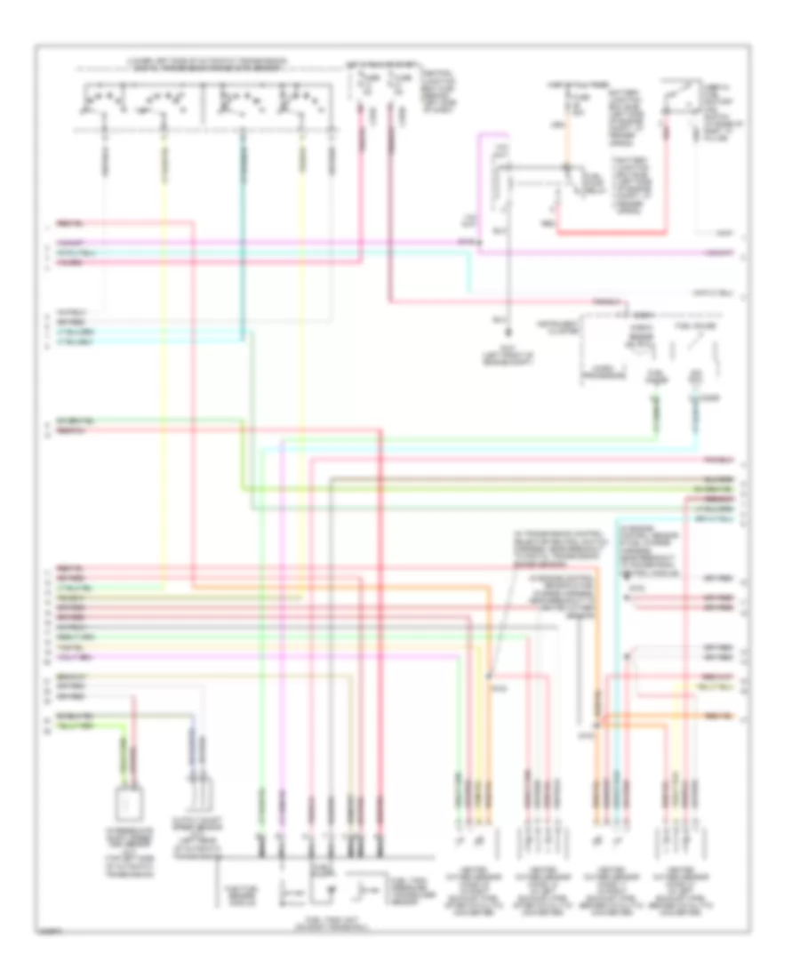
4.0L, Engine Performance Wiring Diagram (2 of 4) for Ford Explorer 2005
 https://portal-diagnostov.com/license.html
Automotive Electricians Portal FZCO
Automotive Electricians Portal FZCO
https://portal-diagnostov.com/license.html
https://portal-diagnostov.com/license.html
Automotive Electricians Portal FZCO
Automotive Electricians Portal FZCOList of elements for 4.0L, Engine Performance Wiring Diagram (2 of 4) for Ford Explorer 2005:
- (above brake pedal) brake pedal position switch
- (in transmission control selector neutral switch harness, near breakout to powertrain control module)
- (on lower left of automatic transmission) transmission solenoid body assembly
- Abs control module (left front of engine compt)
- Acc
- Battery junction box (bjb) (left side of engine compt, at fender apron)
- C175t
- C270c
- Central junction box (cjb) (behind left side of dash)
- Fuse 5a
- G103 (right front of engine compt)
- H2os 12 htr
- H2os 12 in
- H2os 22 htr
- H2os 22 in
- Hot at all times
- Hot in run or start
- Ignition switch
- Iss
- Lock
- Nca
- Off
- Oss
- Pcs a
- Pcs b
- Pcs c
- Positive crankcase ventilation heater (right rear of engine compt)
- Powertrain control module (pcm) (at right side engine bulkhead)
- Press ctrl sol a
- Press ctrl sol b
- Press ctrl sol c
- Red/pnk
- Redundant pedal switch (under left side dash panel)
- S101
- S113
- S120 (w/ ivd: in dash panel to engine harness, near breakout to left horn) (w/o ivd: in dash panel to engine harness, near breakout to windshield wiper motor)
- S173
- Shift sol a
- Shift sol b
- Shift sol c
- Shift sol d
- Sig rtn
- Ss a
- Ss b
- Ss c
- Ss d
- Start
- Tcc sol
- Transmission control switch
- Transmission controls system (4wd circuit)
- Transmission fluid temperature sensor
- Tss
- Turbine shaft speed (tss) sensor (a/t) (top left side of automatic transmission)
- Vref
- W/ ivd
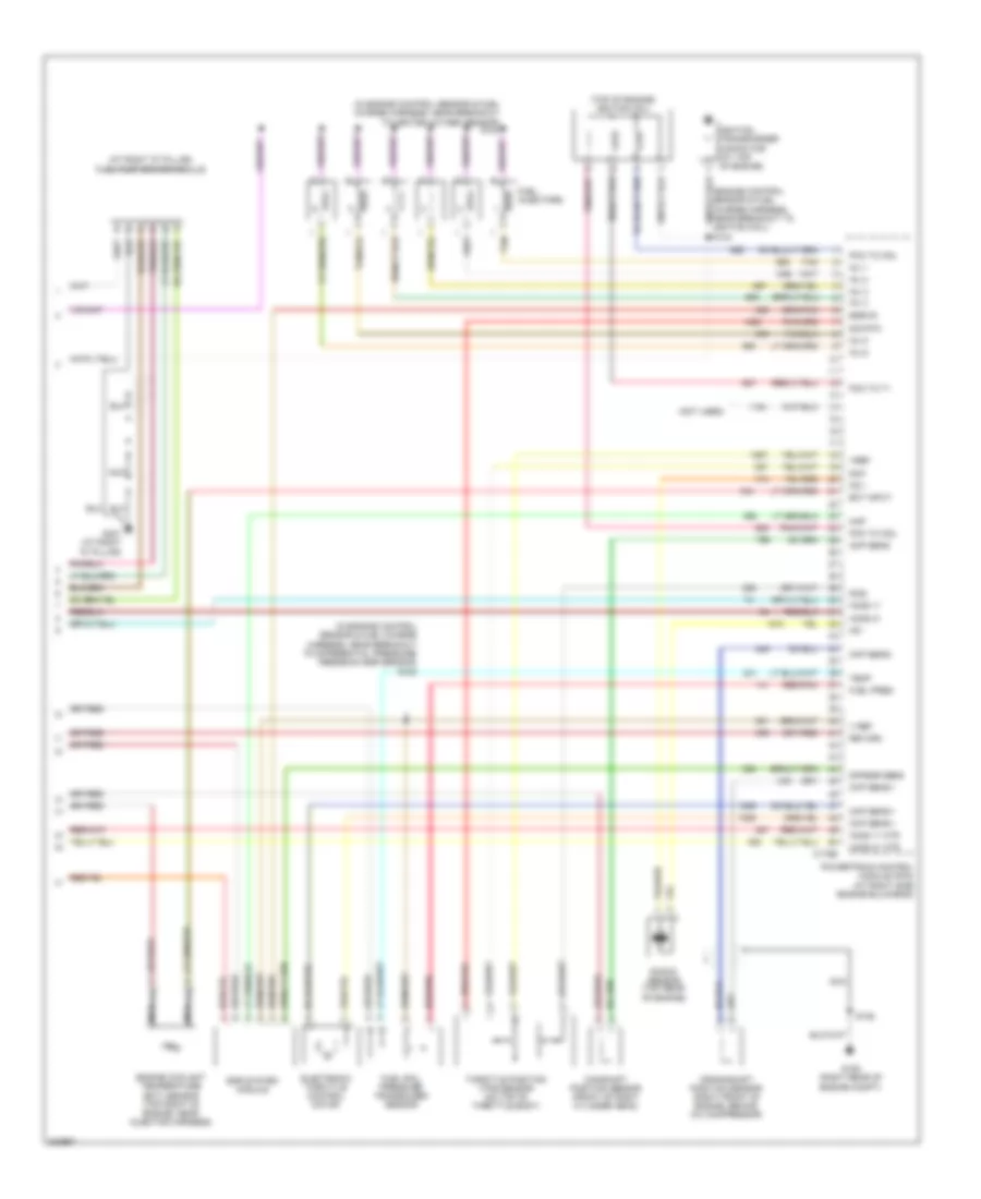
4.0L, Engine Performance Wiring Diagram (3 of 4) for Ford Explorer 2005
 https://portal-diagnostov.com/license.html
Automotive Electricians Portal FZCO
Automotive Electricians Portal FZCO
https://portal-diagnostov.com/license.html
https://portal-diagnostov.com/license.html
Automotive Electricians Portal FZCO
Automotive Electricians Portal FZCOList of elements for 4.0L, Engine Performance Wiring Diagram (3 of 4) for Ford Explorer 2005:
- (in engine control sensor & fuel charge harness, near breakout to powertrain control module)
- (in engine control sensor & fuel charge harness, near breakout to heated oxygen sensor)
- (in transmission control selector neutral switch harness, near breakout to digital transmission range sensor)
- (lower left side of automatic transmission) digital transmission range (dtr) sensor
- Battery junction box (bjb) (left side of engine compt, at fender apron)
- C220a
- C270a
- C270f
- C270h
- Central junction box (cjb) (behind left side of dash)
- Check
- Engine
- Flex fuel sender module
- Fuel gauge
- Fuel pump
- Fuel pump relay
- Fuel tank pressure transducer sensor
- Fuel tank unit (on right frame rail)
- Fuse 10a
- Fuse 20a
- Fuse 5a
- G101 (left front of engine compt)
- Heated oxygen sensor (ho2s) 11 (in right exhaust pipe before catalytic converter)
- Heated oxygen sensor (ho2s) 12 (in left exhaust pipe, after catalytic converter)
- Heated oxygen sensor (ho2s) 21 (in left exhaust pipe, before catalytic converter)
- Heated oxygen sensor (ho2s) 22 (in right exhaust pipe, after catalytic converter)
- Hot at all times
- Hot in run or start
- Hot with battery saver relay energized
- Inertia fuel shutoff (ifs) switch (base of right "a" pillar)
- Instrument cluster
- Intermediate shaft speed (iss) sensor (a/t) (top left side
- Micro- processor
- N r
- Nca
- Of automatic transmission)
- Output shaft speed sensor (a/t) (left rear
- Red
- Red/pnk
- S100
- S102
- S103
- S146
- Sig rtn
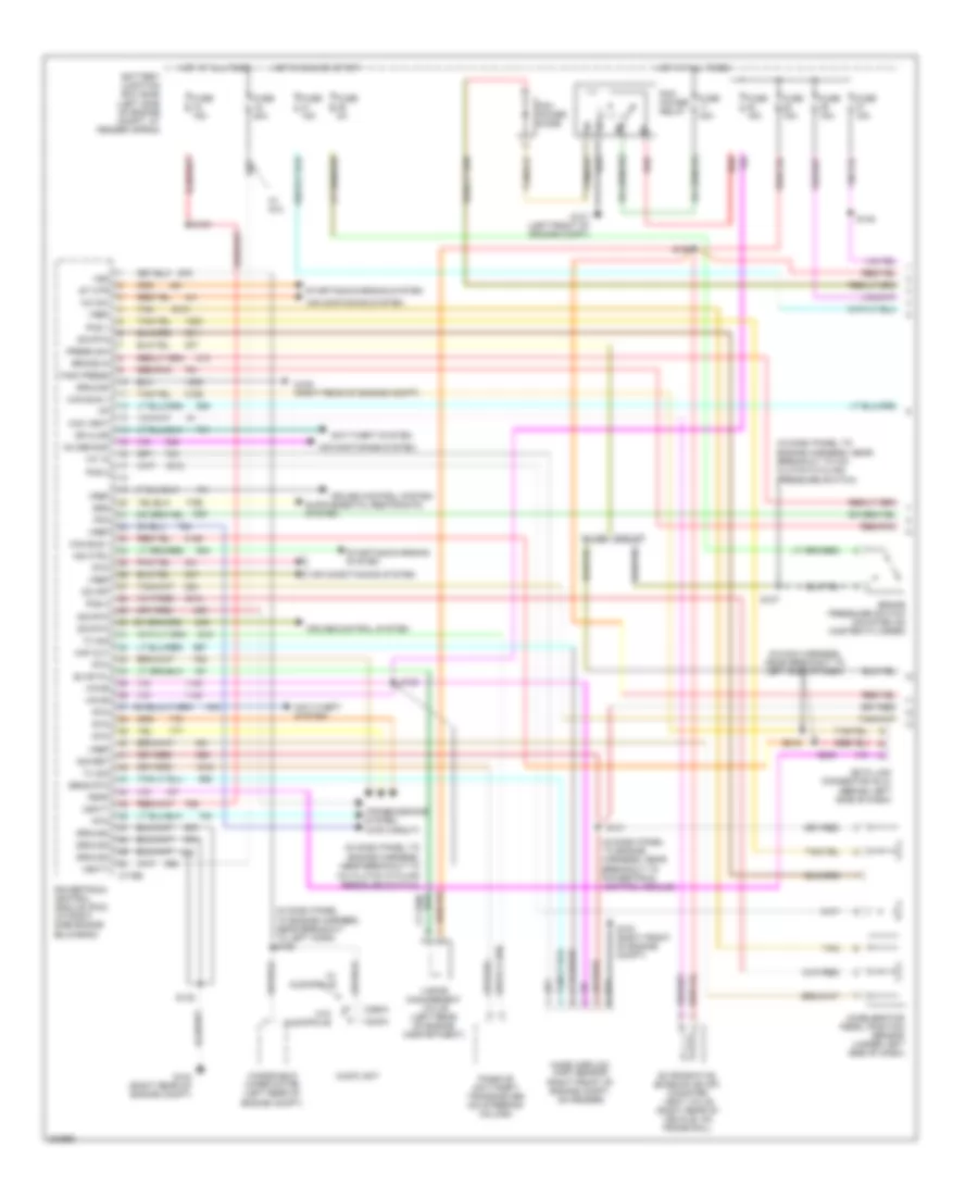
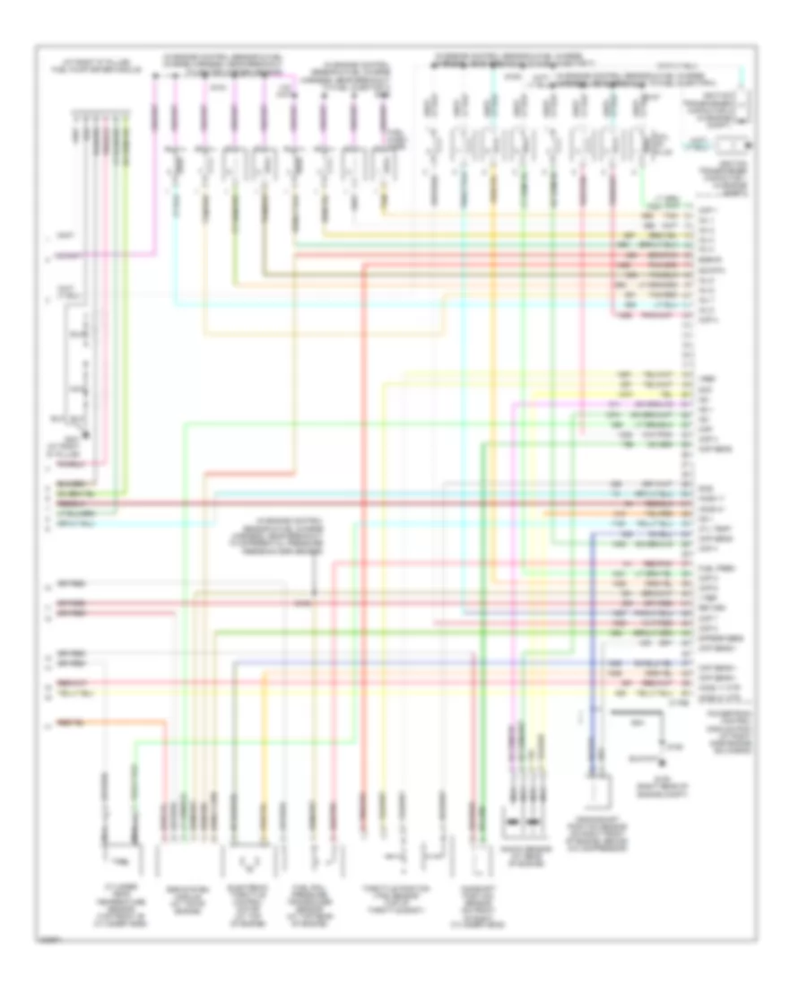
4.0L, Engine Performance Wiring Diagram (4 of 4) for Ford Explorer 2005
 https://portal-diagnostov.com/license.html
Automotive Electricians Portal FZCO
Automotive Electricians Portal FZCO
https://portal-diagnostov.com/license.html
https://portal-diagnostov.com/license.html
Automotive Electricians Portal FZCO
Automotive Electricians Portal FZCOList of elements for 4.0L, Engine Performance Wiring Diagram (4 of 4) for Ford Explorer 2005:
- (at right "d" pillar) fuel pump driver module
- (engine control sensor & fuel charge harness, near breakout to ignition coil) s134
- (in engine control sensor & fuel charge harness, near breakout to differential pressure feedback egr sensor) s105
- (in engine control sensor & fuel charge harness, near breakout to heated oxygen sensor) s104
- (not used)
- (top of engine) ignition coil
- C175e
- Camshaft position sensor (front of right cylinder head)
- Ckp sens +
- Ckp sens -
- Cmp sens
- Crankshaft position sensor (right front of engine, behind a/c compressor)
- Dfpegr sens
- Ect input
- Egr system module
- Egrvr
- Electronic throttle control motor
- Engine coolant temperature (ect) sensor (top right of engine, near injector harness)
- Fuel injectors
- Fuel pres
- Fuel rail pressure transducer sensor
- G105 (right rear of engine compt)
- G401 (at right "d" pillar)
- Ho2s 11
- Ho2s 11 htr
- Ho2s 21
- Ho2s 21 htr
- Ignition transformer capacitor (at top of engine)
- Inj 1
- Inj 2
- Inj 3
- Inj 4
- Inj 5
- Inj 6
- Knock sensor (top rear of engine)
- Ks +
- Ks -
- Map
- Nca
- Pcm to coil
- Pcm to t1
- Powertrain control module (pcm) (at right side engine bulkhead)
- Red/pnk
- Return
- S106
- Sig rtn
- Sig1
- Sig2
- Tan
- Temp
- Throttle position (tps) sensor (on top of throttle body)
- V ref
- Vref
4.6L
4.6L, Engine Performance Wiring Diagram (1 of 4) for Ford Explorer 2005
 https://portal-diagnostov.com/license.html
Automotive Electricians Portal FZCO
Automotive Electricians Portal FZCO
https://portal-diagnostov.com/license.html
https://portal-diagnostov.com/license.html
Automotive Electricians Portal FZCO
Automotive Electricians Portal FZCOList of elements for 4.6L, Engine Performance Wiring Diagram (1 of 4) for Ford Explorer 2005:
- (in dash panel to engine harness, near breakout to
- (in dash panel to engine harness, near breakout to a/c clutch cycling pressure switch)
- (in dash panel to engine harness, near breakout to left horn) s168
- (in dash panel to engine harness, near breakout to powertrain control module)
- (in main harness, near breakout to left side of dash)
- A/c clutch cycling pressure switch)
- A/c sw
- Ac demand
- Accelerator pedal position sensor (under left side of dash)
- Air conditioning system
- Air contioning system
- Anti-theft system
- Audio unit
- Battery junction box (bjb) (left side of engine compt, at fender apron)
- Brake in
- Brake pressure switch (mounted on master cylinder)
- C175b
- C240a
- C290a
- Can bus +
- Can bus -
- Can vent
- Cruise control system
- Data link connector (dlc) (behind left side of dash)
- Dr ajar
- Evap pu
- Evaporative emission (evap) canister vent valve (right rear of vehicle, on frame rail)
- Feps
- Fpm
- Fuse 15a
- Fuse 20a
- Fuse 2a
- Fuse 40a
- G101 (left front of engine compt)
- G103 (right front of engine compt)
- G104 (right rear of engine compt)
- G105 (right rear of engine compt)
- Ground
- Hot at all times
- Hot in run or start
- Iat in
- Ind ctrl
- Maf out
- Mass airflow (maf) sensor (right front of engine compt, on fender)
- Od off
- Passive anti-theft transceiver (on steering column)
- Pcm power diode
- Pcm power relay
- Pos 1
- Pos 2
- Pos 3
- Powertrain control module (pcm) (at right side engine bulkhead)
- Press sw
- Red
- Red/pnk
- Rtn
- S127
- S130
- S131
- S132
- S148
- S149
- S150
- S209
- S212
- Sens rtn
- Sig ret
- Sig rtn
- Srs
- St mtr
- Starting/charging system
- Tan
- Tank press
- Transmissions system (4wd circuit)
- Tx sig
- Vapor management valve (left rear of engine compartment)
- Vbatt
- Vpwr
- Vref
- Vss
- W/ 4x4
- W/ audiophile
- W/o audiophile
- W/o ivd w/ ivd
- Windshield wiper motor (left rear of engine compt)
4.6L, Engine Performance Wiring Diagram (2 of 4) for Ford Explorer 2005
 https://portal-diagnostov.com/license.html
Automotive Electricians Portal FZCO
Automotive Electricians Portal FZCO
https://portal-diagnostov.com/license.html
https://portal-diagnostov.com/license.html
Automotive Electricians Portal FZCO
Automotive Electricians Portal FZCOList of elements for 4.6L, Engine Performance Wiring Diagram (2 of 4) for Ford Explorer 2005:
- (above brake pedal) brake pedal position switch
- (in transmission control selector neutral switch harness, near breakout to powertrain control module)
- (on lower left of automatic transmission) transmission solenoid body assembly
- Abs control module (left front of engine compt)
- Acc
- Battery junction box (bjb) (left side of engine compt, at fender apron)
- C175t
- H2os 12 htr
- H2os 12 in
- H2os 22 htr
- H2os 22 in
- Hot at all times
- Ignition switch
- Iss
- Lock
- Nca
- Off
- Oss
- Pcs a
- Pcs b
- Pcs c
- Powertrain control module (pcm) (at right side engine bulkhead)
- Press ctrl sol a
- Press ctrl sol b
- Press ctrl sol c
- Red/pnk
- Redundant pedal switch (under left side dash panel)
- S101
- S113
- S120 (w/ ivd: in dash panel to engine harness, near breakout to left horn) (w/o ivd: in dash panel to engine harness, near breakout to windshield wiper motor)
- S173
- Shift sol a
- Shift sol b
- Shift sol c
- Shift sol d
- Sig rtn
- Ss a
- Ss b
- Ss c
- Ss d
- Start
- Tcc sol
- Transmission control switch
- Transmission fluid temperature sensor
- Transmission system
- Tss
- Turbine shaft speed (tss) sensor (a/t) (on top left side of automatic transmission)
- Vref
- W/ ivd
4.6L, Engine Performance Wiring Diagram (3 of 4) for Ford Explorer 2005
 https://portal-diagnostov.com/license.html
Automotive Electricians Portal FZCO
Automotive Electricians Portal FZCO
https://portal-diagnostov.com/license.html
https://portal-diagnostov.com/license.html
Automotive Electricians Portal FZCO
Automotive Electricians Portal FZCOList of elements for 4.6L, Engine Performance Wiring Diagram (3 of 4) for Ford Explorer 2005:
- (in engine control sensor & fuel charge harness, near breakout to powertrain control module)
- (in engine control sensor & fuel charge harness, near breakout to heated oxygen sensor)
- (in transmission control selector neutral switch harness, near breakout to digital transmission range sensor)
- (lower left side of automatic transmission) digital transmission range (dtr) sensor
- Battery junction box (bjb) (left side of engine compt, at fender apron)
- C220a
- C270f
- C270h
- Central junction box (cjb) (behind left side of dash)
- Check
- Engine
- Flex fuel sender module
- Fuel gauge
- Fuel pump
- Fuel pump relay
- Fuel tank pressure transducer sensor
- Fuel tank unit (on right frame rail)
- Fuse 20a
- Fuse 5a
- G101 (left front of engine compt)
- Heated oxygen sensor (ho2s) 11 (in right exhaust pipe, before catalytic converter)
- Heated oxygen sensor (ho2s) 12 (in left exhaust pipe, after catalytic converter)
- Heated oxygen sensor (ho2s) 21 (in left exhaust pipe, before catalytic converter)
- Heated oxygen sensor (ho2s) 22 (in right exhaust pipe, after catalytic converter)
- Hot at all times
- Hot in run or start
- Inertia fuel shutoff (ifs) switch (at base of right "a" pillar)
- Instrument cluster
- Intermediate shaft speed (iss) sensor (a/t) (top left side
- Micro- processor
- N r
- Nca
- Of automatic transmission)
- Output shaft speed sensor (a/t) (left rear
- Red
- Red/pnk
- S100
- S102
- S103
- S146
- Sig rtn
4.6L, Engine Performance Wiring Diagram (4 of 4) for Ford Explorer 2005
 https://portal-diagnostov.com/license.html
Automotive Electricians Portal FZCO
Automotive Electricians Portal FZCO
https://portal-diagnostov.com/license.html
https://portal-diagnostov.com/license.html
Automotive Electricians Portal FZCO
Automotive Electricians Portal FZCOList of elements for 4.6L, Engine Performance Wiring Diagram (4 of 4) for Ford Explorer 2005:
- (at right "d" pillar) fuel pump driver module
- (in engine control sensor & fuel charge harness, near breakout to differential pressure feedback egr sensor)
- (in engine control sensor & fuel charge harness, near breakout to fuel injector 3) s108
- (in engine control sensor & fuel charge harness, near breakout to fuel injector 7)
- (in engine control sensor & fuel charge harness, near breakout to heated oxygen sensor)
- C175e
- Camshaft position sensor (on front of right cylinder head)
- Ckp sens +
- Ckp sens -
- Cmp sens
- Coil on plug
- Cop 1
- Cop 2
- Cop 3
- Cop 4
- Cop 5
- Cop 6
- Cop 7
- Cop 8
- Crankshaft position sensor (on right front of engine, behind a/c compressor)
- Cyl temp
- Cylinder head temperature sensor (top front of cylinder head)
- Dfpegr sens
- Egr system module (at top of engine)
- Egrvr
- Electronic throttle control motor (at top of engine)
- Fuel pres
- Fuel rail pressure transducer sensor (at top rear of engine)
- G105 (right rear of engine compt)
- G401 (at right "d" pillar)
- Harness, near breakout to fuel injector 4)
- Ho2s 11
- Ho2s 11 htr
- Ho2s 21
- Ho2s 21 htr
- Ignition transformer capacitor 1 (in engine compt)
- Ignition transformer capacitor 2 (in engine compt)
- Inj 1
- Inj 2
- Inj 3
- Inj 4
- Inj 5
- Inj 6
- Inj 7
- Inj 8
- Injec- tors
- Knock sensor (at rear of engine)
- Ks +
- Ks -
- Map
- Nca
- Powertrain control module (pcm) (at right side engine bulkhead)
- Red/pnk
- Return
- S104
- S105
- S106
- S107
- S109
- Sig rtn
- Sig1
- Sig2
- Tan
- Tan/red
- Throttle position (tps) sensor (top of throttle body)
- V ref
- Vref

 Čeština
 Dansk
Dansk Deutsch
 Ελληνικά
 English
 English
 Español
 Suomi
Suomi Français
 Français
 עברית
עברית Hrvatski
 Magyar
 Italiano
 한국어
한국어 Nederlands
 Polski
 Português
 Português
 Română
 Русский
 Slovenčina
 Slovenščina
 Svenska
 Türkçe
 中文 (中国)
