ENGINE PERFORMANCE
4.0L
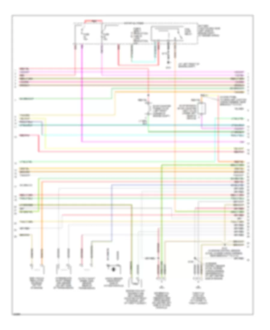
4.0L, Engine Performance Wiring Diagram (1 of 4) for Ford Explorer Sport Trac 2005
 https://portal-diagnostov.com/license.html
Automotive Electricians Portal FZCO
Automotive Electricians Portal FZCO
https://portal-diagnostov.com/license.html
https://portal-diagnostov.com/license.html
Automotive Electricians Portal FZCO
Automotive Electricians Portal FZCO
List of elements for 4.0L, Engine Performance Wiring Diagram (1 of 4) for Ford Explorer Sport Trac 2005:
- (act) sensor
- (at left front of engine compt)
- (behind left side of dash) data link connector (dlc)
- (case) ground
- (ckp) sensor (+)
- (ckp) sensor (-)
- (ect) sensor
- (ho2s) 3
- (in engine control sensor & fuel charge wiring harness, in breakout to c110)
- (maf) sensor rtn
- (not used)
- (pwr) ground
- (tft) sensor
- 4wd low ind
- A/c demand
- Air conditioning system
- Anti-theft system
- Battery junction box (bjb) (left side of engine compt, at fender apron)
- Brake pedal position switch resistor
- Central junction box (cjb) (behind left side of dash)
- Crankshaft position (ckp) sensor (lower right front of engine)
- Digital transmission range sensor
- Dlc bus (+)
- Dlc bus (-)
- Egr input
- Eprom power
- Fuel gauge
- Fuel pmp monitor
- Fuse 10a
- Fuse 15a
- Fuse 2 15a
- Fuse 3 30a
- G100 (at center rear of engine compt)
- G100 (center rear of engine compt)
- G104
- G109 (at center rear of engine compt)
- Hot at all times
- Hot in run or start
- Ignition coil
- Ignition coil (center rear of engine compartment)
- Ignition transformer capacitor (center rear of engine compartment)
- Indicator in
- Ks sensor
- Nca
- Not used
- Pcm power diode
- Pcm power relay
- Powertrain control module (pcm) (mounted through firewall)
- Pres sens input
- Red
- Red/pnk
- S105
- S145
- S148
- Sensor tr1
- Sensor tr2
- Sensor tr4
- Shift sol a
- Shift sol b
- Shift sol d
- Spark plugs
- St ctrl relay
- Starting/ charging system
- Trans ctrl (tcs)
- Tss sensor
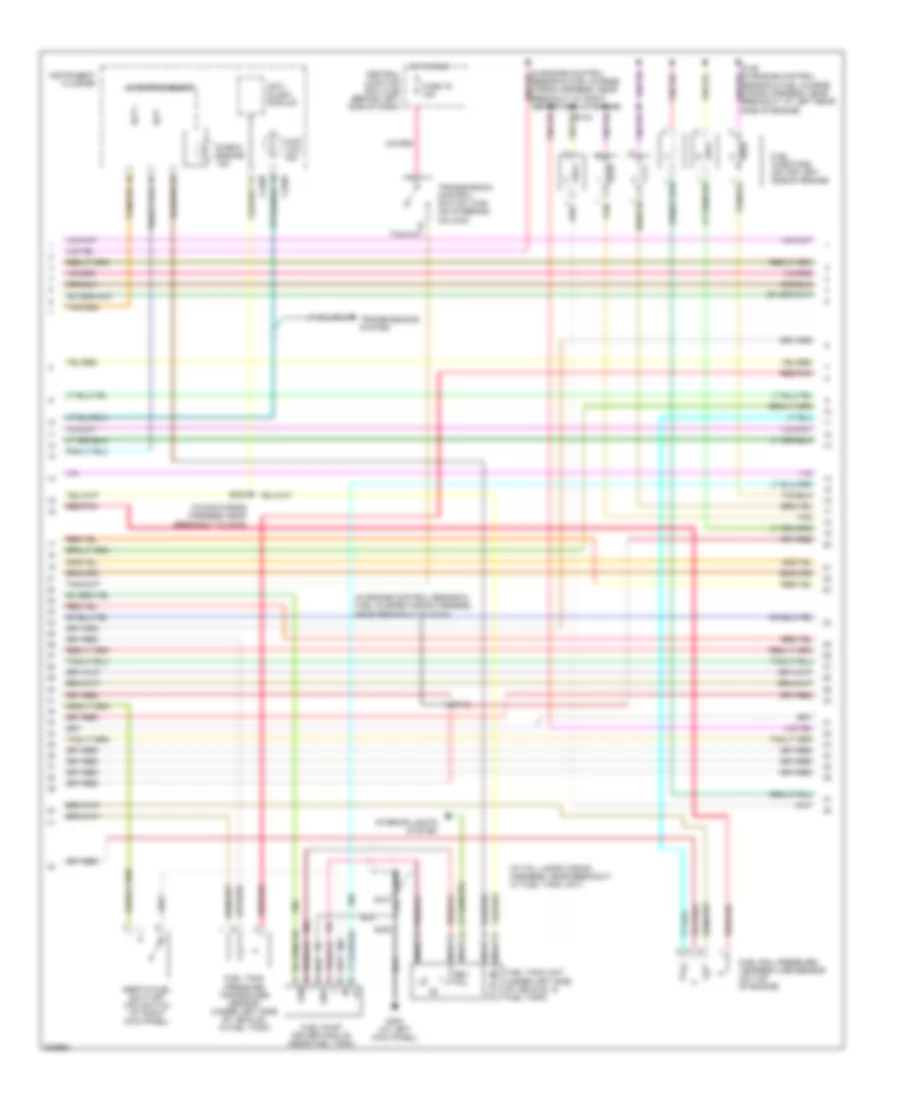
4.0L, Engine Performance Wiring Diagram (2 of 4) for Ford Explorer Sport Trac 2005
 https://portal-diagnostov.com/license.html
Automotive Electricians Portal FZCO
Automotive Electricians Portal FZCO
https://portal-diagnostov.com/license.html
https://portal-diagnostov.com/license.html
Automotive Electricians Portal FZCO
Automotive Electricians Portal FZCOList of elements for 4.0L, Engine Performance Wiring Diagram (2 of 4) for Ford Explorer Sport Trac 2005:
- (at left front of engine compt)
- (in dash panel to headlamp junction wiring harness, near breakout to c144)
- (in engine control sensor & fuel charge wiring harness, near breakout at left center side of engine)
- Battery junction box (bjb) (left side of engine compt, at fender apron)
- Differential pressure feedback egr (dpfe) sensor (on center left side of intake manifold)
- Egr vacuum regulator solenoid (on top of engine)
- Engine coolant temperature (ect) sensor (mounted on front of engine, left of throttle body)
- Evap canister purge valve (left front corner of engine compt)
- Evap emission (evap) canister vent valve (under left rear of vehicle)
- Fuel pump relay
- Fuse 15a
- Fuse 5 (early production) fuse 30 (late production) 20a
- G101
- Hot at all times
- Intermediate shaft speed (iss) sensor (on left side of transmission)
- Knock sensor (near right side of intake manifold)
- Output shaft speed (oss) sensor (rear of transmission)
- Red
- Red/pnk
- S111
- S137 (in engine control sensor & fuel charge wiring harness, near breakout to c110)
- S139
- Throttle position (tp) sensor (attached to throttle body)
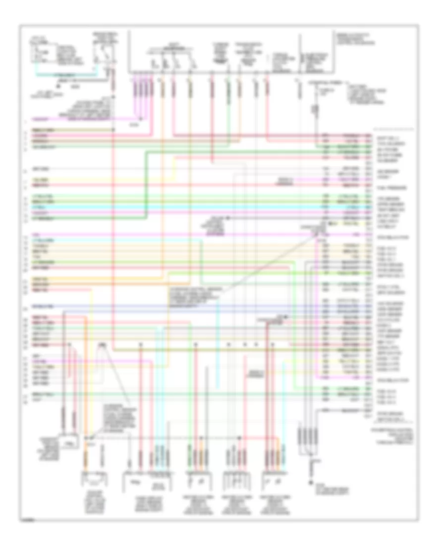
4.0L, Engine Performance Wiring Diagram (3 of 4) for Ford Explorer Sport Trac 2005
 https://portal-diagnostov.com/license.html
Automotive Electricians Portal FZCO
Automotive Electricians Portal FZCO
https://portal-diagnostov.com/license.html
https://portal-diagnostov.com/license.html
Automotive Electricians Portal FZCO
Automotive Electricians Portal FZCOList of elements for 4.0L, Engine Performance Wiring Diagram (3 of 4) for Ford Explorer Sport Trac 2005:
- (in engine control sensor & fuel charge wiring harness, near breakout to g100)
- (in main wiring harness, near breakout to c215)
- (in tail lamps wiring harness, near breakout at fuel tank unit)
- 4wd low ind
- Anti- slosh module
- C220a
- C220b
- Central junction box (cjb) (behind left side of dash)
- Check engine ind
- Fpm
- Fuel injectors (on top left side of engine)
- Fuel pump driver module (near fuel tank)
- Fuel rail pressure/ temperature sensor (on top of engine)
- Fuel tank pressure transducer sensor (under left side of vehicle, in fuel tank)
- Fuel tank unit (under left side of vehicle, in fuel tank)
- Fuse 19 15a
- G300 (at left kick panel)
- Gnd
- Hot in run
- Inertia fuel shut-off (ifs) switch (at right kick panel)
- Instrument cluster
- Interior lights system
- Microprocessor
- Nca
- Nca s410
- Red/pnk
- Rev pol
- S143
- S222
- S405
- Scp +
- Scp -
- Tan
- Transmission control switch (tcs) (on steering column)
- Transmissions system
4.0L, Engine Performance Wiring Diagram (4 of 4) for Ford Explorer Sport Trac 2005
 https://portal-diagnostov.com/license.html
Automotive Electricians Portal FZCO
Automotive Electricians Portal FZCO
https://portal-diagnostov.com/license.html
https://portal-diagnostov.com/license.html
Automotive Electricians Portal FZCO
Automotive Electricians Portal FZCOList of elements for 4.0L, Engine Performance Wiring Diagram (4 of 4) for Ford Explorer Sport Trac 2005:
- (at left kick panel)
- (b+) power
- (bpp) switch
- (cmp) sensor
- (dfpe) sensor
- (epc) solenoid
- (evap) purge
- (evap) vent
- (ho2s) 1
- (ho2s) 1 htr
- (ho2s) 2
- (ho2s) 2 htr
- (ho2s) 3 htr
- (iac) solenoid
- (in engine control sensor & fuel charge wiring harness, near breakout at rear center of engine compt)
- (in engine control sensor & fuel charge wiring harness, near breakout at rear center of engine)
- (maf) sensor
- (oss) sensor
- (pcm relay) pwr
- (pwr) ground
- (tcc) solenoid
- (tp) sensor
- (tr) sensor
- (vss) input
- 5r55e automatic transmission control solenoids
- A/c cycling
- A/c relay
- Air conditioning system
- Battery junction box (bjb) (left side of engine compt, at fender apron)
- Brake pedal position switch (bpp)
- Camshaft position sensor (on center left side of engine)
- Central junction box (cjb) (behind left side of dash)
- Cruise control, instrument cluster systems
- Electronic pressure control (epc) solenoid
- Ends in harness
- Fp rly ctrl
- Fuel inj 1
- Fuel inj 2
- Fuel inj 3
- Fuel inj 4
- Fuel inj 5
- Fuel inj 6
- Fuel pressure
- Fuse 24 10a
- Fuse 7.5a
- G109 (at center rear of engine compt)
- G3oo
- Heated oxygen sensor (ho2s) 11 (on exhaust pipe of engine)
- Heated oxygen sensor (ho2s) 12 (on exhaust pipe of engine)
- Heated oxygen sensor (ho2s) 21 (on exhaust pipe of engine)
- Hot at all times
- Idle air control (iac) valve (left side of intake manifold)
- Ignition coil 3
- Ignition coil 4
- Iss sensor
- Ks sensor
- Mass airflow (maf) sensor (right side of engine compt)
- Powertrain control module (pcm) (mounted through firewall)
- Red/pnk
- Ref volt
- S117 (in dash panel to headlamp junction wiring harness, near breakout at left center side of engine compt)
- S138
- S140
- S141
- S146
- S148
- S206
- Shift sol 3
- Shift solenoids
- Signal rtn
- Solid state
- Tan
- Temp sens sig
- Torque converter clutch (tcc) solenoid
- Transmission fluid temperature (tft) sensor
- Turbine shaft speed (tss) sensor

 Čeština
 Dansk
Dansk Deutsch
 Ελληνικά
 English
 English
 Español
 Suomi
Suomi Français
 Français
 עברית
עברית Hrvatski
 Magyar
 Italiano
 한국어
한국어 Nederlands
 Polski
 Português
 Português
 Română
 Русский
 Slovenčina
 Slovenščina
 Svenska
 Türkçe
 中文 (中国)
