ENGINE PERFORMANCE
3.7L
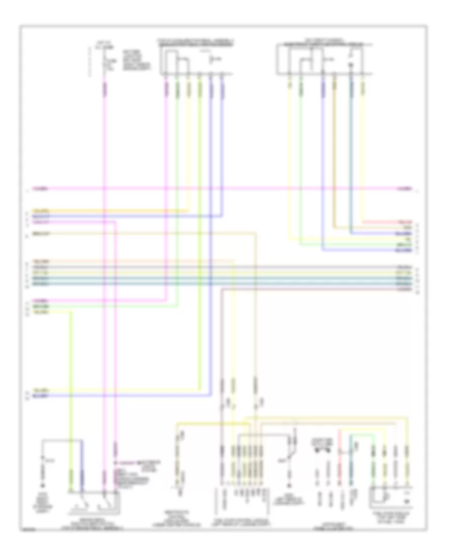
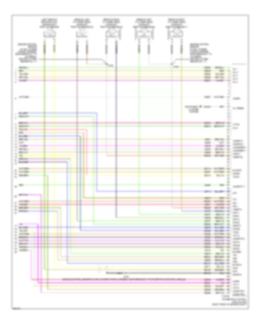
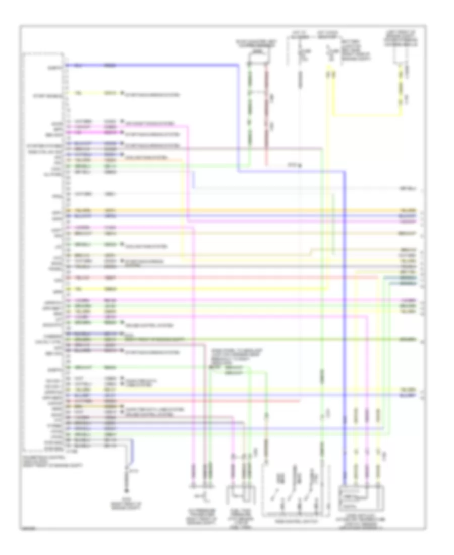
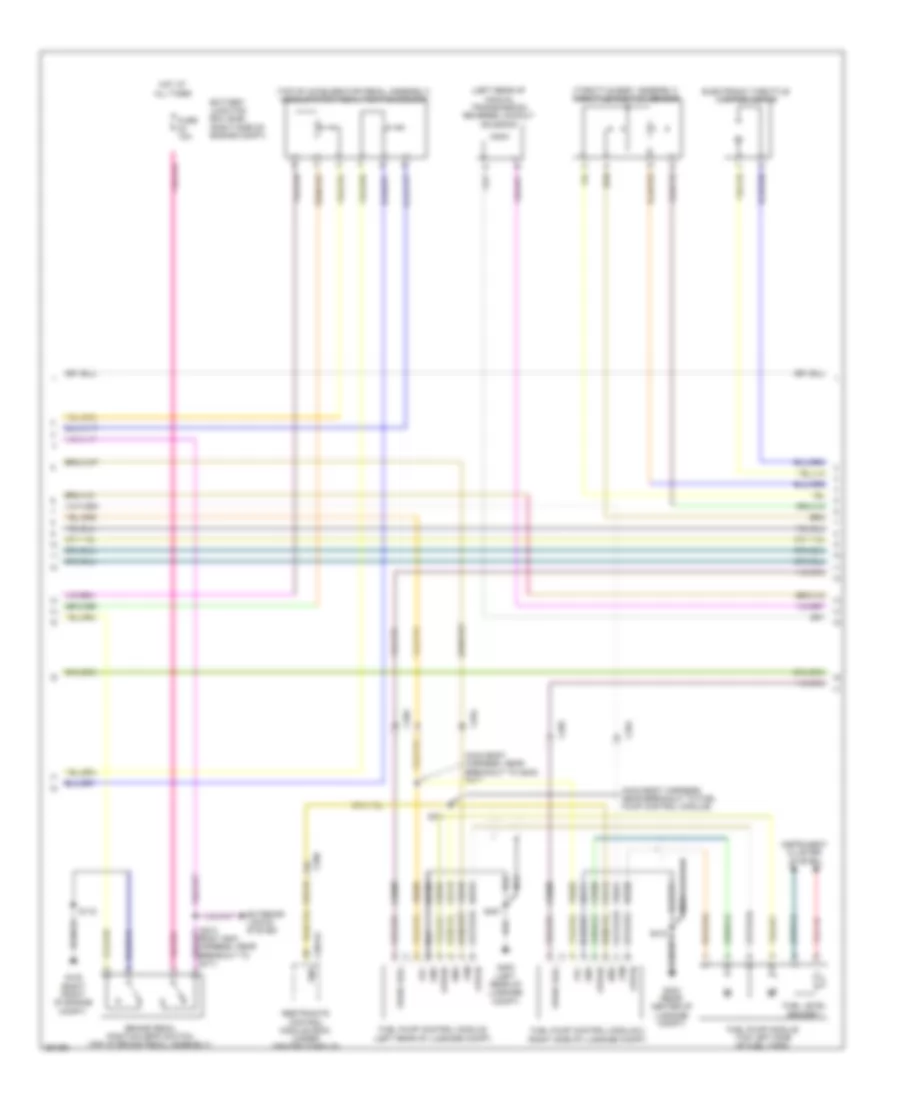
3.7L, Engine Performance Wiring Diagram (1 of 6) for Ford Mustang Shelby GT500 2013
 https://portal-diagnostov.com/license.html
Automotive Electricians Portal FZCO
Automotive Electricians Portal FZCO
https://portal-diagnostov.com/license.html
https://portal-diagnostov.com/license.html
Automotive Electricians Portal FZCO
Automotive Electricians Portal FZCO
List of elements for 3.7L, Engine Performance Wiring Diagram (1 of 6) for Ford Mustang Shelby GT500 2013:
- (left front of engine compt) power steering control module
- (under center rear of vehicle) evaporative emission (evap) canister vent valve
- A/c pressure transducer (right front of engine compt)
- Accr
- Acpt
- Air conditioning system
- App
- App2
- Apprtn
- Apprtn2
- Appvref
- Appvref2
- Battery junction box (bjb) (right side of engine compt)
- Boo
- Bps
- C110
- C1381b
- C1463b
- C219
- C264
- C406
- Canv
- Casegnd
- Cbb45
- Cbb47
- Ccb08
- Cdb08
- Cdc10
- Cdc12
- Cdc15
- Cdc35
- Cdc54
- Ce114
- Ce302
- Ce509
- Ce608
- Cec01
- Cec02
- Cet35
- Cet42
- Ch302
- Computer data lines system
- Cooling fans system
- Cruise control system
- Digital
- Feps
- Fpc
- Fpm
- Ftp
- Ftpref
- Fuel tank pressure (ftp) sensor (top of fuel tank)
- Fuse 10a
- Fuse 5a
- G102 (right front of engine compt)
- G103 (right front of engine compt)
- Gd119
- Gencom
- Genmon
- Hfc
- Hot at all times
- Hot in run or start
- Hs can +
- Hs can -
- Iat
- Injpwrm
- Ispr
- Kapwr
- Le136
- Le137
- Le230
- Le423
- Lfc
- Maf
- Mass air flow/ intake air temperature (maf/iat) sensor (air intake assembly)
- Pcm rly ctrl
- Powertrain control module (pcm) (right front of engine compt)
- Pwr gnd
- Re136
- Re137
- Re320
- Re405
- Res08
- S115
- S143
- S199 (dash panel to headlamp junction harness near breakout to right headlamp)
- Sbb23
- Sccs
- Sccs rtn
- Shift dn
- Shift interlock system
- Shift up
- Sigrtn
- Smc
- Smcs
- Start
- Starting/charging system
- Transmission shift selector (under center console)
- Vdb04
- Vdb05
- Ve225
- Ve518
- Ve701
- Ve702
- Ve740
- Ve807
- Ve922
- Ves10
- Vh433
- Vpwr
- Vref
- Vref 5v
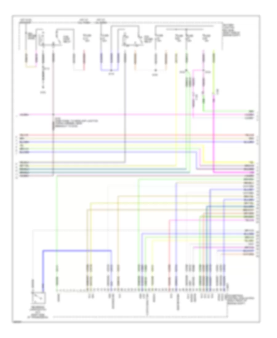
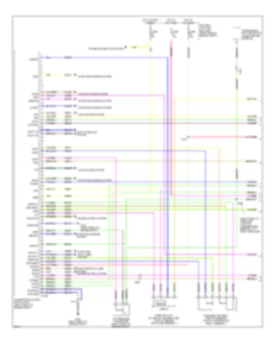
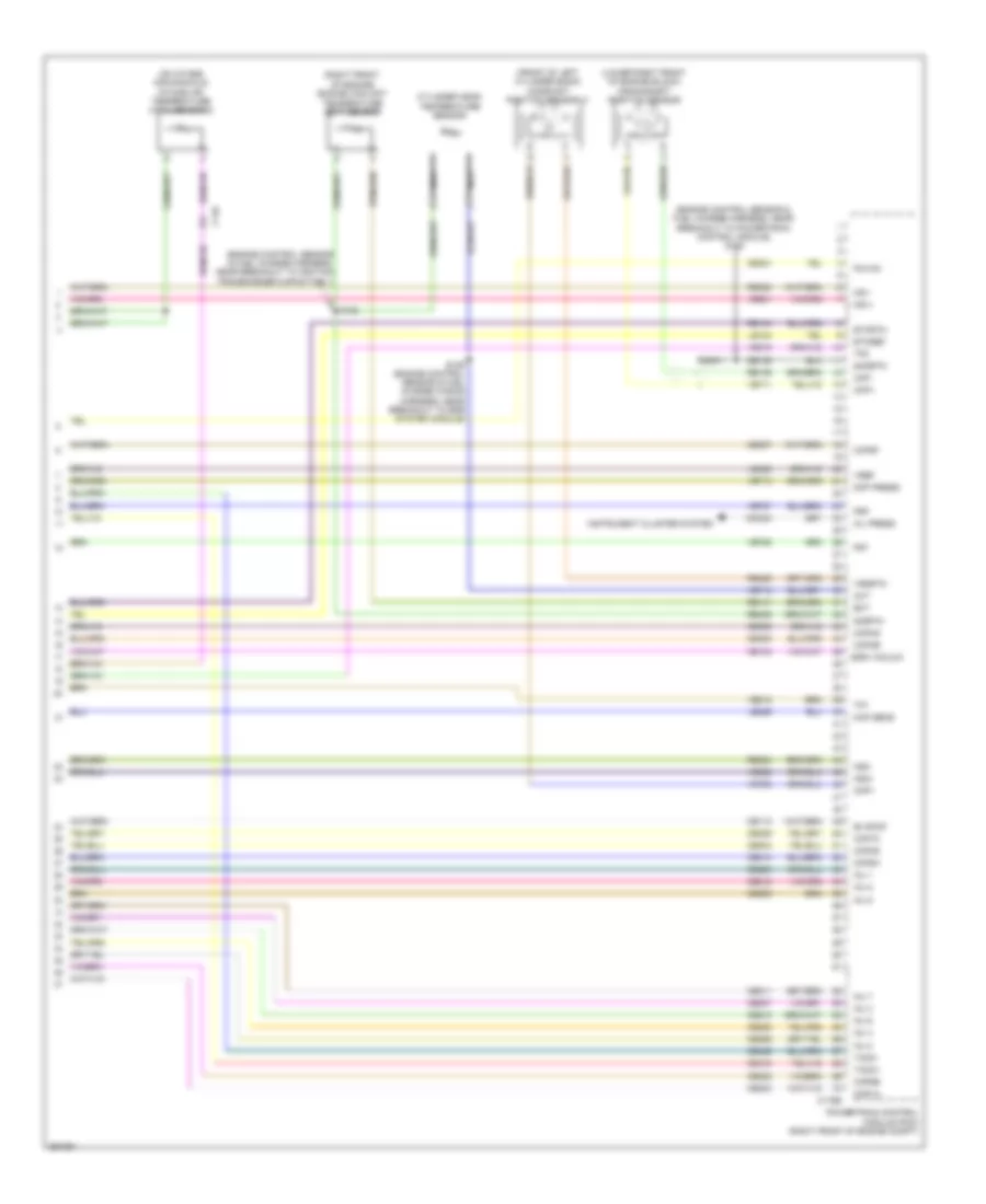
3.7L, Engine Performance Wiring Diagram (2 of 6) for Ford Mustang Shelby GT500 2013
 https://portal-diagnostov.com/license.html
Automotive Electricians Portal FZCO
Automotive Electricians Portal FZCO
https://portal-diagnostov.com/license.html
https://portal-diagnostov.com/license.html
Automotive Electricians Portal FZCO
Automotive Electricians Portal FZCOList of elements for 3.7L, Engine Performance Wiring Diagram (2 of 6) for Ford Mustang Shelby GT500 2013:
- (on throttle body) electronic throttle control module
- (top of accelerator pedal assembly) accelerator pedal position sensor
- 1 rtn
- Battery junction box (bjb) (right side of engine compt)
- Brake pedal position (bpp) switch (top of brake pedal assembly)
- C2041a
- C260
- C264
- C265
- Ce515
- Ce608
- Computer data lines system
- Cr113
- Ens
- Exterior lights system
- Fp pwr
- Fp rtn
- Fpc
- Fpm
- Fuel lvl
- Fuel lvl 1
- Fuel pump control module (left rear of luggage compt)
- Fuel pump module (top left side of fuel tank)
- Fuse 10a
- G102 (right front of engine compt)
- G400 (left rear of luggage compt)
- Gd109
- Gnd
- Hot at all times
- Hs can +
- Hs can -
- Instrument panel cluster (ipc)
- Nca
- Re515
- Restraints control module (rcm) (under center console)
- Rmc32
- S115
- S213 (body main wiring harness, near breakout to c211)
- S407
- Ve225
- Ve518
- Vmc11
- Vpwr fuel
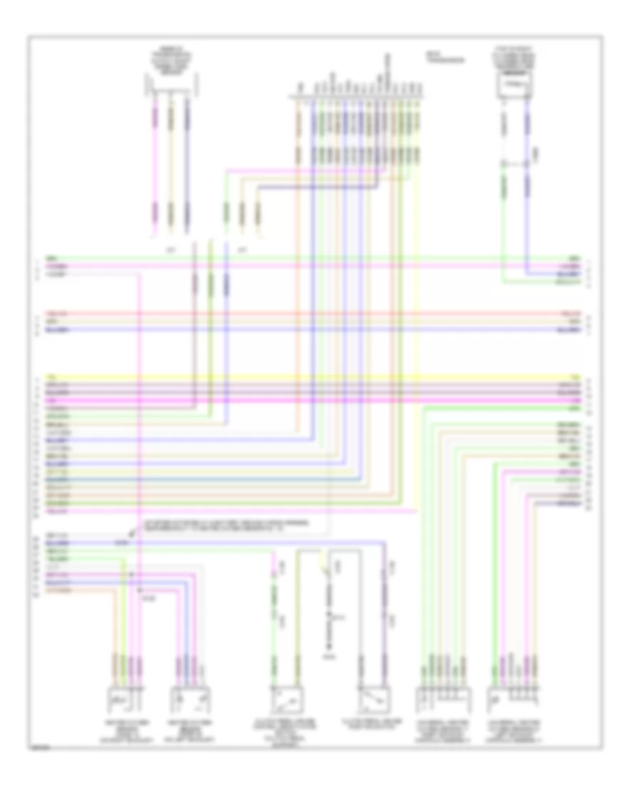
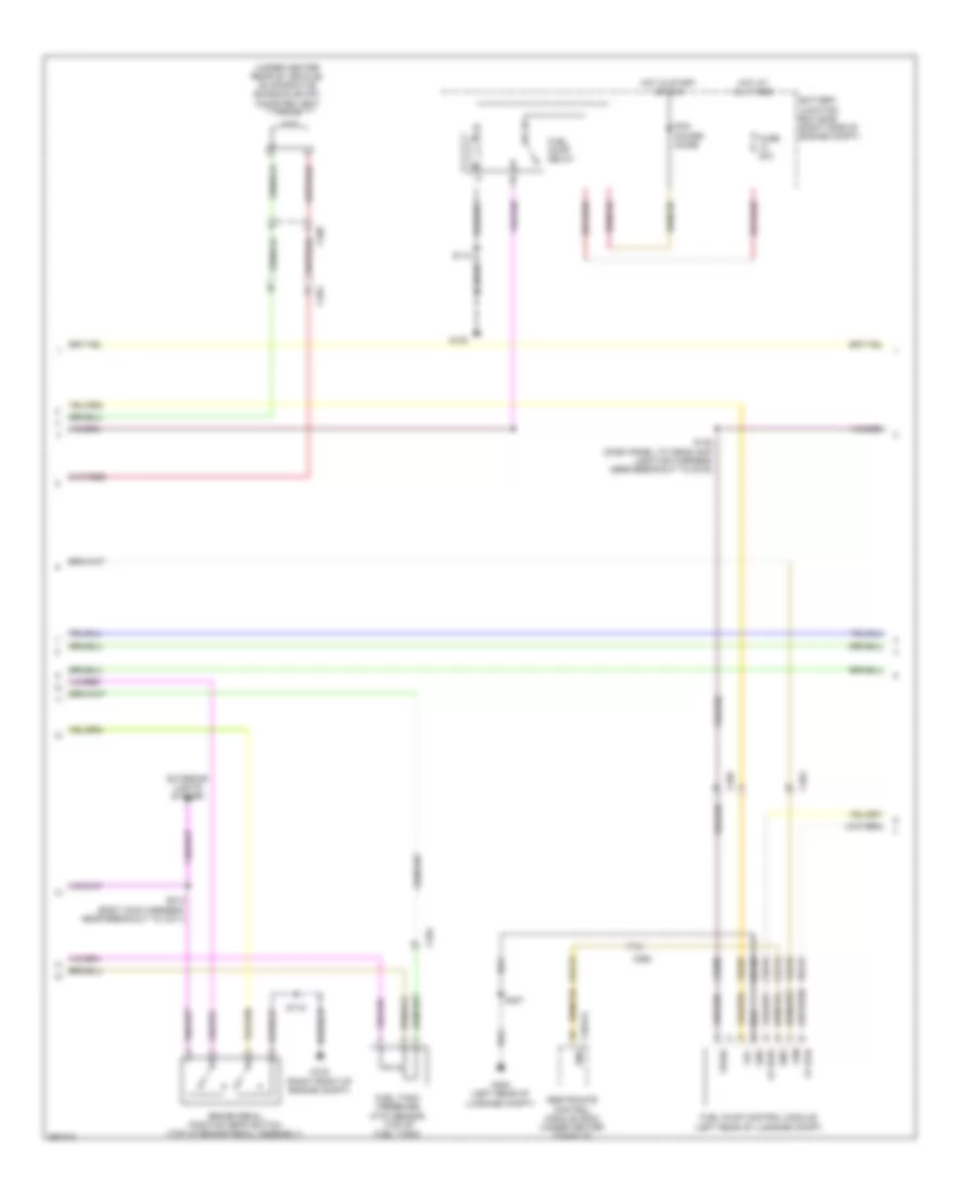
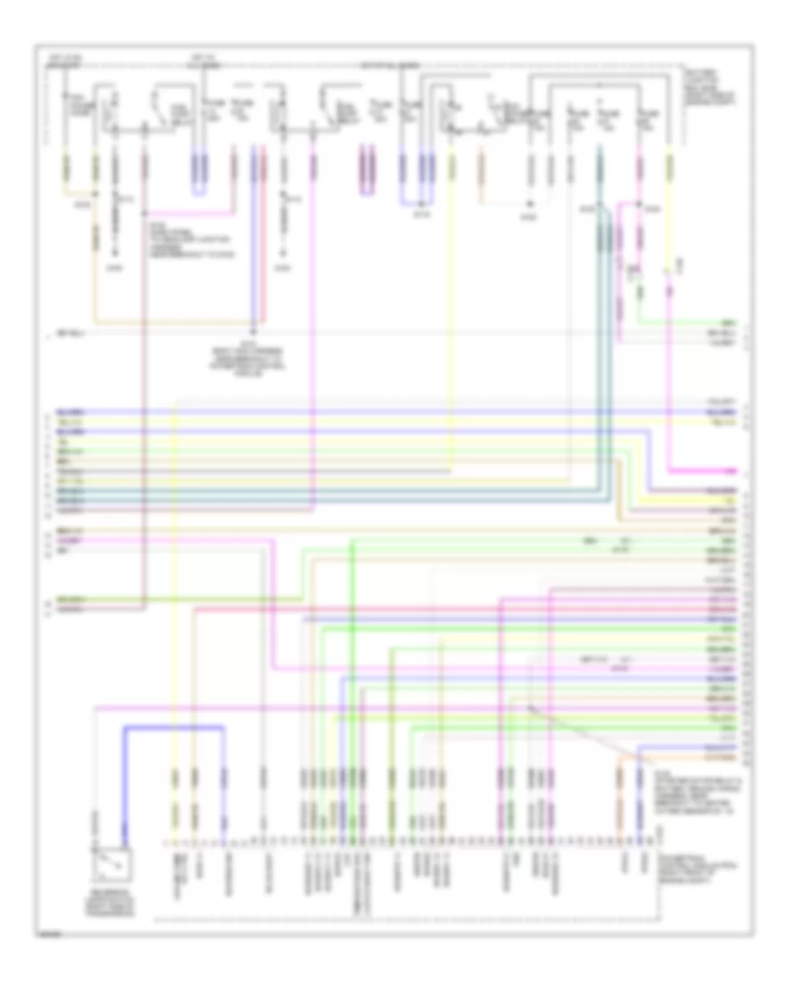
3.7L, Engine Performance Wiring Diagram (3 of 6) for Ford Mustang Shelby GT500 2013
 https://portal-diagnostov.com/license.html
Automotive Electricians Portal FZCO
Automotive Electricians Portal FZCO
https://portal-diagnostov.com/license.html
https://portal-diagnostov.com/license.html
Automotive Electricians Portal FZCO
Automotive Electricians Portal FZCOList of elements for 3.7L, Engine Performance Wiring Diagram (3 of 6) for Ford Mustang Shelby GT500 2013:
- Battery junction box (bjb) (right side of engine compt)
- C110
- C1381t
- C146
- Ce233
- Ce234
- Ce903
- Ce904
- Cet05
- Cet06
- Cet07
- Cet08
- Cet09
- Cet10
- Cet18
- Cet25
- Cet47
- Cet60
- Clutch deact sw
- Cpp
- Fuel pump relay
- Fuse 15a
- Fuse 20a
- Fuse 30a
- G100
- Ho2s12
- Ho2s22
- Hot at all times
- Hot in on or start
- Htr12
- Htr22
- Le111
- Oss
- Pc1
- Pc2
- Pc3
- Pc4
- Pc5
- Pc6
- Pcm power diode
- Pcm power relay
- Powertrain control module (pcm) (right front of engine compt)
- Re406
- Ret24
- Reverse sw
- Reversing lamps switch (m/t) (right side of transmission)
- S112
- S116
- S120
- S123
- S124
- S135 (dash panel to headlamp junction wiring harness, near breakout to g100)
- Sigrtn
- Sigrtn/trgnd
- Ss1
- Tft
- Tr p
- Tspc
- Tss
- Vbpwr
- Ve731
- Ve733
- Vet26
- Vet27
- Vet33
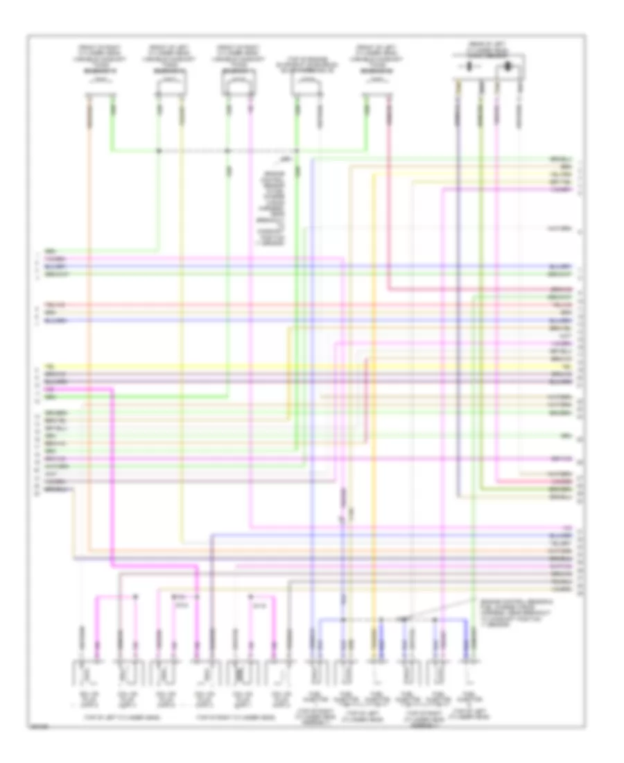
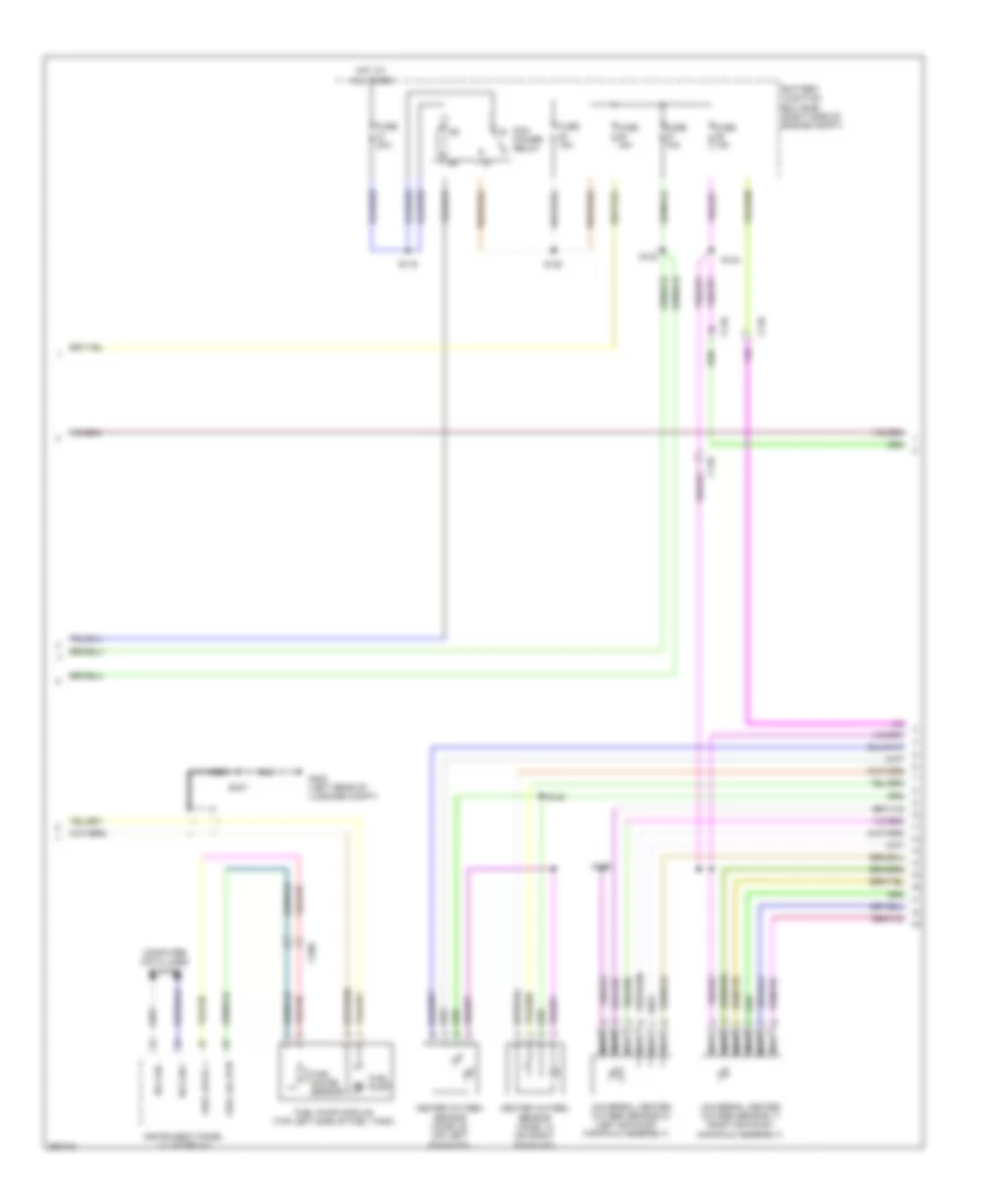
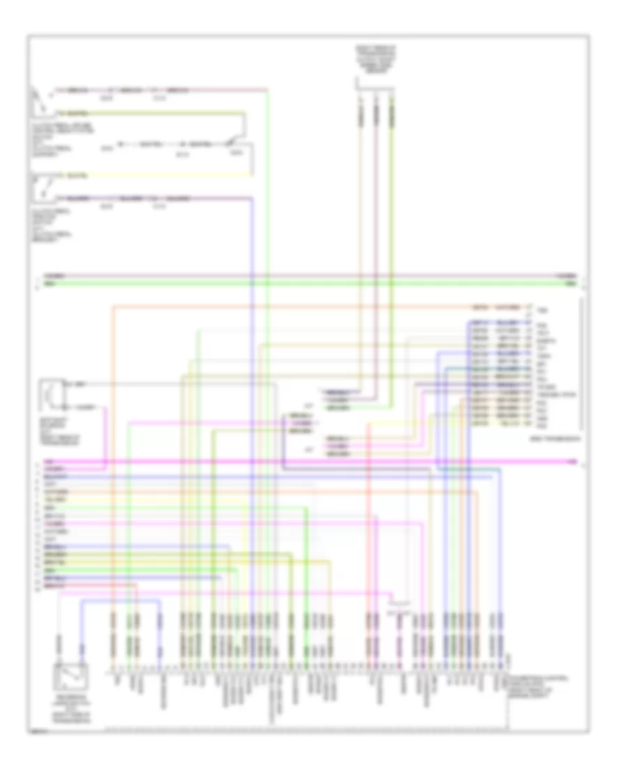
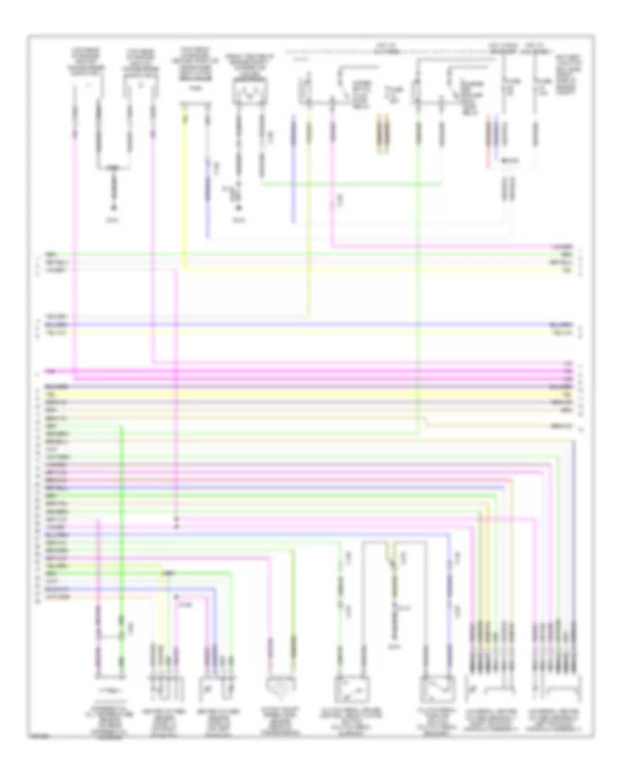
3.7L, Engine Performance Wiring Diagram (4 of 6) for Ford Mustang Shelby GT500 2013
 https://portal-diagnostov.com/license.html
Automotive Electricians Portal FZCO
Automotive Electricians Portal FZCO
https://portal-diagnostov.com/license.html
https://portal-diagnostov.com/license.html
Automotive Electricians Portal FZCO
Automotive Electricians Portal FZCOList of elements for 3.7L, Engine Performance Wiring Diagram (4 of 6) for Ford Mustang Shelby GT500 2013:
- (rear of transmission) output shaft speed (oss) sensor
- (starter motor relay & battery ground wiring harness, near breakout to heated oxygen sensor no. 12)
- (top of right cylinder head) cylinder head temperature sensor
- 6r 80 transmission
- A/t
- C1026
- C110
- C215
- Cet05
- Cet06
- Cet07
- Cet08
- Cet09
- Cet10
- Cet18
- Cet25
- Cet60
- Clutch pedal cruise control deactivator switch (clutch pedal support)
- Clutch pedal cruise position switch
- G104
- Heated oxygen sensor (ho2s) 12 (on right exhaust)
- Heated oxygen sensor (ho2s) 22 (on left exhaust)
- Le111
- M/t
- Oss
- Pc1
- Pc2
- Pc3
- Pc4
- Pc5
- Pc6
- Re406
- Ret24
- S113
- S138
- S139
- Sig rtn
- Ss1
- Tft
- Tr gnd
- Tr p
- Tspc
- Tss
- Tss/oss vpwr
- Universal heated oxygen sensor 11 (right exhaust manifold assembly)
- Universal heated oxygen sensor 21 (left exhaust manifold assembly)
- Vet26
- Vet27
- Vet33
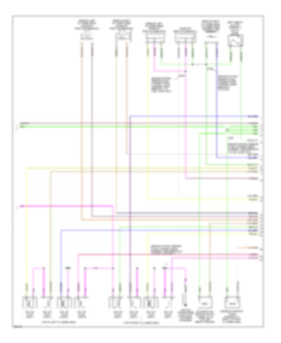
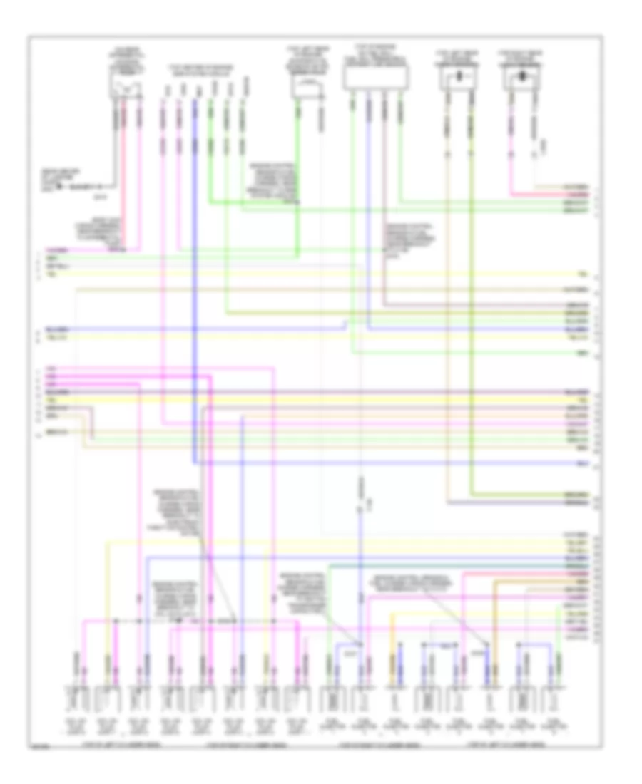
3.7L, Engine Performance Wiring Diagram (5 of 6) for Ford Mustang Shelby GT500 2013
 https://portal-diagnostov.com/license.html
Automotive Electricians Portal FZCO
Automotive Electricians Portal FZCO
https://portal-diagnostov.com/license.html
https://portal-diagnostov.com/license.html
Automotive Electricians Portal FZCO
Automotive Electricians Portal FZCOList of elements for 3.7L, Engine Performance Wiring Diagram (5 of 6) for Ford Mustang Shelby GT500 2013:
- (engine control sensor & fuel charge wiring harness, near breakout to camshaft position 11 sensor)
- (front of left cylinder head) variable camshaft timing solenoid 21
- (front of left cylinder head) variable camshaft timing solenoid 22
- (front of right cylinder head) variable camshaft timing solenoid 11
- (front of right cylinder head) variable camshaft timing solenoid 12
- (rear of left cylinder head) knock sensor
- (top of engine) evaporative emission (evap) purge valve
- (top of left cylinder head)
- (top of right cylinder head assembly)
- (top of right cylinder head)
- C146
- Coil on plug (cop) 1
- Coil on plug (cop) 2
- Coil on plug (cop) 3
- Coil on plug (cop) 4
- Coil on plug (cop) 5
- Coil on plug (cop) 6
- Fuel injector
- Fuel injector (top of left cylinder head)
- Fuel injector (top of right cylinder head assembly)
- S101
- S104
- S107
- S119
- Tan
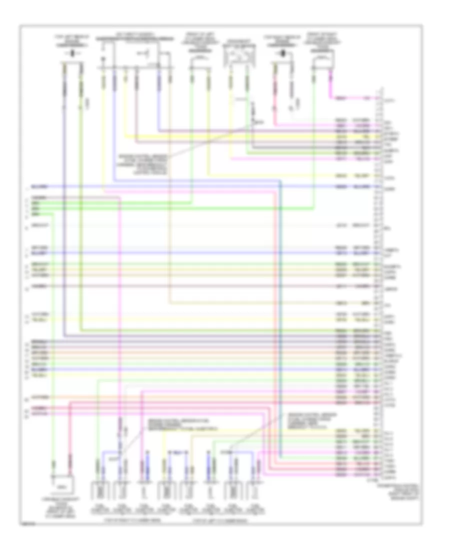
3.7L, Engine Performance Wiring Diagram (6 of 6) for Ford Mustang Shelby GT500 2013
 https://portal-diagnostov.com/license.html
Automotive Electricians Portal FZCO
Automotive Electricians Portal FZCO
https://portal-diagnostov.com/license.html
https://portal-diagnostov.com/license.html
Automotive Electricians Portal FZCO
Automotive Electricians Portal FZCOList of elements for 3.7L, Engine Performance Wiring Diagram (6 of 6) for Ford Mustang Shelby GT500 2013:
- (engine control sensor & fuel charge wiring harness, near breakout to powertrain control module)
- (engine control sensor & fuel charge wiring harness, near breakout to universal heated oxygen sensor no. 11)
- (left rear of engine block) crankshaft position sensor
- (rear of left cylinder head) camshaft position sensor 21
- (rear of left cylinder head) camshaft position sensor 22
- (rear of right cylinder head) camshaft position sensor 11
- (rear of right cylinder head) camshaft position sensor 12
- C1381e
- Ce113
- Ce205
- Ce206
- Ce207
- Ce208
- Ce209
- Ce210
- Ce235
- Ce236
- Ce303
- Ce304
- Ce305
- Ce306
- Ce307
- Ce308
- Ce412
- Ce421
- Ce422
- Ce426
- Ce442
- Ce443
- Cht
- Ckp+
- Ckp-
- Cmc24
- Cmp11
- Cmp12
- Cmp21
- Cmp22
- Cop1a
- Cop2c
- Cop3e
- Cop4b
- Cop5d
- Cop6f
- De135
- Etcref
- Etcrtn
- Evapcp
- Inj 1
- Inj 2
- Inj 3
- Inj 4
- Inj 5
- Inj 6
- Instrument cluster system
- Ks1+
- Ks1-
- Ks2+
- Ks2-
- Le134
- Le448
- Le449
- Le450
- Le451
- Le452
- Le453
- Nca
- Oil press
- Powertrain control module (pcm) (right front of engine compt)
- Re134
- Re135
- Re323
- Re324
- Re405
- Re429
- S108
- S145
- S146
- Shdrtn
- Sigrtn
- Tacm+
- Tacm-
- Tp1
- Tp2
- Uo2s11
- Uo2s21
- Uo2sgref11
- Uo2sgref21
- Uo2shtr11
- Uo2shtr21
- Uo2spc11
- Uo2spc21
- Uo2spct11
- Uo2spct21
- Vct11
- Vct12
- Vct21
- Vct22
- Ve706
- Ve707
- Ve711
- Ve712
- Ve801
- Ve802
- Ve818
- Ve819
- Ve826
- Ve827
- Vrsrtn
- Vrsrtn2
5.0L
5.0L, Engine Performance Wiring Diagram (1 of 6) for Ford Mustang Shelby GT500 2013
 https://portal-diagnostov.com/license.html
Automotive Electricians Portal FZCO
Automotive Electricians Portal FZCO
https://portal-diagnostov.com/license.html
https://portal-diagnostov.com/license.html
Automotive Electricians Portal FZCO
Automotive Electricians Portal FZCOList of elements for 5.0L, Engine Performance Wiring Diagram (1 of 6) for Ford Mustang Shelby GT500 2013:
- (dash panel to headlamp junction harness near breakout to right headlamp)
- A/c pressure transducer (right front of engine compt)
- Accelerator pedal position sensor (top of accelerator pedal assembly)
- Accr
- Acpt
- Air conditioning system
- App1
- App2
- Apprtn1
- Apprtn2
- Appvref2
- Appvrfe1
- Battery junction box (bjb) (right side of engine compt)
- Bpp
- Bps
- C175b
- C219
- C264
- Canv
- Case gnd
- Cbb45
- Cbb47
- Ccb08
- Cdb08
- Cdc10
- Cdc12
- Cdc15
- Cdc35
- Cdc54
- Ce114
- Ce302
- Ce509
- Ce608
- Cec01
- Cec02
- Cet35
- Cet42
- Ch302
- Computer data lines system
- Computer data lines system cruise control system
- Cooling fans system
- Cruise control system
- Digital
- Feps
- Fpc
- Fpm
- Ftp
- Ftpref
- Fuse 10a
- Fuse 5a
- G102 (right front of engine compt)
- G103 (right front of engine compt)
- Gd119
- Gencom
- Genmon
- Hfc
- Hot at all times
- Hot in start or run
- Hs can +
- Hs can -
- Iat
- Injpwrm
- Ispr
- Kapwr
- Le136
- Le137
- Le230
- Le423
- Lfc
- Maf
- Mass air flow/ intake air temperature (maf/iat) sensor (air intake assembly)
- Pcmrc
- Power distribution system
- Powertrain control module (pcm) (right front of engine compt)
- Pwr gnd
- Re136
- Re137
- Re320
- Re405
- Res08
- S115
- S143
- S199
- Sbb23
- Sccs
- Sccs rtn
- Shift dn
- Shift interlock system
- Shift up
- Sigrtn
- Smc
- Smcs
- Start
- Starting/charging system
- Transmission shift selector (under center console)
- Vdb04
- Vdb05
- Ve225
- Ve518
- Ve701
- Ve702
- Ve740
- Ve807
- Ve922
- Ves10
- Vh433
- Vpwr
- Vref
- Vref 5v
5.0L, Engine Performance Wiring Diagram (2 of 6) for Ford Mustang Shelby GT500 2013
 https://portal-diagnostov.com/license.html
Automotive Electricians Portal FZCO
Automotive Electricians Portal FZCO
https://portal-diagnostov.com/license.html
https://portal-diagnostov.com/license.html
Automotive Electricians Portal FZCO
Automotive Electricians Portal FZCOList of elements for 5.0L, Engine Performance Wiring Diagram (2 of 6) for Ford Mustang Shelby GT500 2013:
- (under center rear of vehicle) evaporative emission (evap) canister vent valve
- Battery junction box (bjb) (right side of engine compt)
- Brake pedal position (bpp) switch (top of brake pedal assembly)
- C2041a
- C260
- C264
- C265
- C406
- Ce515
- Ce608
- Cr113
- Ens
- Exterior lights system
- Fp pwr
- Fp rtn
- Fpc
- Fpm
- Fuel pump control module (left rear of luggage compt)
- Fuel pump relay
- Fuel tank pressure (ftp) sensor (top of fuel tank)
- Fuse 20a
- G100
- G102 (right front of engine compt)
- G400 (left rear of luggage compt)
- Gd109
- Gnd
- Hot at all times
- Hot in start or run
- Pcm power diode
- Re515
- Restraints control module (rcm) (under center console)
- S112
- S115
- S135 (dash panel to headlamp junction harness near breakout to g100)
- S213 (body main harness, near breakout to c211)
- S407
- Ve225
- Ve518
- Vpwr
5.0L, Engine Performance Wiring Diagram (3 of 6) for Ford Mustang Shelby GT500 2013
 https://portal-diagnostov.com/license.html
Automotive Electricians Portal FZCO
Automotive Electricians Portal FZCO
https://portal-diagnostov.com/license.html
https://portal-diagnostov.com/license.html
Automotive Electricians Portal FZCO
Automotive Electricians Portal FZCOList of elements for 5.0L, Engine Performance Wiring Diagram (3 of 6) for Ford Mustang Shelby GT500 2013:
- (left exhaust manifold assembly)
- Battery junction box (bjb) (right side of engine compt)
- C110
- C146
- C260
- Computer data lines system
- Fuel gauge sensor
- Fuel lel rtn
- Fuel level 1
- Fuel pump
- Fuel pump module (top left side of fuel tank)
- Fuse 15a
- Fuse 30a
- G400 (left rear of luggage compt)
- Heated oxygen sensor (ho2s) 12 (on right exhaust)
- Heated oxygen sensor (ho2s) 22 (on left exhaust)
- Hot at all times
- Hs can +
- Hs can -
- Instrument panel cluster (ic)
- Nca
- Pcm power relay
- S116
- S120
- S123
- S124
- S139
- S140
- S407
- Universal heated oxygen sensor 11 (right exhaust manifold assembly)
- Universal heated oxygen sensor 21
5.0L, Engine Performance Wiring Diagram (4 of 6) for Ford Mustang Shelby GT500 2013
 https://portal-diagnostov.com/license.html
Automotive Electricians Portal FZCO
Automotive Electricians Portal FZCO
https://portal-diagnostov.com/license.html
https://portal-diagnostov.com/license.html
Automotive Electricians Portal FZCO
Automotive Electricians Portal FZCOList of elements for 5.0L, Engine Performance Wiring Diagram (4 of 6) for Ford Mustang Shelby GT500 2013:
- (right rear of transmission) output shaft speed (oss) sensor
- 6r80 transmission
- A/t
- C110
- C175t
- C215
- Ce233
- Ce234
- Ce235
- Ce236
- Ce903
- Ce904
- Cet05
- Cet06
- Cet07
- Cet08
- Cet09
- Cet10
- Cet18
- Cet25
- Cet43
- Cet47
- Cet60
- Clutch deact sw
- Clutch pedal cruise control deactivator switch (m/t) (clutch pedal support)
- Clutch pedal position switch (m/t) (clutch pedal bracket)
- Cpp
- G104
- Ho2s12
- Ho2s22
- Htr12
- Htr22
- Le111
- Le448
- Le449
- Le450
- Le451
- Le452
- Le453
- M/t
- Oss
- Pc1
- Pc2
- Pc3
- Pc4
- Pc5
- Pc6
- Powertrain control module (pcm) (right front of engine compt)
- Re242
- Re406
- Ret24
- Reverse sw
- Reversing lamps switch (m/t) (right side of transmission)
- S113
- Sigrtn
- Skip shift sol
- Skip shift solenoid (m/t) (right rear of transmission)
- Ss1
- Tft
- Tr gnd
- Tr p
- Tr-p
- Tspc
- Tss
- Tss/oss vpwr
- Uo2s11
- Uo2s21
- Uo2sgref11
- Uo2sgref21
- Uo2shtr11
- Uo2shtr21
- Uo2spc11
- Uo2spc21
- Uo2spct11
- Uo2spct21
- Ve731
- Ve733
- Ve826
- Ve827
- Vet26
- Vet27
- Vet33
- Vpwr
5.0L, Engine Performance Wiring Diagram (5 of 6) for Ford Mustang Shelby GT500 2013
 https://portal-diagnostov.com/license.html
Automotive Electricians Portal FZCO
Automotive Electricians Portal FZCO
https://portal-diagnostov.com/license.html
https://portal-diagnostov.com/license.html
Automotive Electricians Portal FZCO
Automotive Electricians Portal FZCOList of elements for 5.0L, Engine Performance Wiring Diagram (5 of 6) for Ford Mustang Shelby GT500 2013:
- (engine control sensor & fuel charge wiring harness, near breakout to c1019)
- (engine control sensor & fuel charge wiring harness, near breakout to fuel injector 1)
- (engine control sensor & fuel charge wiring harness, near breakout to fuel injector 3)
- (engine control sensor & fuel charge wiring harness, near breakout to fuel injector 4)
- (left side of oil pan assembly) low oil level switch
- (rear of left cylinder head) camshaft position sensor 21
- (rear of left cylinder head) camshaft position sensor 22
- (rear of right cylinder head) camshaft position sensor 12
- (rear of right cylinder head) cylinder head temperature sensor
- (top of left cylinder head)
- (top of right cylinder head)
- Camshaft position sensor 11
- Coil on plug (cop) 1
- Coil on plug (cop) 2
- Coil on plug (cop) 3
- Coil on plug (cop) 4
- Coil on plug (cop) 5
- Coil on plug (cop) 6
- Coil on plug (cop) 7
- Coil on plug (cop) 8
- Evaporative emission (evap) purge valve (top left rear of engine)
- Ignition transformer capacitor 1 (top rear of engine)
- S101
- S102
- S104
- S119
- S136
- Variable camshaft timing solenoid 12 (front of right cylinder head)
5.0L, Engine Performance Wiring Diagram (6 of 6) for Ford Mustang Shelby GT500 2013
 https://portal-diagnostov.com/license.html
Automotive Electricians Portal FZCO
Automotive Electricians Portal FZCO
https://portal-diagnostov.com/license.html
https://portal-diagnostov.com/license.html
Automotive Electricians Portal FZCO
Automotive Electricians Portal FZCOList of elements for 5.0L, Engine Performance Wiring Diagram (6 of 6) for Ford Mustang Shelby GT500 2013:
- (engine control sensor & fuel charge harness, near breakout to fuel injector 3)
- (engine control sensor & fuel charge wiring harness, near breakout to c1313)
- (engine control sensor & fuel charge wiring harness, near breakout to powertrain control module)
- (front of left cylinder head) variable camshaft timing solenoid 21
- (front of right cylinder head) variable camshaft timing solenoid 11
- (on throttle body) electronic throttle control module
- (top left rear of engine) knock sensor 2
- (top of left cylinder bank)
- (top of right cylinder head)
- (top right rear of engine) knock sensor 1
- C1019
- C146
- C175e
- Ce113
- Ce205
- Ce206
- Ce207
- Ce208
- Ce209
- Ce210
- Ce211
- Ce212
- Ce303
- Ce304
- Ce305
- Ce306
- Ce307
- Ce308
- Ce309
- Ce310
- Ce412
- Ce421
- Ce422
- Ce426
- Ce442
- Ce443
- Cht
- Ckp+
- Ckp-
- Cmp11
- Cmp12
- Cmp21
- Cmp22
- Cop1a
- Cop2h
- Cop3f
- Cop4c
- Cop5b
- Cop6e
- Cop7g
- Cop8d
- Crankshaft position sensor
- De135
- E-sigrtn
- Eol
- Etcref
- Etcrtn
- Evapcp
- Fuel injector
- Inj 1
- Inj 2
- Inj 3
- Inj 4
- Inj 5
- Inj 6
- Inj 7
- Inj 8
- Ks1+
- Ks1-
- Ks2+
- Ks2-
- Le111
- Le134
- Le142
- Nca
- Powertrain control module (pcm) (right front of engine compt)
- Re134
- Re135
- Re323
- Re324
- Re405
- Re429
- S107
- S108
- S109
- Shdrtn
- Tacm+
- Tacm-
- Tp1
- Tp2
- Variable camshaft timing solenoid 22 (front of left cylinder head)
- Vbpwr
- Vct11
- Vct12
- Vct21
- Vct22
- Ve706
- Ve707
- Ve711
- Ve712
- Ve736
- Ve738
- Ve801
- Ve802
- Ve818
- Ve819
- Vrsrtn
- Vrsrtn 2
5.8L SUPERCHARGED
5.8L Supercharged, Engine Performance Wiring Diagram (1 of 6) for Ford Mustang Shelby GT500 2013
 https://portal-diagnostov.com/license.html
Automotive Electricians Portal FZCO
Automotive Electricians Portal FZCO
https://portal-diagnostov.com/license.html
https://portal-diagnostov.com/license.html
Automotive Electricians Portal FZCO
Automotive Electricians Portal FZCOList of elements for 5.8L Supercharged, Engine Performance Wiring Diagram (1 of 6) for Ford Mustang Shelby GT500 2013:
- (dash panel to headlamp junction harness near breakout to right headlamp) s199
- (left front of engine compt) power steering control module
- A/c pressure transducer (right front of engine compt)
- Accr
- Acp
- Acpt
- Air conditioning system
- App1
- App2
- Apprtn1
- Apprtn2
- Appvref1
- Appvref2
- Battery junction box (bjb) (right side of engine compt)
- Bpp
- Bps
- C110
- C1463b
- C175b
- C192
- C211
- C264
- C406
- Cac rly ctrl
- Canv
- Casegnd
- Cbb38
- Cbb45
- Cbb47
- Ccb08
- Cdb08
- Cdc10
- Cdc12
- Cdc15
- Cdc35
- Cdc54
- Ce114
- Ce302
- Ce509
- Ce918
- Cec01
- Cec02
- Ch302
- Cmc29
- Computer data lines system
- Cooling fans system
- Cruise control system
- Ctrl launch
- Digital
- Evap canister vent control solenoid
- Feps
- Fpc
- Fpm
- Fpm2
- Ftp
- Ftpref
- Fuel tank pressure (ftp) sensor (top of fuel tank)
- Fuse 10a
- Fuse 5a
- G102 (right front of engine compt)
- G103 (right front of engine compt)
- Gd119
- Gen com
- Gen mon
- Hfc
- Hot at all times
- Hot in run or start
- Hs can +
- Hs can -
- Iat
- Iat2
- Inj pwrm
- Ispr
- Kapwr
- Le136
- Le137
- Le230
- Le423
- Lfc
- Maf
- Mass air flow/ intake air temperature (maf/iat) sensor (air intake assembly)
- Mode steering
- Pcmrc
- Powertrain control module (pcm) (right front of engine compt)
- Pwr gnd
- Re136
- Re137
- Re320
- Re405
- Res08
- Ride control switch
- Ride ctrl sw sig
- S115
- S143
- Sbb23
- Sccs
- Sccs rtn
- Sigrtn
- Smcs
- Start enable
- Starter mtr req
- Starting/charging system
- Susp mode
- Vdb04
- Vdb05
- Ve225
- Ve518
- Ve521
- Ve701
- Ve702
- Ve740
- Ve751
- Ve807
- Ve922
- Ves10
- Vh433
- Vpwr
- Vref 5v
5.8L Supercharged, Engine Performance Wiring Diagram (2 of 6) for Ford Mustang Shelby GT500 2013
 https://portal-diagnostov.com/license.html
Automotive Electricians Portal FZCO
Automotive Electricians Portal FZCO
https://portal-diagnostov.com/license.html
https://portal-diagnostov.com/license.html
Automotive Electricians Portal FZCO
Automotive Electricians Portal FZCOList of elements for 5.8L Supercharged, Engine Performance Wiring Diagram (2 of 6) for Ford Mustang Shelby GT500 2013:
- (left rear of manual transmission) reverse lockout solenoid
- (main body harness, near breakout to fuel pump control module)
- (main body harness, near breakout to g400) s417
- (throttle body assembly) throttle position sensor
- (top of accelerator pedal assembly) accelerator pedal position sensor
- Battery junction box (bjb) (right side of engine compt)
- Brake pedal position (bpp) switch (top of brake pedal assembly)
- C2041a
- C260
- C264
- C265
- Ce515
- Ce520
- Ce608
- Cr113
- Electronic throttle control motor
- Ens
- Exterior lights system
- Fpc
- Fpm
- Fppwr
- Fprtn
- Fuel level sender 1
- Fuel pump control module (left rear of luggage compt)
- Fuel pump control module 2 (right side of luggage compt)
- Fuel pump module (top left side of fuel tank)
- Fuse 10a
- G102 (right front of engine compt)
- G400 (left rear of luggage compt)
- G403 (rear center of luggage compt)
- Gd109
- Gd171
- Gnd
- Hot at all times
- Instrument cluster system
- Nca
- Re515
- Re520
- Restraints control module (rcm) (under center console)
- S115
- S213
- S401
- S407
- S415
- Ve225
- Ve518
- Ve521
- Vpwr fuel
5.8L Supercharged, Engine Performance Wiring Diagram (3 of 6) for Ford Mustang Shelby GT500 2013
 https://portal-diagnostov.com/license.html
Automotive Electricians Portal FZCO
Automotive Electricians Portal FZCO
https://portal-diagnostov.com/license.html
https://portal-diagnostov.com/license.html
Automotive Electricians Portal FZCO
Automotive Electricians Portal FZCOList of elements for 5.8L Supercharged, Engine Performance Wiring Diagram (3 of 6) for Ford Mustang Shelby GT500 2013:
- Battery junction box (bjb) (right side of engine compt)
- C110
- C146
- C175t
- Ce233
- Ce234
- Ce235
- Ce236
- Ce621
- Ce903
- Ce904
- Cet43
- Cet47
- Clutch deact sw
- Cpp
- Fuel pump relay
- Fuse 15a
- Fuse 20a
- Fuse 25a
- Fuse 30a
- G100
- Ho2s12
- Ho2s22
- Hot at all times
- Hot in on or start
- Htr12
- Htr22
- Le448
- Le449
- Le450
- Le451
- Le452
- Le453
- Oss
- Pcm power diode
- Pcm power relay
- Powertrain control module (pcm) (right front of engine compt)
- Re242
- Re406
- Reverse sw
- Reversing lamps switch (right side of transmission)
- Rly ctrl cooling pump
- Rs lockout
- S112
- S116
- S120
- S122
- S123
- S124
- S135 (dash panel to headlamp junction harness near breakout to g100)
- S138 (starter motor relay & battery ground wiring harness, near breakout to heated oxygen sensor no. 12)
- S144 (body main harness, near breakout to powertrain control module)
- Sigrtn
- Temperature pos
- Uo2s 11
- Uo2s 21
- Uo2sgref 11
- Uo2sgref 21
- Uo2shtr 11
- Uo2shtr 21
- Uo2spc 11
- Uo2spc 21
- Uo2spct 11
- Uo2spct 21
- Ve731
- Ve733
- Ve826
- Ve827
- Vet26
- Vet66
5.8L Supercharged, Engine Performance Wiring Diagram (4 of 6) for Ford Mustang Shelby GT500 2013
 https://portal-diagnostov.com/license.html
Automotive Electricians Portal FZCO
Automotive Electricians Portal FZCO
https://portal-diagnostov.com/license.html
https://portal-diagnostov.com/license.html
Automotive Electricians Portal FZCO
Automotive Electricians Portal FZCOList of elements for 5.8L Supercharged, Engine Performance Wiring Diagram (4 of 6) for Ford Mustang Shelby GT500 2013:
- (front center of engine compt) charge air cooler (cac) pump
- (top front of engine) heated positive crankcase ventilation (pcv) valve
- (top rear of engine)
- (top rear of engine) ignition transformer capicitor 1
- Battery junction box (bjb) (right side of engine compt)
- C110
- C146
- C192
- C215
- C237
- C264
- Charge air cooler (cac) pump relay
- Clutch pedal cruise control deactivator switch (clutch pedal support)
- Clutch pedal position switch (clutch pedal bracket)
- Differ- ential fluid pump relay
- Differential oil temperature sensor (on rear differential housing)
- Fuse 10a
- Fuse 20a
- Fuse 5a
- G100
- G104
- Heated oxygen sensor (ho2s) 12 (on right exhaust)
- Heated oxygen sensor (ho2s) 22 (on left exhaust)
- Hot at all times
- Hot in run or start
- Ignition transformer capicitor 2
- Nca
- Output shaft speed (oss)
- S105
- S113
- S125
- S139
- S140
- Sensor (rear of transmission)
- Universal heated oxygen sensor 11 (right exhaust manifold assembly)
- Universal heated oxygen sensor 21 (left exhaust manifold assembly)
5.8L Supercharged, Engine Performance Wiring Diagram (5 of 6) for Ford Mustang Shelby GT500 2013
 https://portal-diagnostov.com/license.html
Automotive Electricians Portal FZCO
Automotive Electricians Portal FZCO
https://portal-diagnostov.com/license.html
https://portal-diagnostov.com/license.html
Automotive Electricians Portal FZCO
Automotive Electricians Portal FZCOList of elements for 5.8L Supercharged, Engine Performance Wiring Diagram (5 of 6) for Ford Mustang Shelby GT500 2013:
- (body main wiring harness, near breakout to differential pump) s308
- (engine control sensor & fuel charge harness, near breakout to c146) s103
- (engine control sensor & fuel charge harness, near breakout to ignition transformer capacitor 1)
- (engine control sensor & fuel charge wiring harness, near breakout to c1313)
- (engine control sensor & fuel charge wiring harness, near breakout to coil on plug 4) s119
- (engine control sensor & fuel charge wiring harness, near breakout to egr system module) s101
- (engine control sensor & fuel charge wiring harness, near breakout to electronic throttle control motor)
- (on rear differential housing) differential pump
- (rear center of luggage compt) g403
- (top center of engine)
- (top left rear of engine) evaporative emission (evap) purge valve
- (top left rear of engine) knock sensor 2
- (top of engine, on fuel rail) fuel rail pressure & temperature sensor
- (top of left cylinder head)
- (top of right cylinder head)
- (top right rear of engine)
- C1010
- C146
- Cbk02
- Ce133
- Coil on plug (cop) 1
- Coil on plug (cop) 2
- Coil on plug (cop) 3
- Coil on plug (cop) 4
- Coil on plug (cop) 5
- Coil on plug (cop) 6
- Coil on plug (cop) 7
- Coil on plug (cop) 8
- Dpfe
- Egr system module
- Evr
- Fuel injector
- Knock sensor 1
- Le329
- Le423
- Map
- Re405
- S104
- S107
- S109
- S415
- Sigrtn
- Ve713
- Vpwr
- Vref
5.8L Supercharged, Engine Performance Wiring Diagram (6 of 6) for Ford Mustang Shelby GT500 2013
 https://portal-diagnostov.com/license.html
Automotive Electricians Portal FZCO
Automotive Electricians Portal FZCO
https://portal-diagnostov.com/license.html
https://portal-diagnostov.com/license.html
Automotive Electricians Portal FZCO
Automotive Electricians Portal FZCOList of elements for 5.8L Supercharged, Engine Performance Wiring Diagram (6 of 6) for Ford Mustang Shelby GT500 2013:
- (engine control sensor & fuel charge harness, near breakout to ignition transformer capacitor 1)
- (engine control sensor & fuel charge harness, near breakout to powertrain control module) s108
- (front of left cylinder bank) camshaft position sensor 11
- (lower right front of engine block) crankshaft position sensor
- (on intake air manifold) intake air temperature (iat2) sensor 2
- (right front of engine) engine coolant temperature (ect) sensor
- C146
- C175e
- Ce113
- Ce133
- Ce205
- Ce206
- Ce207
- Ce208
- Ce209
- Ce210
- Ce211
- Ce212
- Ce303
- Ce304
- Ce305
- Ce306
- Ce307
- Ce308
- Ce309
- Ce310
- Ce321
- Ce412
- Ce426
- Cht
- Ckp+
- Ckp-
- Cmc24
- Cmp1
- Cop1a
- Cop2d
- Cop3b
- Cop4g
- Cop5f
- Cop6e
- Cop7c
- Cop8h
- Cylinder head temperature sensor
- De135
- Diff press
- Ect
- Egr vacuum
- Etcref
- Etcrtn
- Evapcp
- Frp
- Frt
- Inj 1
- Inj 2
- Inj 3
- Inj 4
- Inj 5
- Inj 6
- Inj 7
- Inj 8
- Instrument cluster system
- Ks1+
- Ks1-
- Ks2+
- Ks2-
- Le134
- Le329
- Le423
- Map sens
- Nca
- Oil press
- Pcvhc
- Powertrain control module (pcm) (right front of engine compt)
- Re134
- Re135
- Re141
- Re323
- Re324
- Re405
- Re429
- S102
- S106 (engine control sensor & fuel charge wiring harness, near breakout to egr system module)
- Shdrtn
- Sigrtn
- Tacm+
- Tacm-
- Tp1
- Tp2
- Ve706
- Ve711
- Ve712
- Ve713
- Ve727
- Ve728
- Ve801
- Ve802
- Ve818
- Ve819
- Vref
- Vrsrtn

 Čeština
 Dansk
Dansk Deutsch
 Ελληνικά
 English
 English
 Español
 Suomi
Suomi Français
 Français
 עברית
עברית Hrvatski
 Magyar
 Italiano
 한국어
한국어 Nederlands
 Polski
 Português
 Português
 Română
 Русский
 Slovenčina
 Slovenščina
 Svenska
 Türkçe
 中文 (中国)
