ENGINE PERFORMANCE
3.5L
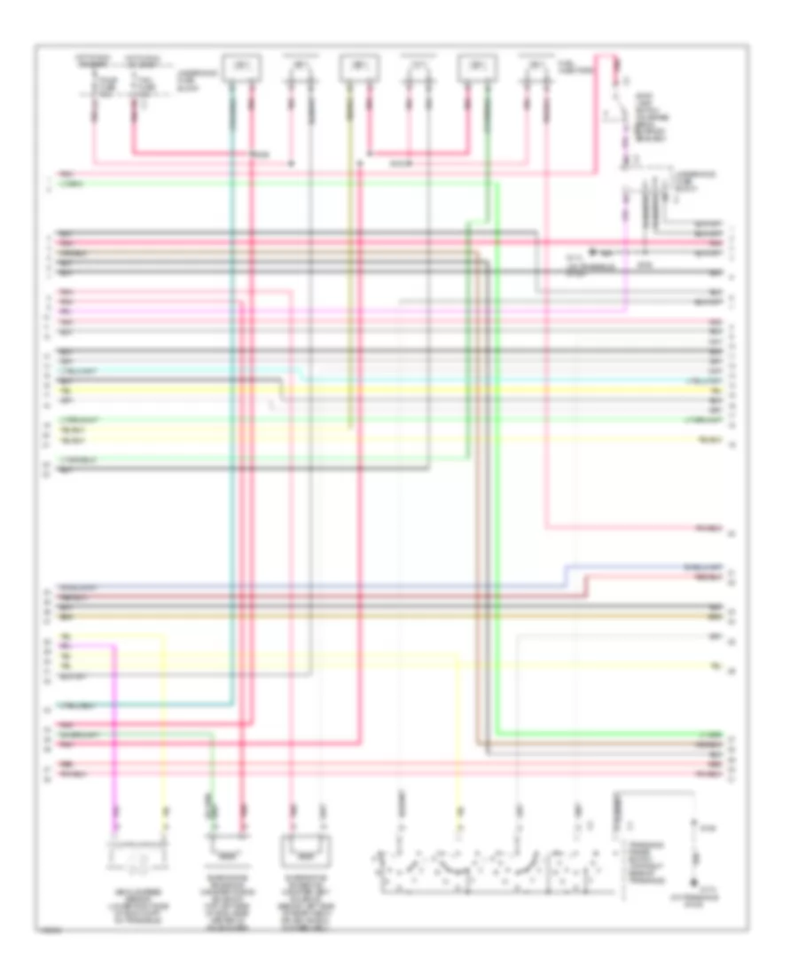
3.5L VIN H, Engine Performance Wiring Diagrams (1 of 4) for Oldsmobile Intrigue GLS 2002
 https://portal-diagnostov.com/license.html
Automotive Electricians Portal FZCO
Automotive Electricians Portal FZCO
https://portal-diagnostov.com/license.html
https://portal-diagnostov.com/license.html
Automotive Electricians Portal FZCO
Automotive Electricians Portal FZCO
List of elements for 3.5L VIN H, Engine Performance Wiring Diagrams (1 of 4) for Oldsmobile Intrigue GLS 2002:
- (engine harn, 13 cm from injector 1 breakout)
- (near left headlamp assembly) secondary air injection pump
- (on trans- axle stud) g129
- (on transaxle stud)
- (pin 11 not used)
- (pin 14-15 not used)
- (pin 2-3 not used)
- (pin 21 & 24-27 not used)
- (pin 39-42 not used)
- (pin 66-67 not used)
- (top of right valve cover)
- 1-2 ss valve control
- 2-3 ss valve control
- A/t iss sensor high
- A/t iss sensor low
- Air pump fuse 50a
- Air pump relay
- Air sol vlv ctrl
- Anti-lock brake system
- B red
- Camshaft position sensor (right front corner of engine)
- Ckp sens a
- Ckp sens b
- Cmp sens sig
- Connector (under left side of dash, right of steering column)
- Cooling fans system
- Cruise control system
- Cruise disable output
- Data link
- Ect sensor signal
- Egr pintle sensor gnd
- Egr val control (gnd)
- Eng emis fuse 10a
- Evap purge val drviver
- Fuel inj 1 driver
- Fuel inj 2 driver
- Fuel inj 4 driver
- Fuel inj 5 driver
- Fuel inj 6 driver
- G113
- G117
- High speed fans control
- Hot at all times
- Hot in off, run bulb test, or start
- Hot in run or start
- I/p fuse block
- Iac coil b high
- Iat sensor ground
- Ig ctrl 1
- Ig ctrl 2
- Ig ctrl 3
- Ig ctrl 4
- Ig ctrl 5
- Ig ctrl 6
- Ign 0 cluster fuse 10a
- Ignition coil bank 1
- Ignition coil bank 2
- Ignition control module bank 1
- Ignition control module bank 2 (top of left valve cover)
- Ignition wake up power
- Knock sensor (next to oil pressure switch)
- Knock sensor signal 2
- Low speed fans control
- Maf sensor signal
- Map sens 5v ref
- Map sensor signal
- Pcm fuse 10a
- Pcm ground
- Pnk
- Pnk f
- Power (battery)
- Powertrain control module (left front side of eng compt, in air cleaner assembly)
- Red
- Ref low
- S106
- S108
- S171
- S270
- Secondary air injection solenoid (bolted to rear engine mount)
- Sensor ground
- Serial data (class 2)
- Spark plugs
- Splice pack sp250 (right side of steering column)
- Tcc brake switch input
- Tft sensor gnd
- Tp sensor signal
- Tr switch input b
- Trans fluid press sw a
- Underhood accessory fuse block
- Underhood fuse block
- Vcc torque req
- Vss high
- Vss low
- Vss output
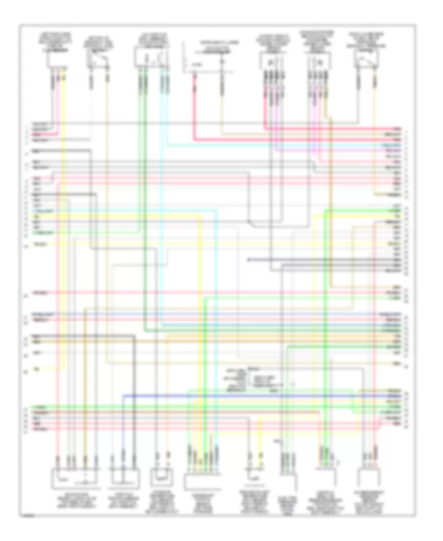
3.5L VIN H, Engine Performance Wiring Diagrams (2 of 4) for Oldsmobile Intrigue GLS 2002
 https://portal-diagnostov.com/license.html
Automotive Electricians Portal FZCO
Automotive Electricians Portal FZCO
https://portal-diagnostov.com/license.html
https://portal-diagnostov.com/license.html
Automotive Electricians Portal FZCO
Automotive Electricians Portal FZCOList of elements for 3.5L VIN H, Engine Performance Wiring Diagrams (2 of 4) for Oldsmobile Intrigue GLS 2002:
- (on transaxle stud)
- Evaporative emissions canister purge solenoid (top left side of eng, near center of valve cover)
- Evaporative emissions canister vent solenoid (behind left side of rear fascia splash shield, in wheelwell)
- F/inj fuse 15a
- F/injr fuse 15a
- Fuel injectors
- G113
- Hot in run or start
- Pnk
- Red
- S106
- S109
- S169
- Stop- lamp switch (on brake pedal support c2 bracket)
- Transaxle range switch (top right rear of transaxle)
- Underhood fuse block
- Vehicle speed sensor (lower right side of eng compt, on transaxle)
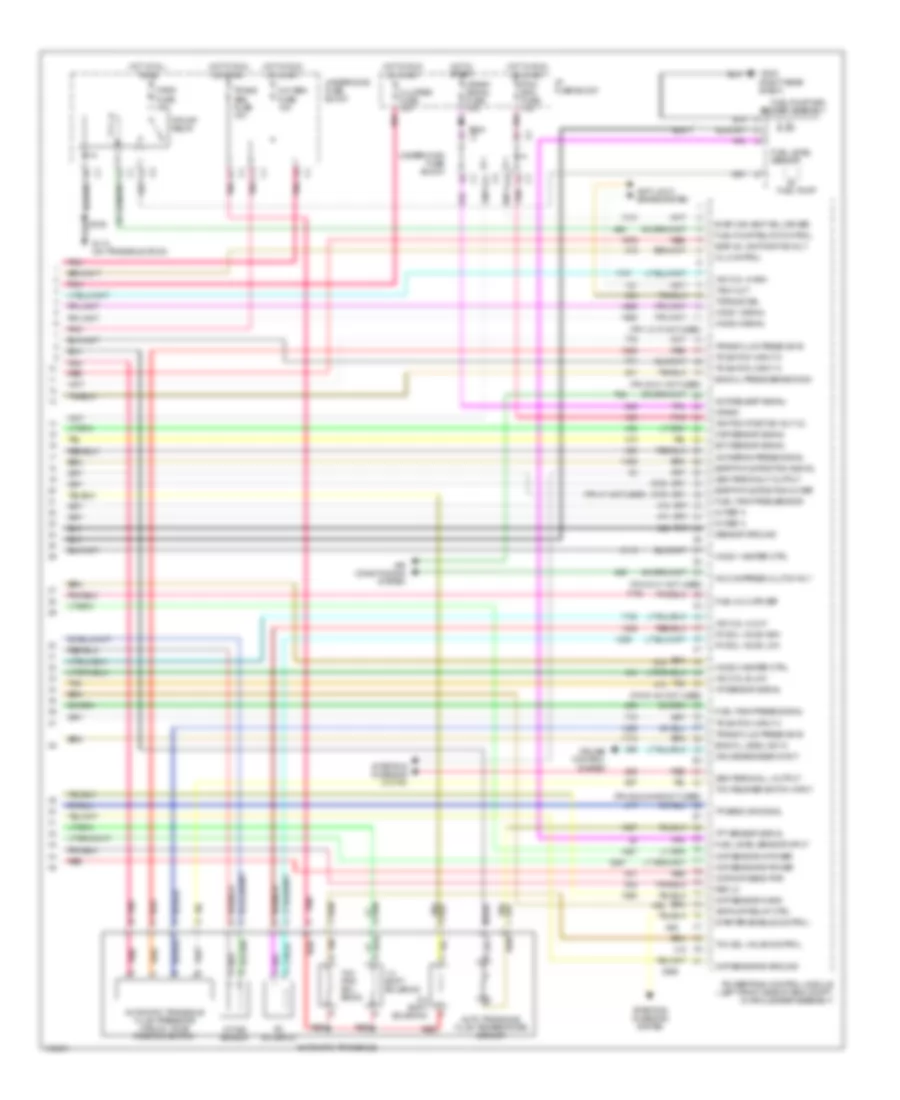
3.5L VIN H, Engine Performance Wiring Diagrams (3 of 4) for Oldsmobile Intrigue GLS 2002
 https://portal-diagnostov.com/license.html
Automotive Electricians Portal FZCO
Automotive Electricians Portal FZCO
https://portal-diagnostov.com/license.html
https://portal-diagnostov.com/license.html
Automotive Electricians Portal FZCO
Automotive Electricians Portal FZCOList of elements for 3.5L VIN H, Engine Performance Wiring Diagrams (3 of 4) for Oldsmobile Intrigue GLS 2002:
- (body harn, front of rear compt)
- (bottom of engine oil pan) engine oil level switch
- (eng harn, near air cleaner, 16 cm from pcm breakout)
- (in exhaust system, behind catalytic converter) heated oxygen sensor (ho2s) 2
- (in right side of exhaust manifold) heated oxygen sensor (ho2s) 1
- (left front side of eng compt, on air cleaner duct) mass air- flow sensor
- (on throttle body assembly) idle air control (iac) valve
- (right lower rear of eng, above transaxle) engine oil pressure switch
- A/c refrigerant pressure sensor (on left side of eng compt, on accumulator)
- Crankshaft position sensor (left side of engine)
- D pnk
- Engine coolant temperature (ect) sensor (right rear of eng, below throttle body)
- Exhaust gas recirculation valve (top rear of eng, near throttle body)
- Fuel tank pressure sensor (in fuel tank)
- Instrument cluster
- Intake air temperature (iat) sensor (left rear of eng compt, in air cleaner duct)
- Logic
- Malfunction indicator lamp
- Manifold absolute pressure sensor (top right of eng, near throttle body assembly)
- Nca
- Pnk
- Red
- S122
- S409
- Tan
- Throttle position sensor (on throttle body assembly)
3.5L VIN H, Engine Performance Wiring Diagrams (4 of 4) for Oldsmobile Intrigue GLS 2002
 https://portal-diagnostov.com/license.html
Automotive Electricians Portal FZCO
Automotive Electricians Portal FZCO
https://portal-diagnostov.com/license.html
https://portal-diagnostov.com/license.html
Automotive Electricians Portal FZCO
Automotive Electricians Portal FZCOList of elements for 3.5L VIN H, Engine Performance Wiring Diagrams (4 of 4) for Oldsmobile Intrigue GLS 2002:
- (pin 12-15 not used)
- (pin 20-21 not used)
- (pin 31 not used)
- (pin 40-41 not used)
- (pin 51-54 not used)
- (pin 62 & 64-65 not used)
- (right rear shelf)
- 1-2 shift solenoid
- 2-3 shift solenoid
- 5v ref a
- A/c compress clutch rly
- A/c refrig press signal
- A/c request signal
- A/t iss sensor
- A11
- Air conditioning system
- Air pump relay ctrl
- Anti-lock brake system
- Auto transaxle fluid temperature sensor
- Automatic transaxle
- Automatic transaxle fluid pressure manual valve position switch
- Ckp sensor a gnd
- Ckp sensor a power
- Ckp sensor b ground
- Ckp sensor b power
- Ckp/cmp sens pwr
- Cluster fuse 10a
- Crank
- Crank signal fuse 10a
- Cruise control system
- Cruise engaged input
- D10
- Ect sensor signal
- Egr pintle position 5v ref
- Egr pintle position signal
- Egr val ign positive volt
- Eng oil level ind in
- Eng oil press sensor sig
- Evap can vent sol driver
- F/pmp fuse 15a
- F/pump relay
- Fuel inj 3 driver
- Fuel level sensor
- Fuel level sensor input
- Fuel pump
- Fuel pump and sender assembly
- Fuel pump relay control
- Fuel tank pres sensor
- Fuel tank press signal
- G113 (on transaxle stud)
- G302
- Gen terminal f output
- Gen terminal l output
- Ho2s 1 heater ctrl
- Ho2s 1 signal
- Ho2s 2 heater ctrl
- Ho2s 2 signal
- Hot at all times
- Hot in run or start
- Hot in start
- I/p fuse block
- Iac coil a high
- Iac coil a low
- Iac coil b low
- Iat sensor signal
- Ignition positive volt (2)
- Map sensor signal
- Mil control
- Oxy sen fuse 15a
- Pc sol valve high
- Pc sol valve low
- Pc solenoid
- Pcm- bcm fuse 10a
- Pnk
- Powertrain control module (left front side of eng compt, in air cleaner assembly)
- Red
- Ref lo
- S106
- S234
- Sensor ground
- Starter enable control
- Starting/ charging system
- Tach out
- Tan
- Tan b
- Tcc pwm sol- enoid
- Tcc release switch input
- Tcc sol valve control
- Tft sensor signal
- Torque del
- Tp sens or signal
- Tr switch input a
- Tr switch input c
- Tr switch input d
- Trans abs fuse 10a
- Trans fluid press sw b
- Underhood fuse block

 Čeština
 Dansk
Dansk Deutsch
 Ελληνικά
 English
 English
 Español
 Suomi
Suomi Français
 Français
 עברית
עברית Hrvatski
 Magyar
 Italiano
 한국어
한국어 Nederlands
 Polski
 Português
 Português
 Română
 Русский
 Slovenčina
 Slovenščina
 Svenska
 Türkçe
 中文 (中国)
