GROUND DISTRIBUTION
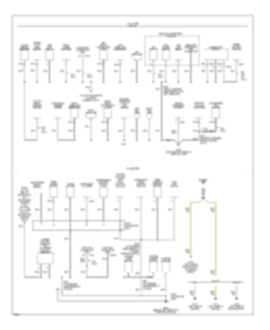
Ground Distribution Wiring Diagram (1 of 4) for Ford Probe GT 1997
 https://portal-diagnostov.com/license.html
Automotive Electricians Portal FZCO
Automotive Electricians Portal FZCO
https://portal-diagnostov.com/license.html
https://portal-diagnostov.com/license.html
Automotive Electricians Portal FZCO
Automotive Electricians Portal FZCO
List of elements for Ground Distribution Wiring Diagram (1 of 4) for Ford Probe GT 1997:
- (front harness, near safety wall grommet) s106
- 2.0l w/o abs & w/ speed control
- A/c high pressure cutout/ fan switch
- A/c relay
- A/t
- Air bag diagnostic monitor
- Brake fluid level switch
- C135
- C209
- C225
- C227
- Clock- spring assembly
- Combination switch
- Diagnostic connector (dlc)
- Electric cooling fan motor
- Engine compartment fuse box
- Fog lamp relay
- G106 (left front of vehicle, near fog lamp)
- Headlamp retractor test connector
- Joint connector c103
- Left fog lamp
- Left front combination lamp
- Left headlamp
- Left headlamp retractor
- M/t
- Nca
- Pcm power relay
- Radio noise capacitor
- Right fog lamp
- Right front combination lamp
- Right headlamp
- Right headlamp retractor
- S105 (front harn, near breakout to right front combination lamp)
- S105 (front harness, near breakout to right front combination lamp)
- S106 (front harness, near safety wall grommet)
- S109 (front harness, near safety wall grommet)
- S118 (front harn, near safety wall grommet)
- S118 (front harness, near breakout to ground g106)
- S119 (front harn, near breakout to hood switch)
- S119 (front harness, near breakout to hood switch)
- S140 (front harn, near break- out to hood switch)
- S197 (front harness, near safety wall grommet)
- S199 (front harness, near breakout to electric cooling fan motor)
- S204
- S225 (front harn, near safety wall grommet)
- Speed control module
- To joint connector c203/g202 (diagram 2 of 4)
- Windshield washer motor
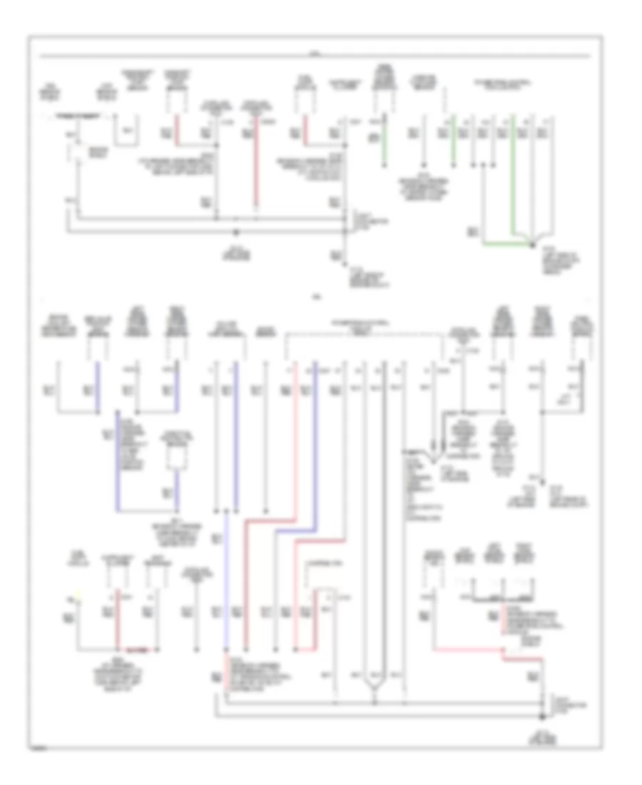
Ground Distribution Wiring Diagram (2 of 4) for Ford Probe GT 1997
 https://portal-diagnostov.com/license.html
Automotive Electricians Portal FZCO
Automotive Electricians Portal FZCO
https://portal-diagnostov.com/license.html
https://portal-diagnostov.com/license.html
Automotive Electricians Portal FZCO
Automotive Electricians Portal FZCOList of elements for Ground Distribution Wiring Diagram (2 of 4) for Ford Probe GT 1997:
- 2.0l
- 2.0l only
- 2.0l w/ abs or 2.5l
- 2.5l a/t
- 2.5l m/t
- 2.5l m/t only
- 2.5l only
- A/c high pressure cutout/ fan switch
- A/c relay
- Abs main relay
- Air bag diagnostic monitor
- All engines
- Battery
- Brake fluid level switch
- C135
- C2020
- C209
- C225
- C227
- C240
- Cigar lighter
- Clock spring assembly
- Clutch pedal position switch
- Combination switch
- Condenser fan motor
- Data link connector (dlc)
- Daytime running lamps (drl) control module
- Diagnostic connector (dlc)
- Electric cooling fan motor
- Engine compartment fuse box
- Ex 2.0l a/t only
- Flasher module
- Fog lamp relay
- Fog lamp switch
- From 2.0l w/o abs: a/t, splice s197; m/t, splice s225 (diagram 1 0f 4) or from 2.0l w/ abs or 2.5l, splice s106 diagram 2 of 4)
- G100 (left side of engine compt, on fender apron)
- G106 (left front of vehicle, near fog lamp)
- G112 (left side of engine)
- G114 (left rear of engine)
- G116 (left rear of engine compt)
- G202 (behind left side of i/p, near drl module)
- Headlamp retractor test connector
- Heater control assembly or a/c-heater control assembly
- Instrument cluster
- Instrument panel dimming module
- Joint connector c203
- Joint connector c234
- Left fog lamp
- Left front combination lamp
- Left headlamp
- Left headlamp retractor
- Liftgate washer switch
- Liftgate wiper switch
- Nca
- Park range switch
- Pcm power relay
- Radio noise capacitor
- Rear window defrost switch
- Right fog lamp
- Right front combination lamp
- Right headlamp
- Right headlamp retractor
- S106 (front harness, near breakout to left headlamp)
- S107
- S207 (i/p harness, near breakout to g202)
- S208 (i/p harness, near breakout to rear defrost switch)
- S211 (emission harness, behind center of i/p)
- S213 (i/p harness, near breakout to g202)
- Speed control module
- Tachometer signal shield
- To joint connector c203/g202 (diagram 2 of 4)
- Transmission control switch (tcs)
- Windshield washer motor
Ground Distribution Wiring Diagram (3 of 4) for Ford Probe GT 1997
 https://portal-diagnostov.com/license.html
Automotive Electricians Portal FZCO
Automotive Electricians Portal FZCO
https://portal-diagnostov.com/license.html
https://portal-diagnostov.com/license.html
Automotive Electricians Portal FZCO
Automotive Electricians Portal FZCOList of elements for Ground Distribution Wiring Diagram (3 of 4) for Ford Probe GT 1997:
- 2.0l
- 2.5l
- 4eat transaxle
- Boost sensor
- C134
- C135
- C2020
- C241
- C247
- C248
- Camshaft position (cmp) sensor
- Ckp sensor shield
- Crankshaft position (ckp) sensor
- Data link connector (dlc)
- Distributor
- Egr valve position (evp) sensor
- Engine coolant temperature (ect) sensor
- Engine shield
- Fuel pump module
- G100 (left side of engine compt, on fender apron)
- G112 (a/t) (left side of engine)
- G112 (left side of engine)
- G112 (left side of engine, on engine mount)
- G116 (m/t) (left rear of engine compt)
- Instrument cluster
- Joint connector c106
- Knock sensor (ks)
- Left ho2s sensor shield
- Left rear heated oxygen sensor (ho2s) #21
- M/t only
- Mass air flow (maf) sensor
- Nca
- Park/ neutral position switch
- Powertrain control module (pcm)
- Rear heated oxygen sensor (ho2s) #12
- Right ho2s sensor shield
- Right rear heated oxygen sensor (ho2s) #11
- S1000 (emission harness, near breakout to powertrain control module)
- S104 (emission harness, near breakout to distributor)
- S110 (engine harness, near breakout to: a/t, ground g112; mt, ground g116)
- S123 (emission harness, near breakout to: a/t, transaxle control solenoid valve; m/t, distributor)
- S126 (emiss- ion harness, near breakout to: a/t, ground g112; m/t, distributor)
- S136 (emission harness, near breakout to: a/t, g112; m/t, ignition coil module (icm))
- S138 (emission harness, near breakout to heated oxygen sensor ho2s)
- S195 (engine harness, near breakout to egr valve position sensor)
- S211 (emission harness, near breakout to c249, behind center of i/p)
- S228 (i/p harness, near breakout to joint connector c269, behind left side of i/p)
- Throttle position (tp) sensor
- Tss sensor shield
- Volume air flow (vaf) sensor
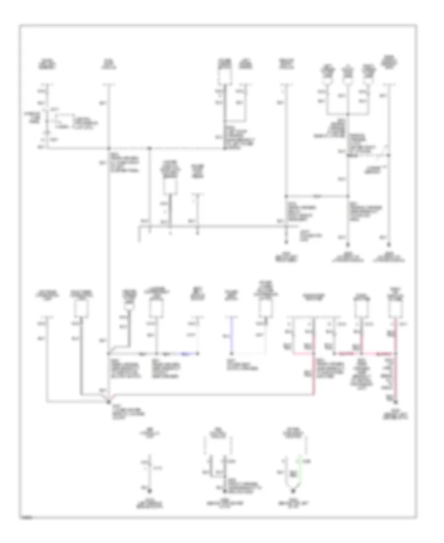
Ground Distribution Wiring Diagram (4 of 4) for Ford Probe GT 1997
 https://portal-diagnostov.com/license.html
Automotive Electricians Portal FZCO
Automotive Electricians Portal FZCO
https://portal-diagnostov.com/license.html
https://portal-diagnostov.com/license.html
Automotive Electricians Portal FZCO
Automotive Electricians Portal FZCOList of elements for Ground Distribution Wiring Diagram (4 of 4) for Ford Probe GT 1997:
- (rear #2 harness, in top center front of liftgate) s402
- Abs control module
- Abs hydraulic unit
- Air bag diagnostic monitor
- C173
- C201
- C209
- C211
- C213
- C217
- C222
- C315
- C318
- Center license plate lamp
- Central processing unit (cpu)
- Dome/ map lamp assembly
- Fuel pump module
- G102 (left rear of engine compt)
- G202 (behind top left of i/p)
- G206 (behind left center of i/p)
- G206 (behind top center of i/p)
- G300 (below left front seat)
- G407 (lower center rear of luggage compt)
- G909 (in front of liftgate window)
- Hi mount stop lamp
- Interior fuse panel
- Joint connector c300
- Left license plate lamp
- Left power mirror
- Left rear combination lamp
- Luggage compartment lamp switch
- Master window/ door lock control switch
- Nca
- Power door lock relay
- Power lumbar/ bolster compressor motor
- Power mirror switch
- Power seat switch
- Radio amplifier
- Radio or radio/cd player
- Rear window defrost grid
- Remote entry module
- Right license plate lamp
- Right rear combination lamp
- S200 (i/p harn, in break- out to radio)
- S203 (front harness, near breakout to ground g206)
- S300 (rear harness, near breakout to central processing unit)
- S301 (rear harness, near breakout to right rear speaker)
- S302 (rear harness, in lower front of left quarter panel)
- S303 (rear harness, near breakout to subwoofer amplifier)
- S307 (power seat switch harness)
- S315 (rear harness, below right side of rear seat)
- S400 (rear harness, near breakout to inertia fuel shutoff switch)
- S401 (rear #3 harness, near breakout to ground g909)
- S403 (rear #2 harness, in center rear of liftgate)
- S500 (left door harness, near breakout to left power mirror)
- Seat belt buckle switch
- Subwoofer amplifier
- W/ rear defrost

 Čeština
 Dansk
Dansk Deutsch
 Ελληνικά
 English
 English
 Español
 Suomi
Suomi Français
 Français
 עברית
עברית Hrvatski
 Magyar
 Italiano
 한국어
한국어 Nederlands
 Polski
 Português
 Português
 Română
 Русский
 Slovenčina
 Slovenščina
 Svenska
 Türkçe
 中文 (中国)
