POWER DISTRIBUTION
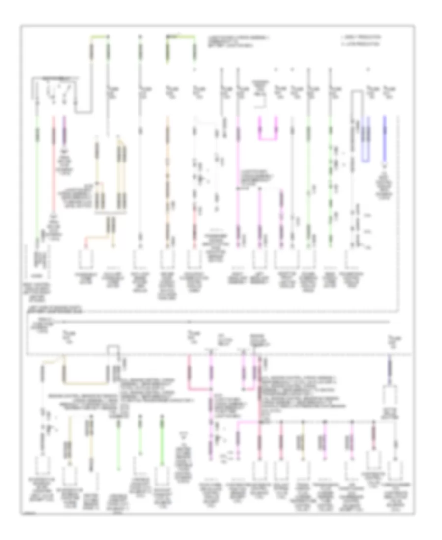
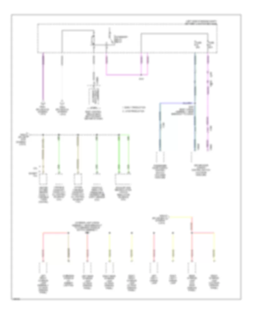
Power Distribution Wiring Diagram (1 of 6) for Ford Escape S 2014
 https://portal-diagnostov.com/license.html
Automotive Electricians Portal FZCO
Automotive Electricians Portal FZCO
https://portal-diagnostov.com/license.html
https://portal-diagnostov.com/license.html
Automotive Electricians Portal FZCO
Automotive Electricians Portal FZCO
List of elements for Power Distribution Wiring Diagram (1 of 6) for Ford Escape S 2014:
- (2.0l: engine control wiring assembly, near breakout to coil on plug (cop) 2) (1.6l: engine control sensor extension wiring assembly, near breakout to coil on plug (cop) 2)
- (diagram 3 of 6)
- (diagram 4 of 6)
- (engine control wiring assembly, near breakout to fuel (2.0l) s116 (1.6l) s122
- (junction box wiring assembly, in breakout to bjb) s144
- (left side of engine compt) battery junction box (bjb)
- (left side of engine compt) high current battery junction box (bjb)
- (right kick panel) g206
- 1.6l
- 2.0l
- 2.5l
- A/c clutch relay
- Anti-lock brake system (abs) module
- Auxiliary power point
- Battery
- Battery junction box (bjb) (left side of engine compt)
- Battery monitoring sensor
- Blower motor relay
- Body control module (bcm) (bottom right center of dash)
- Body control module (bcm) (early production)
- Brake pedal position (bpp) switch
- C1035a
- C1035b
- C1035c
- C1381b
- C1463a
- C1551b
- C1617a
- C1617b
- C1617c
- C1617d
- C1617e
- C1617f
- C1617g
- C1617h
- C1617j
- C1617l
- C175b
- C197a
- C210
- C211
- C212
- C219
- C22800
- C2280g
- C2603a
- C3053
- C328
- C339
- Early
- Electric booster heater
- Engine cooling fan relay
- Evaporative emission canister vent solenoid (2.5l)
- Except 2.0l
- Except 2.5l
- Front power outlet socket
- Fuel pump relay
- Fuse 10a
- Fuse 15a
- Fuse 20a
- Fuse 30a
- Fuse 40a
- Fuse 5a
- G100 (left rear of engine compt)
- Generator
- Headlamp switch
- Horn relay
- Ignition coil on-plugs
- Injector 3) (2.5l) s113
- Keyless entry keypad
- Late production
- Liftgate/ decklid release relay
- Mega fuse 1 80a
- Mega fuse 2 150a
- Mega fuse 3 100a
- Mega fuse 4 50a
- Mega fuse 6 70a
- Mega fuse 60a
- Mega fuse 8 50a
- Mega fuse 80a
- Mega fuse 9 50a
- Micro
- Noise suppression capacitor (2.5l)
- Pcm power relay
- Power steering control module (pscm)
- Powertrain control module (pcm)
- Production
- Rear passenger power outlet socket
- Rear window defrost relay
- Red
- Red (battery cable wiring assembly, near breakout to generator) s155
- S131 (1.6l) s103 (2.0l) s112 (2.5l) (1.6l: engine control sensor extension wiring assembly, near breakout to c1019) (2.0l: engine control wiring assembly, in breakout to battery junction box (bjb)) (2.5l: engine control wiring assembly, in breakout to powertrain control module (pcm))
- S151 (power steering wiring assembly, near breakout to g108)
- S329
- Starter motor
- Starter relay
- To battery junction box (bjb) (diagram 2 of 6)
- To battery junction box (bjb) (diagram 6 of 6)
- To fuse 33 (diagram 2 of 6)
- To fuse 70
- To fuse 74
- To rear junction box (rjb) (diagram 5 of 6)
- To splice s401 (diagram 5 of 6)
- V batt
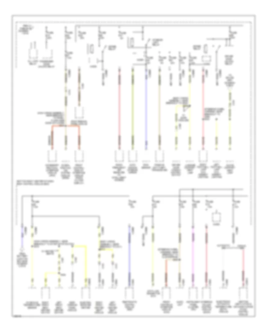
Power Distribution Wiring Diagram (2 of 6) for Ford Escape S 2014
 https://portal-diagnostov.com/license.html
Automotive Electricians Portal FZCO
Automotive Electricians Portal FZCO
https://portal-diagnostov.com/license.html
https://portal-diagnostov.com/license.html
Automotive Electricians Portal FZCO
Automotive Electricians Portal FZCOList of elements for Power Distribution Wiring Diagram (2 of 6) for Ford Escape S 2014:
- (2.0l: engine control wiring assembly, near breakout to coil on plug (cop) 4) (2.5l: engine control wiring assembly, near breakout to ignition transformer capacitor 1) (2.0l) s119 (2.5l) s100
- (canada) front fog relay
- (engine control sensor extension wiring assembly, near breakout to engine coolant temperature (ect) sensor) (1.6l) s128
- (junction box wiring assembly, in breakout to battery junction box)
- (junction box wiring assembly, near breakout to g105) s140
- (left side of engine compt) battery junction box (bjb)
- (not used)
- 1.6l
- 2.0l
- 2.5l
- A/c clutch relay
- A13
- Active grille shutter
- Adaptive front lighting module
- Air conditioning (a/c) compressor control solenoid (except 2.5l)
- Anti-lock brake system (abs) module
- Auxiliary windshield wiper motor
- Body control module (bcm) (bottom right center of dash)
- C1021a
- C1035c
- C1041a
- C133
- C1381b
- C1463b
- C1551b
- C175b
- C210
- C212
- C2280d
- C3053
- C312
- C339
- C410
- C438
- C504a
- Control relay ignition
- Coolant bypass valve (1.6l)
- Driver door window control switch (w/o door modules)
- Early production
- Engine cooling fan relay
- Evaporative emission (evap) canister vent valve (except 2.5l)
- Evaporative emission canister purge valve
- Exhaust camshaft (vct) oil solenoid (1.6l)
- Four wheel drive (4wd) control module (except 2.5l)
- From fuse 35 g (diagram 1 of 6)
- From splice s144 (diagram 1 of 6)
- From splice s145 (diagram 1 of 6)
- Fuse 10a
- Fuse 15a
- Fuse 20a
- Fuse 50a
- Fuse 5a
- Heated oxygen sensor (ho2s) 12
- Ignition relay
- Late production
- Left headlamp assembly
- Micro
- Nca
- Near breakout to brake fluid level switch)
- Occupant classification system module (ocsm)
- Passenger air bag deactivation (pad) indicator/ defrost switch
- Power steering control module (pscm)
- Powertrain control module (pcm)
- Rear window wiper motor
- Right headlamp assembly
- S143
- S147 (junction box wiring assembly, near breakout to battery junction box)
- To body control module (bcm) (diagram 3 of 6)
- To heated oxygen sensor (ho2s) 11 variable timing control (diagram 6 of 6)
- Trans- mission fluid warmer temperature control valve 1
- Transmission fluid warmer tempera- ture control valve 2
- Turbocharger (tc) wastegate regulating valve solenoid (2.0l)
- Variable camshaft timing (vct) solenoid 11 (2.0l)
- Variable camshaft timing (vct) solenoid 12 (2.0l)
- Wastegate control solenoid (1.6l)
- Wastegate control valve (1.6l)
- Wastegate position sensor (except 2.5l)
- Windshield wiper motor
Power Distribution Wiring Diagram (3 of 6) for Ford Escape S 2014
 https://portal-diagnostov.com/license.html
Automotive Electricians Portal FZCO
Automotive Electricians Portal FZCO
https://portal-diagnostov.com/license.html
https://portal-diagnostov.com/license.html
Automotive Electricians Portal FZCO
Automotive Electricians Portal FZCOList of elements for Power Distribution Wiring Diagram (3 of 6) for Ford Escape S 2014:
- (body wiring assembly, near breakout to c311) s314
- (body wiring assembly, near breakout to g200) s206
- (bottom right center of dash) body control module (bcm)
- (main wiring assembly, near breakout to panel/ floor mode door actuator) s214
- (main wiring assembly, near breakout to start/stop switch) s218
- (not used)
- (steering wheel harness, near breakout to c260) s244
- (steering wheel harness, near breakout to clockspring) s235
- Accessory protocol interface module (apim)
- All lock relay
- Audio unit
- Auto- dimming interior mirror
- Automatic a/c
- C214
- C215
- C226a
- C2280d
- C2280e
- C2280f
- C2280h
- C228b
- C2357a
- C240a
- C248
- C2603c
- C310a
- C311
- C312
- C327
- C329a
- C339
- C359a
- Data link connector (dlc)
- Driver door unlock relay
- Driver door window control switch
- Electric booster heater
- Electronic automatic temperature (eatc) module
- From battery junction box (bjb) (diagram 2 of 6)
- From fuse 65 c (diagram 1 of 6)
- Front control/ display interface module (fcdim) (4.2 inch display)
- Front controls interface module (fcim)
- Fuse 10a
- Fuse 15a
- Fuse 20a
- Fuse 25a
- Fuse 5a
- Fuse 7.5a
- Global position- ing system module (gpsm)
- Glove compart- ment lamp
- Heating ventilation & air conditioning (hvac) control module
- In-vehicle temperature/ sensor
- Instrument panel cluster (ipc)
- Interior light relay
- Left footwell lamp (w/o ambient lighting)
- Left front heated seat module
- Left front seat heated switch
- Luggage compart- ment lamp
- Manual a/c
- Micro
- Passenger door unlock relay
- Passive anti-theft transceiver
- Radio frequency (rf) receiver (w/ intelligent access)
- Rain sensor
- Restraints control module (rcm)
- Right footwell lamp (w/o ambient lighting)
- Right front heated seat module
- Right front seat heated switch
- Roof opening panel module
- S328
- Spare relay
- Steering column control module (sccm)
- To splice s901 (diagram 6 of 6)
- W/ door modules
- W/ heated seats
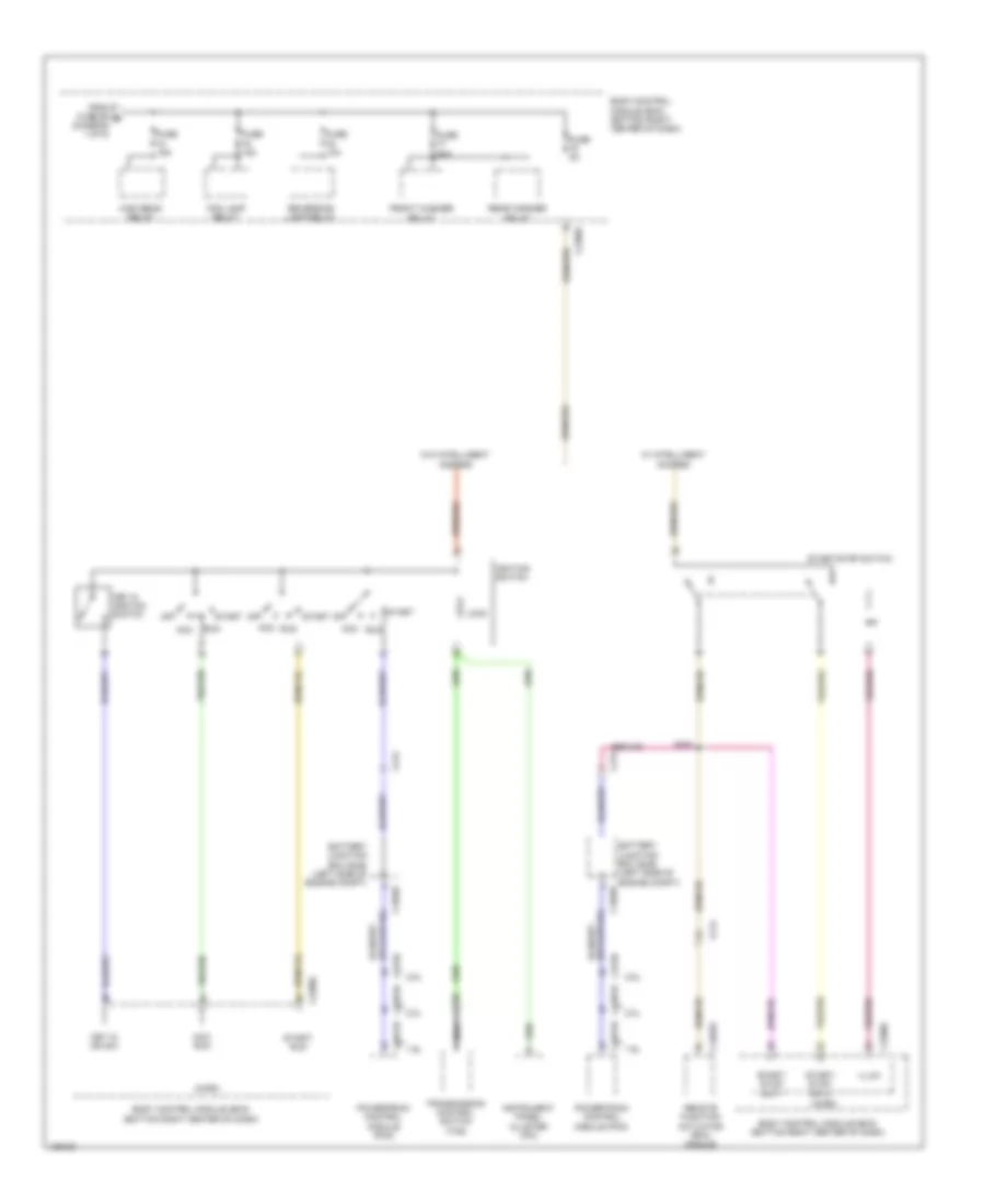
Power Distribution Wiring Diagram (4 of 6) for Ford Escape S 2014
 https://portal-diagnostov.com/license.html
Automotive Electricians Portal FZCO
Automotive Electricians Portal FZCO
https://portal-diagnostov.com/license.html
https://portal-diagnostov.com/license.html
Automotive Electricians Portal FZCO
Automotive Electricians Portal FZCOList of elements for Power Distribution Wiring Diagram (4 of 6) for Ford Escape S 2014:
- 1.6l
- 2.0l
- 2.5l
- Acc
- Acc run
- Acc/ run
- Battery junction box (bjb) (left side of engine compt)
- Body control module (bcm) (bottom right center of dash)
- C1035c
- C1381b
- C1551b
- C175b
- C212
- C214
- C2280c
- C2280f
- C4392d
- Fog lamp relay
- From fuse 56 b (diagram 1 of 6)
- Front washer relay
- Fuse 10a
- Fuse 15a
- Fuse 20a
- Fuse 5a
- High beam relay
- Ignition switch
- Illum
- Instrument panel cluster (ipc)
- Key in ign sw
- Key in ignition switch
- Lock
- Micro
- Nca
- Off
- Powertrain control module (pcm)
- Rear washer relay
- Remote function actuator (rfa) module
- Reversing lamp relay
- Run
- S254
- Start
- Start/ run
- Start/ stop sw 1
- Start/ stop sw 2
- Start/stop switch
- Transmission control switch (tcs)
- W/ intelligent access
- W/o intelligent access
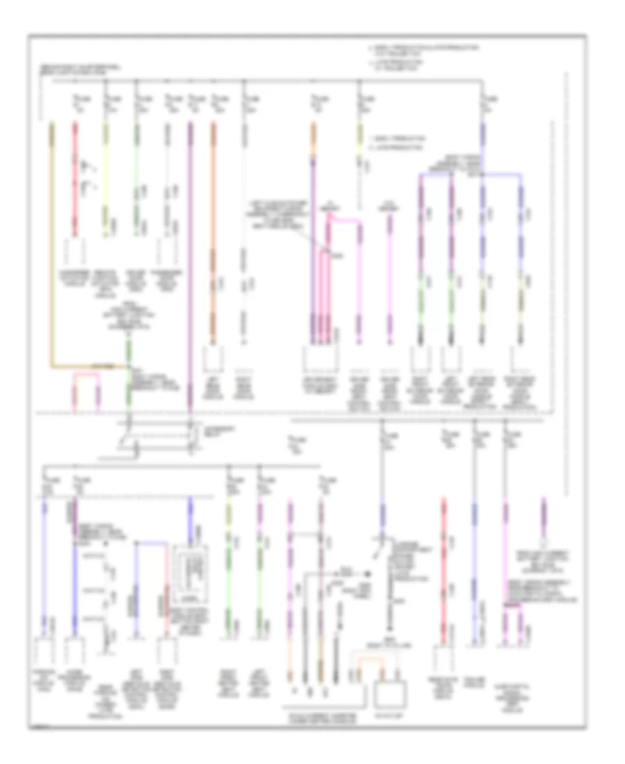
Power Distribution Wiring Diagram (5 of 6) for Ford Escape S 2014
 https://portal-diagnostov.com/license.html
Automotive Electricians Portal FZCO
Automotive Electricians Portal FZCO
https://portal-diagnostov.com/license.html
https://portal-diagnostov.com/license.html
Automotive Electricians Portal FZCO
Automotive Electricians Portal FZCOList of elements for Power Distribution Wiring Diagram (5 of 6) for Ford Escape S 2014:
- (behind right quarterpanel) rear junction box (rjb)
- (body wiring assembly, near breakout to audio digital signal processing (dsp) module) s419
- (body wiring assembly, near breakout to c312) s311
- (body wiring assembly, near breakout to rjb) s403
- (left cushion power equipment wiring assembly, in breakout to driver's seat module (dsm))
- (not used)
- A14
- A17
- Ac outlet
- Acc
- Accessory relay
- Audio digital signal processing (dsp) module
- Body control module (bcm) (bottom right center of dash)
- C214
- C2280b
- C311
- C312
- C313
- C314
- C327
- C328
- C329a
- C339
- C340
- C341d
- C3497a
- C359a
- C4014a
- C410
- C4174a
- C421
- C432
- C4326c
- C438
- C4392c
- C4397a
- C4464
- C501a
- C511
- C611
- C652a
- C710
- C810
- Control relay accessory
- Dc/ac current inverter (under center console)
- Driver door module (ddm)
- Driver seat module (dsm) (w/ memory)
- Driver side front seat control switch
- Early production
- Early production & late production
- From high current battery junction box (bjb) (diagram 1 of 6)
- Fuse 10a
- Fuse 20a
- Fuse 25a
- Fuse 30a
- Fuse 40a
- Fuse 5a
- G206 (right kick panel)
- G400 (right "d" pillar)
- Gnd
- Handsfree actuation module
- Image processing module (ipm-b)
- Late production
- Left front exterior door handle
- Left front heated seat module
- Left rear door module
- Left rear exterior door handle (early production)
- Left side obstacle detection control module (sodl)
- Luggage compartment power outlet socket (late production)
- Micro
- Nca
- Parking aid module (pam)
- Passenger door module (pdm)
- Rear gate trunk module (rgtm)
- Rear parking aid camera (late production)
- Red
- Remote function actuator (rfa) module
- Right front exterior door handle
- Right front heated seat module
- Right rear door module
- Right rear exterior door handle (early production)
- Right side obstacle detection control module (sodr)
- S329
- S330
- S400
- S401 (body wiring assembly, near breakout to rjb)
- Trailer module
- W/ memory
- W/ trailer tow
- W/o memory
- W/o trailer tow
Power Distribution Wiring Diagram (6 of 6) for Ford Escape S 2014
 https://portal-diagnostov.com/license.html
Automotive Electricians Portal FZCO
Automotive Electricians Portal FZCO
https://portal-diagnostov.com/license.html
https://portal-diagnostov.com/license.html
Automotive Electricians Portal FZCO
Automotive Electricians Portal FZCOList of elements for Power Distribution Wiring Diagram (6 of 6) for Ford Escape S 2014:
- (interior lamp wiring assembly, near breakout to overhead console switch assembly) s901
- (left side of engine compt) battery junction box (bjb)
- 2.5l
- A11
- A14
- Accessory
- Accessory delay relay
- Body control module (bcm) (bottom right center of dash)
- C210
- C2280a
- C3053
- C339
- C340
- C504b
- C504c
- Control delay relay
- Driver door window control switch (w/o door modules)
- Early production
- Except 2.5l
- Exhaust gas recirculation vacuum regulator solenoid (2.5l)
- From m splice s100 (diagram 2 of 6)
- From splice s144 (diagram 1 of 6)
- From splice s145 (diagram 1 of 6)
- From splice s244 j (diagram 3 of 6)
- Front interior lamp (w/o roof opening panel)
- Fuse 25a
- Heated oxygen sensor (ho2s) 11 variable timing control
- Intake variable camshaft timing (vct) oil control solenoid (1.6l)
- Late production
- Left front interior lamp assembly (w/ roof opening panel)
- Left rear interior lamp (w/ roof opening panel)
- Left vanity mirror lamp
- Manifold absolute pressure & temperature (mapt) sensor (2.5l)
- Micro
- Overhead console (w/ ambient lighting)
- Passenger door window control switch (w/o door modules)
- Rear interior lamp (w/o roof opening panel)
- Right front interior lamp (w/ roof opening panel)
- Right rear interior lamp (w/ roof opening panel)
- Right vanity mirror lamp
- S181
- S300 (body wiring assembly, near breakout to c340a)
- Variable camshaft timing (vct) oil control solenoid (2.5l)

 Čeština
 Dansk
Dansk Deutsch
 Ελληνικά
 English
 English
 Español
 Suomi
Suomi Français
 Français
 עברית
עברית Hrvatski
 Magyar
 Italiano
 한국어
한국어 Nederlands
 Polski
 Português
 Português
 Română
 Русский
 Slovenčina
 Slovenščina
 Svenska
 Türkçe
 中文 (中国)
