RADIO
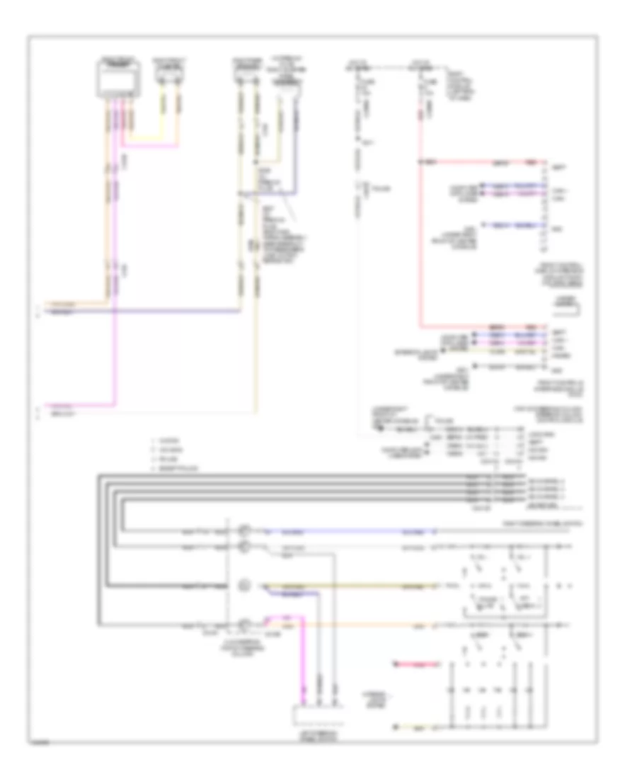
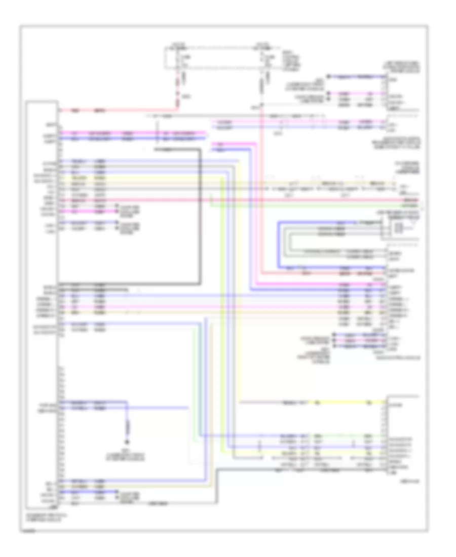
Premium Radio Wiring Diagram (1 of 2) for Ford Explorer XLT 2014
 https://portal-diagnostov.com/license.html
Automotive Electricians Portal FZCO
Automotive Electricians Portal FZCO
https://portal-diagnostov.com/license.html
https://portal-diagnostov.com/license.html
Automotive Electricians Portal FZCO
Automotive Electricians Portal FZCO
List of elements for Premium Radio Wiring Diagram (1 of 2) for Ford Explorer XLT 2014:
- (body main wiring assembly, near breakout to driver's safety belt retractor pretensioner) (w/ premium plus) s323
- (center rear of roof) antenna module
- (w/ premium plus) left quarter panel speaker
- (w/ satellite radio)
- (w/ sync) s212
- (w/o sync) audio input jack
- Accessory protocol interface module
- Alert+
- Alert-
- Am/fm
- Antenna pwr
- Audio control module (acm)
- Batt
- Body control module (left end of dash)
- C2026
- C210
- C211
- C2280a
- C237
- C240a
- C240b
- C3138
- C327
- Ce336
- Coaxial cable
- Computer data lines system
- Dme45
- Dme52
- Dme80
- Fuse 20a
- G201 (under right front of center console)
- Gd214
- Global positioning system module (left side of dash)
- Gnd
- Hot at all times
- I can +
- I can -
- Instrument panel speaker
- Ip spkr +
- Ip spkr -
- Left front speaker
- Left front tweeter
- Left rear speaker
- Lf spkr +
- Lf spkr -
- Lr spkr +
- Lr spkr -
- Ms can +
- Ms can -
- Nca
- Police
- Rf spkr +
- Rf spkr -
- Rme06
- Rme07
- Rme09
- Rme10
- Rme12
- Rme46
- Rme52
- Rme53
- Rme80
- Rr spkr +
- Rr spkr -
- S322 (w/ premium plus) (body main wiring assembly, near breakout to driver's safety belt retractor pretensioner)
- Sbp29
- Sdars
- Sdl h
- Sdl l
- Shield
- St input 2l+
- St input 2r+
- St input 2r-
- Start
- Starting/ charging system
- State solid
- Stereo 2l+
- Stereo 2r+
- Stereo 2r-
- Stereo l +
- Stereo l -
- Stereo r +
- Stereo r -
- Stereo shield
- Vbatt
- Vdb06
- Vdb07
- Vdb13
- Vdb14
- Vme06
- Vme07
- Vme09
- Vme10
- Vme12
- Vme43
- Vme45
- Vme46
- Vme52
- Vme53
- Vme80
- Vme90
- Vme91
- W/ sync gen 1
- W/ sync gen 2
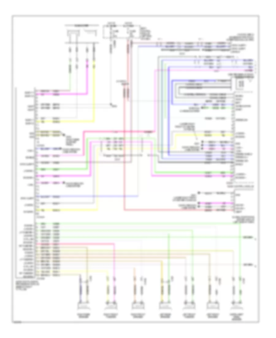
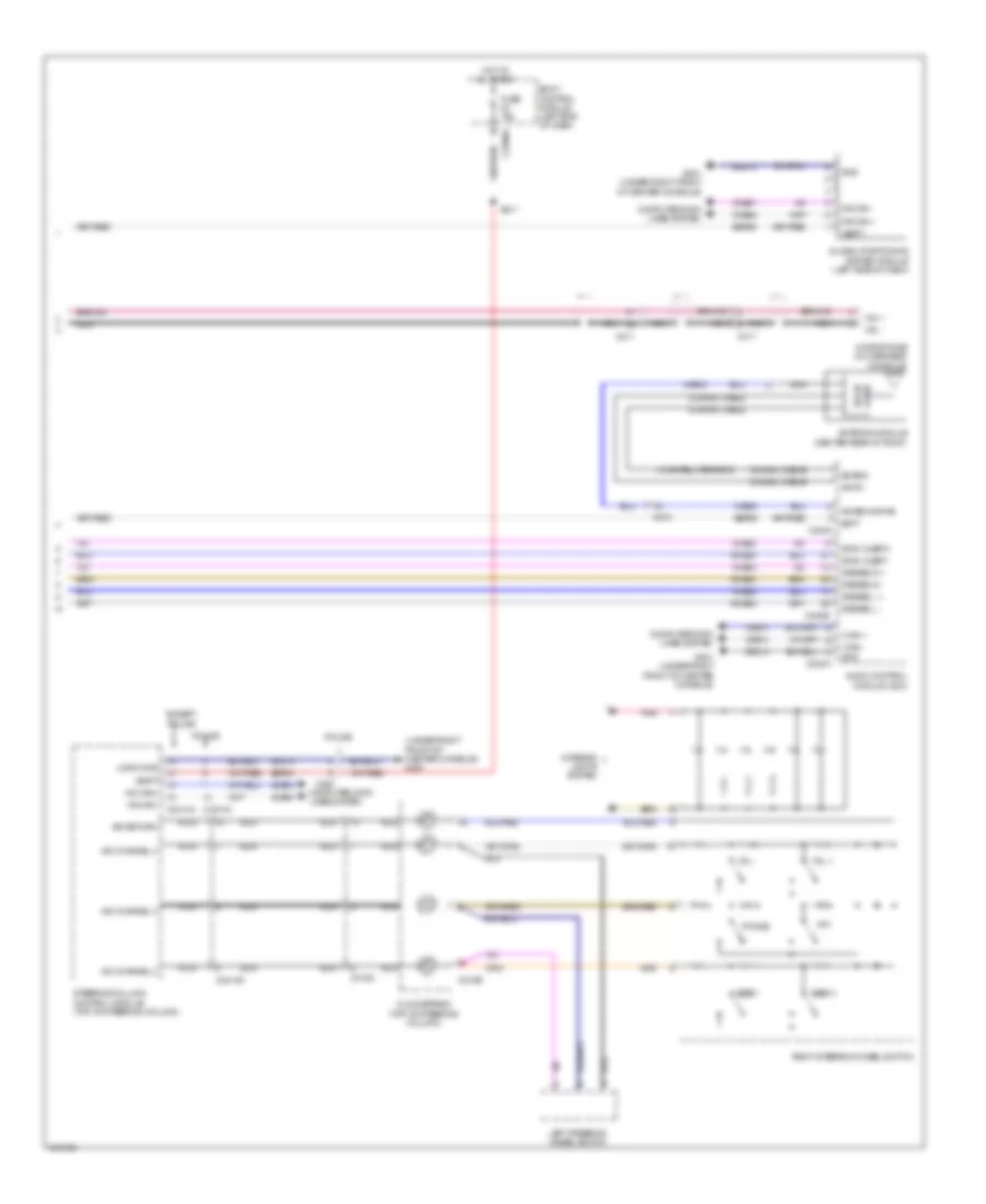
Premium Radio Wiring Diagram (2 of 2) for Ford Explorer XLT 2014
 https://portal-diagnostov.com/license.html
Automotive Electricians Portal FZCO
Automotive Electricians Portal FZCO
https://portal-diagnostov.com/license.html
https://portal-diagnostov.com/license.html
Automotive Electricians Portal FZCO
Automotive Electricians Portal FZCOList of elements for Premium Radio Wiring Diagram (2 of 2) for Ford Explorer XLT 2014:
- (top of steering column) steering column control module
- (under right front of center console) g201
- (w/ premium plus) right quarter panel speaker
- A/d channel 2
- A/d channel 3
- A/d channel 4
- A/d return
- Body control module (left end of dash)
- C210
- C218b
- C218c
- C2280a
- C2280b
- C2414a
- C2414d
- C263
- C3139
- C316
- Clockspring (top of steering column)
- Cls32
- Computer data lines system
- Except police
- Exterior lights system
- Front control/ display interface module (fcdim) (w/o sync gen2)
- Front controls interface module (fcim)
- Fuse 10a
- Fuse 15a
- G201 (under right front of center console)
- Gd214
- Gnd
- Hazard
- Hazard switch
- Hot at all times
- Hs can+
- Hs can-
- I can +
- I can -
- Interior lights system
- Left steering wheel switch
- Logic gnd
- Media
- Mute
- Nca
- Phone
- Pnk
- Police
- Ptt
- Red
- Right front speaker
- Right front tweeter
- Right rear speaker
- Right steering wheel switch
- S203
- S211
- S326 (w/ premium plus)
- S327 (w/ premium plus) (body main wiring assembly, near breakout to passenger's load limiting retractor)
- Sbp09
- Sbp23
- Seek +
- Seek -
- Vbatt
- Vdb04
- Vdb05
- Vdb13
- Vdb14
- Vol +
- Vol -
- W/ sync
- W/o sync
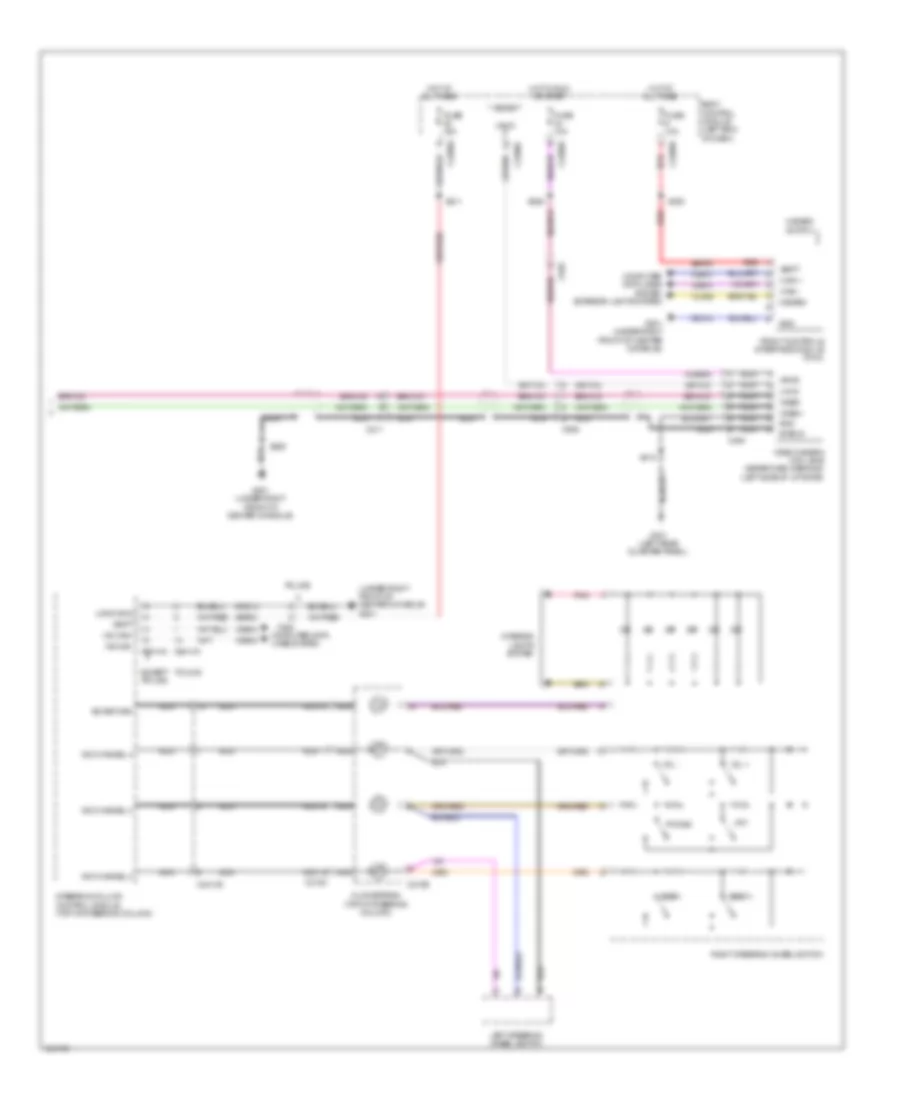
SONY Radio Wiring Diagram (1 of 2) for Ford Explorer XLT 2014
 https://portal-diagnostov.com/license.html
Automotive Electricians Portal FZCO
Automotive Electricians Portal FZCO
https://portal-diagnostov.com/license.html
https://portal-diagnostov.com/license.html
Automotive Electricians Portal FZCO
Automotive Electricians Portal FZCOList of elements for SONY Radio Wiring Diagram (1 of 2) for Ford Explorer XLT 2014:
- (center rear of roof) antenna module
- (under right front of center console)
- (w/ satellite radio)
- (w/ sync gen 2) accessory protocol interface module (apim)
- (w/ sync) s212
- Am/fm
- Antenna pwr
- Audio control module
- Audio digital signal processing module (base of right "c" pillar)
- Batt
- Body control module (left end of dash)
- C210
- C2280a
- C2280d
- C237
- C240a
- C3138
- C3139
- C3154a
- C3154b
- C3154c
- C316
- C327
- Ce336
- Coaxial cable
- Computer data lines system
- D pillar -
- D pillar+
- Dme17
- Dme45
- Dme80
- Enable
- Fuse 20a
- G201
- G201 (under right front of center console)
- G302 (right rear quarter panel)
- Gd214
- Gd348
- Global positioning system module (left side of dash)
- Gnd
- Hot at all times
- I can +
- I can -
- Instrument panel speaker
- Ip spkr +
- Ip spkr -
- Left front speaker
- Left front tweeter
- Left rear speaker
- Lf spkr +
- Lf spkr -
- Lf tweeter +
- Lf tweeter -
- Lr spkr +
- Lr spkr -
- Ms can +
- Ms can -
- Nca
- Rf spkr +
- Rf spkr -
- Rf tweeter +
- Rf tweeter -
- Right front speaker
- Right front tweeter
- Right rear speaker
- Rme01
- Rme02
- Rme06
- Rme07
- Rme08
- Rme09
- Rme10
- Rme11
- Rme12
- Rme17
- Rme18
- Rme39
- Rme46
- Rme80
- Rr spkr +
- Rr spkr -
- S332
- Sbp05
- Sbp29
- Sdars
- Shield
- Sme23
- Solid state
- Start
- Starting/ charging system
- Stereo 2l+
- Stereo 2r+
- Stereo 2r-
- Stereo shield
- Subw 1+
- Subw 1-
- Subw 2+
- Subw 2-
- Subwoofer
- Sync alert+
- Sync alert-
- V batt
- Vbatt
- Vdb06
- Vdb07
- Vdb13
- Vdb14
- Vme01
- Vme02
- Vme06
- Vme07
- Vme08
- Vme09
- Vme10
- Vme11
- Vme12
- Vme17
- Vme18
- Vme39
- Vme43
- Vme45
- Vme46
- Vme80
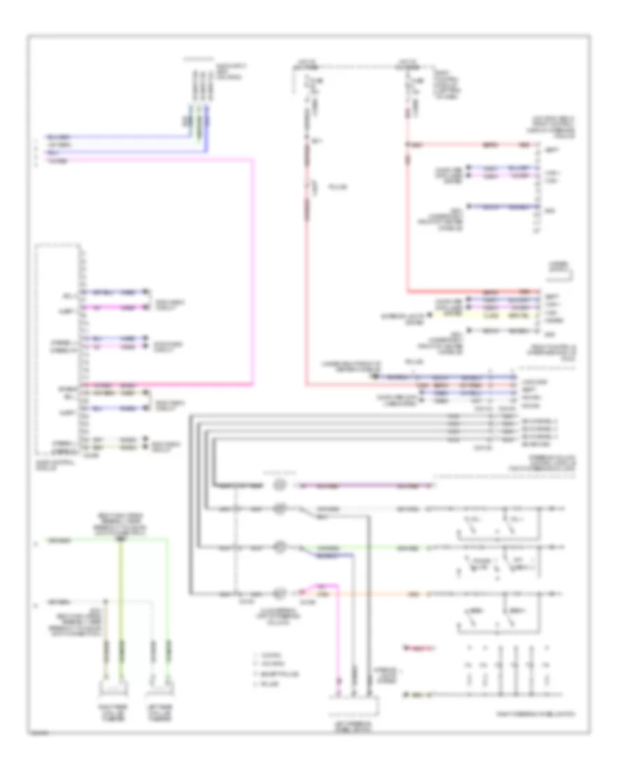
SONY Radio Wiring Diagram (2 of 2) for Ford Explorer XLT 2014
 https://portal-diagnostov.com/license.html
Automotive Electricians Portal FZCO
Automotive Electricians Portal FZCO
https://portal-diagnostov.com/license.html
https://portal-diagnostov.com/license.html
Automotive Electricians Portal FZCO
Automotive Electricians Portal FZCOList of elements for SONY Radio Wiring Diagram (2 of 2) for Ford Explorer XLT 2014:
- (body main wiring assembly, near breakout to hs-can joint connector 4) s330
- (under right front of center console) g201
- (w/o sync gen 2) front control/ display interface module
- A/d channel 2
- A/d channel 3
- A/d channel 4
- A/d return
- Alert +
- Alert -
- Audio control module
- Audio input jack (w/o sync)
- Body control module (left end of dash)
- C218b
- C218c
- C2280a
- C2280b
- C240b
- C2414a
- C2414d
- C263
- Clockspring (top of steering column)
- Cls32
- Computer data lines system
- Enable
- Except police
- Exterior lights system
- Front controls interface module (fcim)
- Fuse 10a
- Fuse 15a
- G201 (under right front of center console)
- Gd214
- Gnd
- Hazard
- Hazard switch
- Hot at all times
- Hs can+
- Hs can-
- I can +
- I can -
- Interior lights system
- Left rear d-pillar tweeter
- Left steering wheel switch
- Logic gnd
- Media
- Mute
- Nca
- Phone
- Pnk
- Police
- Ptt
- Red
- Right rear d-pillar tweeter
- Right steering wheel switch
- Rme52
- Rme53
- Rme80
- S203
- S211
- S331 (body main wiring assembly, near breakout to hs-can joint connector 4)
- Sbp09
- Sbp23
- Sdl h
- Sdl l
- Seek +
- Seek -
- Sme23
- St input 2l+
- St input 2r+
- St input 2r-
- Steering column control module (top of steering column)
- Stereo l+
- Stereo l-
- Stereo r+
- Stereo r-
- Sync radio circuit
- Vbatt
- Vdb04
- Vdb05
- Vdb13
- Vdb14
- Vme52
- Vme53
- Vme80
- Vme90
- Vme91
- Vol +
- Vol -
- W/ sync
- W/o sync
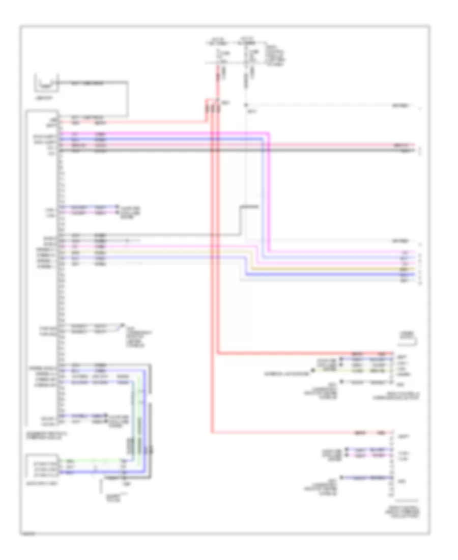
SYNC Radio Wiring Diagram, with SYNC GEN 1 (1 of 2) for Ford Explorer XLT 2014
 https://portal-diagnostov.com/license.html
Automotive Electricians Portal FZCO
Automotive Electricians Portal FZCO
https://portal-diagnostov.com/license.html
https://portal-diagnostov.com/license.html
Automotive Electricians Portal FZCO
Automotive Electricians Portal FZCOList of elements for SYNC Radio Wiring Diagram, with SYNC GEN 1 (1 of 2) for Ford Explorer XLT 2014:
- (usb cable)
- Accessory protocol interface module
- Audio input jack
- Body control module (left end of dash)
- C2280a
- C2280b
- C237
- Cls32
- Computer data lines system
- Dme45
- Dme52
- Dme80
- Dmm23
- Except police
- Exterior lights system
- Front control/ display interface module (fcdim)
- Front controls interface module (fcim)
- Fuse 10a
- Fuse 20a
- G201 (under right front of center console)
- Gd214
- Gnd
- Hazard
- Hazard switch
- Hot at all times
- Hs can +
- Hs can -
- I can +
- I can -
- Mic +
- Mic -
- Nca
- Pwr gnd
- Red
- Rme46
- Rme52
- Rme53
- Rme80
- S203
- S212
- Sbp09
- Shield
- St input 2l+
- St input 2r+
- St input 2r-
- Stereo 2l+
- Stereo 2r+
- Stereo 2r-
- Stereo l +
- Stereo l -
- Stereo r +
- Stereo r -
- Stereo shield
- Sync alert+
- Sync alert-
- Usb
- Usb port
- Vbatt
- Vdb04
- Vdb05
- Vdb13
- Vdb14
- Vme45
- Vme46
- Vme52
- Vme53
- Vme80
- Vmm23
SYNC Radio Wiring Diagram, with SYNC GEN 1 (2 of 2) for Ford Explorer XLT 2014
 https://portal-diagnostov.com/license.html
Automotive Electricians Portal FZCO
Automotive Electricians Portal FZCO
https://portal-diagnostov.com/license.html
https://portal-diagnostov.com/license.html
Automotive Electricians Portal FZCO
Automotive Electricians Portal FZCOList of elements for SYNC Radio Wiring Diagram, with SYNC GEN 1 (2 of 2) for Ford Explorer XLT 2014:
- (under right front of center console) g201
- (w/ satellite radio)
- A/d channel 2
- A/d channel 3
- A/d channel 4
- A/d return
- Am/fm
- Antenna module (center rear of roof)
- Antenna pwr
- Audio control module (acm)
- Batt
- Body control module (left end of dash)
- C210
- C211
- C218b
- C218c
- C2280a
- C240a
- C240b
- C2414a
- C2414d
- C263
- C317
- Clockspring (top of steering column)
- Coaxial cable
- Computer data lines system
- Except police
- Fuse 15a
- G201 (under right front of center console)
- Gd214
- Global positioning system module (left side of dash)
- Gnd
- Hot at all times
- Hs can+
- Hs can-
- I can +
- I can -
- Interior lights system
- Left steering wheel switch
- Logic gnd
- Mic +
- Mic -
- Microphone (in overhead console)
- Ms can +
- Ms can -
- Nca
- Phone
- Pnk
- Police
- Ptt
- Right steering wheel switch
- Rme52
- Rme53
- Rme80
- S211
- Sbp23
- Sbp29
- Sdars
- Seek +
- Seek -
- State solid
- Steering column control module (top of steering column)
- Stereo l +
- Stereo l -
- Stereo r +
- Stereo r -
- Sync alert+
- Sync alert-
- Vbatt
- Vdb04
- Vdb05
- Vdb06
- Vdb07
- Vdb13
- Vdb14
- Vme43
- Vme52
- Vme53
- Vme80
- Vol +
- Vol -
SYNC Radio Wiring Diagram, with SYNC GEN 2 (1 of 2) for Ford Explorer XLT 2014
 https://portal-diagnostov.com/license.html
Automotive Electricians Portal FZCO
Automotive Electricians Portal FZCO
https://portal-diagnostov.com/license.html
https://portal-diagnostov.com/license.html
Automotive Electricians Portal FZCO
Automotive Electricians Portal FZCOList of elements for SYNC Radio Wiring Diagram, with SYNC GEN 2 (1 of 2) for Ford Explorer XLT 2014:
- (center rear of roof) antenna module
- (in overhead console) microphone
- (left side of dash) global positioning system module
- (w/ satellite radio)
- 5v pwr
- Accessory protocol interface module
- Alert+
- Alert-
- Am/fm
- Antenna pwr
- Audio control module
- Audio digital signal processing (dsp) module (base of right "c" pillar)
- Aux audio l+
- Aux audio l-
- Aux audio r+
- Aux audio r-
- Batt
- Body control module (left end of dash)
- C210
- C211
- C2280a
- C2280b
- C237
- C240a
- C240b
- C317
- Coaxial cable
- Computer data lines system
- Dme45
- Dme52
- Dme80
- Dmm23
- Fuse 10a
- Fuse 20a
- G201 (under right front of center console)
- Gd214
- Gnd
- Hot at all times
- Hs can +
- Hs can -
- I can +
- I can -
- Lme89
- Media gnd
- Media hub
- Mic +
- Mic -
- Ms can +
- Ms can -
- Nca
- Pwr gnd
- Red
- Rme45
- Rme46
- Rme52
- Rme53
- Rme80
- Rme89
- Rmp19
- S203
- S212
- Sbp09
- Sbp29
- Sdars
- Sdl h
- Sdl l
- Shield
- State solid
- Stereo l +
- Stereo l -
- Stereo r +
- Stereo r -
- Usb
- Usb cable
- Vbatt
- Vdb04
- Vdb05
- Vdb06
- Vdb07
- Vdb13
- Vdb14
- Video +
- Video -
- Vme43
- Vme45
- Vme46
- Vme52
- Vme53
- Vme80
- Vme90
- Vme91
- Vmm23
- Vmp19
SYNC Radio Wiring Diagram, with SYNC GEN 2 (2 of 2) for Ford Explorer XLT 2014
 https://portal-diagnostov.com/license.html
Automotive Electricians Portal FZCO
Automotive Electricians Portal FZCO
https://portal-diagnostov.com/license.html
https://portal-diagnostov.com/license.html
Automotive Electricians Portal FZCO
Automotive Electricians Portal FZCOList of elements for SYNC Radio Wiring Diagram, with SYNC GEN 2 (2 of 2) for Ford Explorer XLT 2014:
- (under right front of center console) g201
- A/d channel 2
- A/d channel 3
- A/d channel 4
- A/d return
- Body control module (left end of dash)
- C211
- C218b
- C218c
- C2280a
- C2280b
- C2280c
- C2280d
- C2414a
- C2414d
- C263
- C494
- C935
- Clockspring (top of steering column)
- Cls32
- Computer data lines system
- Computer data lines system exterior lights system
- Except police
- Front controls interface module (fcim)
- Fuse 10a
- Fuse 15a
- G201 (under right front of center console)
- G301 (left rear quarter panel)
- Gd214
- Gnd
- Hazard
- Hazard switch
- Hot at all times
- Hot in run or start
- Hs can+
- Hs can-
- I can +
- I can -
- Interior lights system
- Left steering wheel switch
- Lin 03
- Logic gnd
- Micro
- Nca
- Phone
- Pnk
- Police
- Ptt
- Red
- Right steering wheel switch
- S203
- S211
- S250
- S328
- S410
- Sbp09
- Sbp23
- Seek +
- Seek -
- Shield
- Steering column control module (top of steering column)
- Vbatt
- Vdb04
- Vdb05
- Vdb13
- Vdb14
- Video camera (w/o lane departure warning) (left side of liftgate)
- Video+
- Video-
- Vol +
- Vol -
- Vpwr

 Čeština
 Dansk
Dansk Deutsch
 Ελληνικά
 English
 English
 Español
 Suomi
Suomi Français
 Français
 עברית
עברית Hrvatski
 Magyar
 Italiano
 한국어
한국어 Nederlands
 Polski
 Português
 Português
 Română
 Русский
 Slovenčina
 Slovenščina
 Svenska
 Türkçe
 中文 (中国)
