
 Čeština
 Dansk
Dansk Deutsch
 Ελληνικά
 English
 English
 Español
 Suomi
Suomi Français
 Français
 עברית
עברית Hrvatski
 Magyar
 Italiano
 한국어
한국어 Nederlands
 Polski
 Português
 Português
 Română
 Русский
 Slovenčina
 Slovenščina
 Svenska
 Türkçe
 中文 (中国)

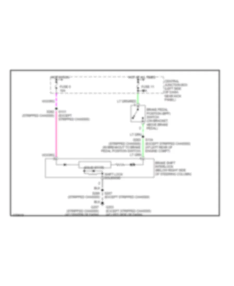
SHIFT INTERLOCK
Shift Interlock Wiring Diagram for Ford Econoline E350 Super Duty 2003
List of elements for Shift Interlock Wiring Diagram for Ford Econoline E350 Super Duty 2003:

AIR CONDITIONINGANTI-LOCK BRAKESHORNCRUISE CONTROLCOMPUTER DATA LINESEXTERIOR LIGHTSGROUND DISTRIBUTIONHEADLIGHTSINTERIOR LIGHTSPOWER DISTRIBUTIONPOWER SEATSENGINE PERFORMANCEINSTRUMENT CLUSTERRADIOPOWER MIRRORSPOWER WINDOWSSHIFT INTERLOCKPOWER DOOR LOCKSSUPPLEMENTAL RESTRAINTSSTARTING/CHARGINGTRANSMISSIONWARNING SYSTEMSWIPER/WASHER