ENGINE PERFORMANCE
5.3L VIN 0
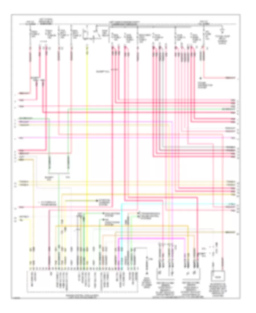
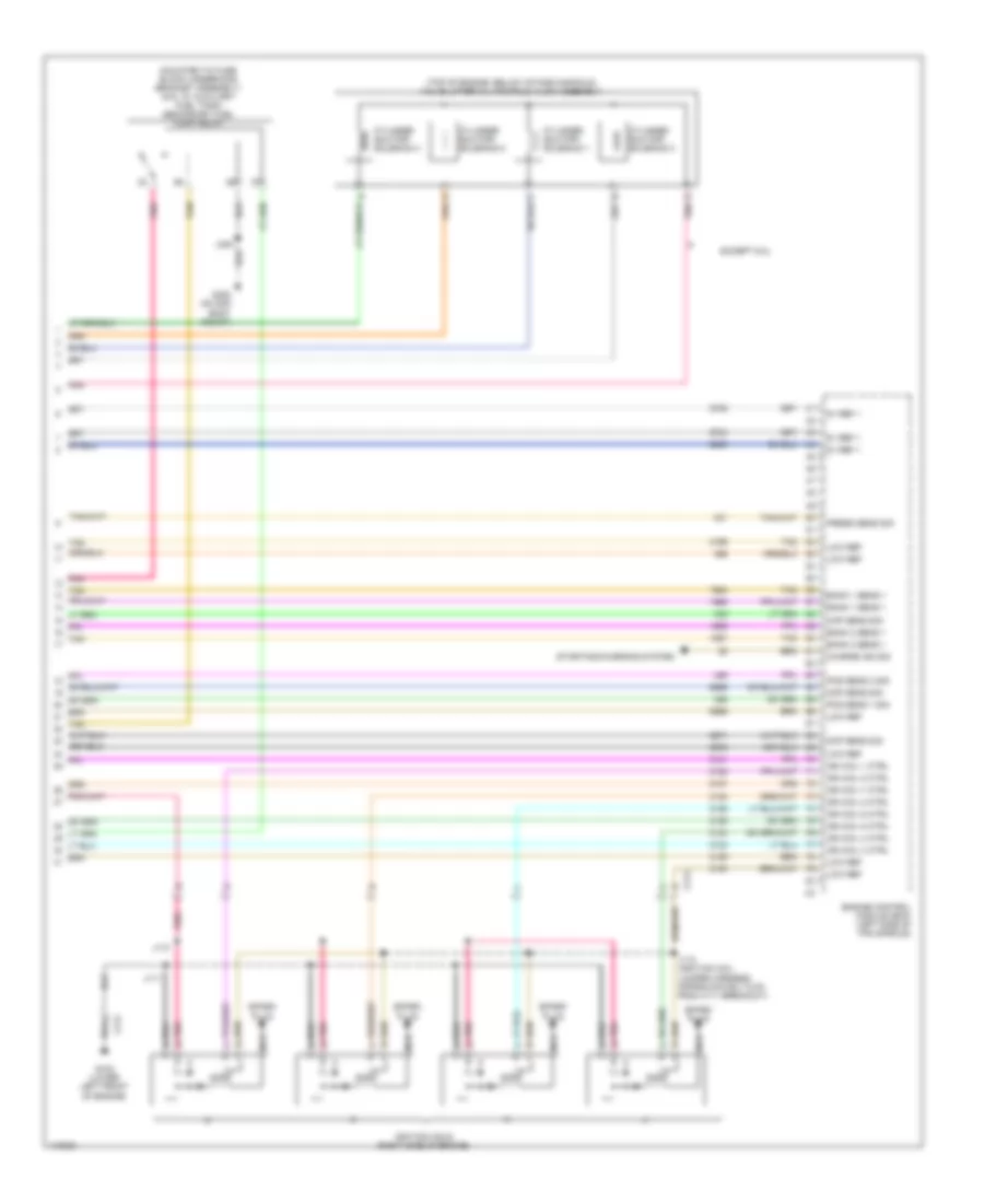
5.3L VIN 0, Engine Performance Wiring Diagram (1 of 6) for GMC Yukon Denali 2014
 https://portal-diagnostov.com/license.html
Automotive Electricians Portal FZCO
Automotive Electricians Portal FZCO
https://portal-diagnostov.com/license.html
https://portal-diagnostov.com/license.html
Automotive Electricians Portal FZCO
Automotive Electricians Portal FZCO
List of elements for 5.3L VIN 0, Engine Performance Wiring Diagram (1 of 6) for GMC Yukon Denali 2014:
- (10 series: chassis harness 5 cm from breakout to fuel tank) (20 series: chassis harness 5 cm from breakout to rear fuel pump)
- (fuel pump flow control module: on right side frame rail) (except 6.0l w/ integrated trailer brake) fuel pump/trailer brake control module (except 6.0l w/o integrated trailer brake) fuel pump flow control module
- (on 3rd body mount) (w/ 20 series) g305 g400 (w/ 10 series) (left rear body mount)
- (on fuel rail assembly) fuel pressure sensor
- (or 239)
- 5 volt ref
- 5v ref
- 5v ref 1
- 6.0l
- Accelerator pedal position (app) sensor (top of accelerator pedal assembly)
- Air conditioning system
- Bank 1 sens 2
- Body control module (bcm) (left side of dash)
- Brake pedal position (bpp) sensor (top of brake pedal assembly)
- Brake sw sig
- Brk sens sig
- Brk snse sig
- Computer data lines system
- Cooling fans system
- Data bus +
- Data bus -
- Engine control module (ecm) (left side of fan shroud)
- Except 6.0l
- Extension shld
- Exterior lights system
- Fan rly ctrl
- Front fuel pump & sender assembly (except 6.0l) (inside primary fuel tank)
- Fuel tank pressure (ftp) sensor (on fuel pump & sender assembly)
- G103 (front of right cylinder head)
- Gnd
- Iat sens sig
- Ign volt
- Ign voltage
- J106
- J331
- J364 (chassis harness, 13 cm from fuel pump flow control module breakout)
- Level sens sig
- Low ref
- Maf
- Mass air flow (maf)/intake air temperature (iat) sensor (on engine air cleaner box)
- Nca
- P/n sig
- Pnk
- Pnk d
- Pos sens 1 sig
- Pos sens 2 sig
- Press sens sig
- Pump ctrl
- Relay ctrl
- Sens sig
- Serial data
- Tan
- Tan a
- Transfer case & two speed active transfer case push button control
- Transmissions system
- W/ active 2 speed push button control transfer case
- W/ integrated trailer brake
- W/ single speed active
- W/o active 2 speed push button control transfer case
- W/o integrated trailer brake
- W/o single speed active transfer case & two speed active transfer case push button control
- X109
- X123
- X131
- X205
- X300
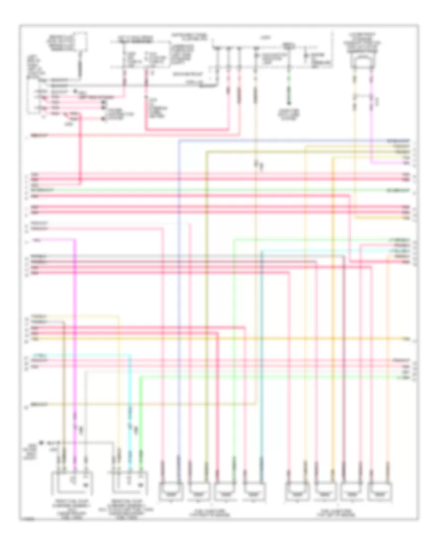
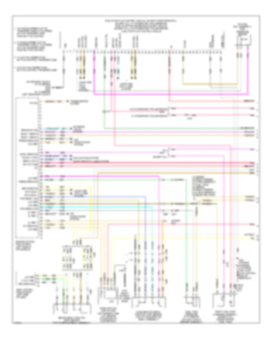
5.3L VIN 0, Engine Performance Wiring Diagram (2 of 6) for GMC Yukon Denali 2014
 https://portal-diagnostov.com/license.html
Automotive Electricians Portal FZCO
Automotive Electricians Portal FZCO
https://portal-diagnostov.com/license.html
https://portal-diagnostov.com/license.html
Automotive Electricians Portal FZCO
Automotive Electricians Portal FZCOList of elements for 5.3L VIN 0, Engine Performance Wiring Diagram (2 of 6) for GMC Yukon Denali 2014:
- (left side of engine compt) underhood fuse block
- (not used) x300
- (or 821)
- 5v ref 1
- 6.0l
- Air conditioning system
- Bank 1 sens 2
- Bank 2 sens 2
- Clutch rly ctrl
- Cooling fans system
- Ecm- batt fuse 12 10a
- Ecm- ign fuse 56 15a
- Ecm/throt cont fuse 5 15a
- Enable rly ctrl
- Eng fuse 4 15a
- Engine control module (ecm) (left side of fan shroud)
- Evaporative emission (evap) canister vent solenoid valve (near evap canister)
- Except 6.0l
- Fan rly ctrl
- Fscm fuse 21 20a
- G103 (front of right cylinder head)
- Ground
- Heated oxygen sensor (ho2s) bank 1 sensor 2 (in left exhaust, downstream of catalytic converter)
- Heated oxygen sensor (ho2s) bank 2 sensor 2 (in right exhaust, downstream of catalytic converter)
- Hot at all times
- Hot w/ run/ crank relay energized
- Ign
- Inj-a fuse 24 20a
- Inj-b fuse 13 20a
- Ipc fuse 10a
- J106
- Low ref
- Lvl sens sig
- Maf sens sig
- Mil ctrl
- Nca
- O2-a snsr fuse 18 10a
- O2-b snsr fuse 8 10a
- Pnk
- Pnk d
- Power brake
- Power distribution system
- Pump rly ctrl
- Pwr/ trn relay
- Rly coil ctrl
- Sig return
- Speed sig
- Starting/ charging system
- Tan
- Tan a
- Tcm- batt fuse 14 15a
- To fuel pump relay diagram (5 of 6)
- Tos sig
- Transmissions & cruise control systems
- Vent sol ctrl
- W/ hydraulic
- X131
- X300
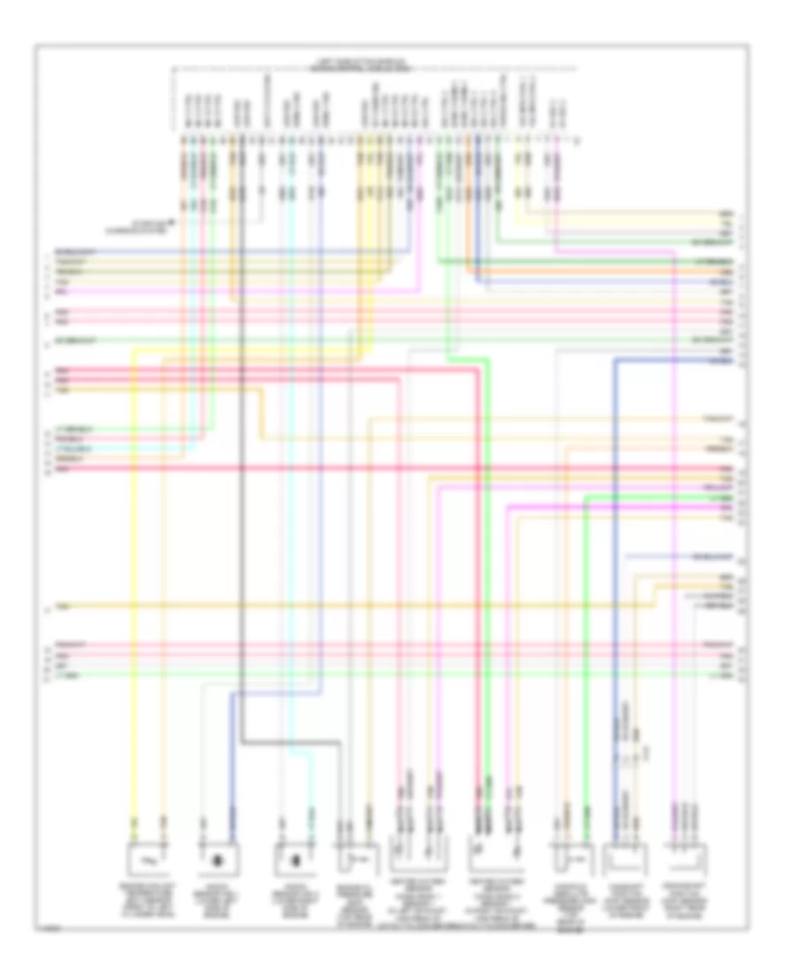
5.3L VIN 0, Engine Performance Wiring Diagram (3 of 6) for GMC Yukon Denali 2014
 https://portal-diagnostov.com/license.html
Automotive Electricians Portal FZCO
Automotive Electricians Portal FZCO
https://portal-diagnostov.com/license.html
https://portal-diagnostov.com/license.html
Automotive Electricians Portal FZCO
Automotive Electricians Portal FZCOList of elements for 5.3L VIN 0, Engine Performance Wiring Diagram (3 of 6) for GMC Yukon Denali 2014:
- (left end of dash) left i/p junction block
- (lower front of engine) camshaft position (cmp) actuator solenoid valve
- Aux hvac-ign fuse 48 10a
- Brake fluid level switch (brake fluid reservoir)
- Cadillac
- Computer data lines system
- Engine oil pressure ind
- Front fuel pump & sender assembly (6.0l) (inside primary fuel tank)
- Fuel injectors (top left of engine)
- Fuel injectors (top right of engine)
- G201 (left end of dash)
- G300 (on 2nd body mount)
- Gmc/chevrolet
- Gnd
- Hot w/ run/ crank relay energized
- Ign
- Instrument panel cluster (ipc)
- J219 (w/ steering wheel heater)
- J300
- Logic
- Malfunction indicator lamp
- Misc ign fuse 43 10a
- Pnk
- Pnk a
- Power distribution system
- Rear fuel pump & sender assembly (6.0l w/ auxiliary fuel tank) (inside secondary fuel tank)
- Serial data
- Tan
- Tan b
- Underhood fuse block (left side of engine compt)
- X109
- X112
- X205
- X300
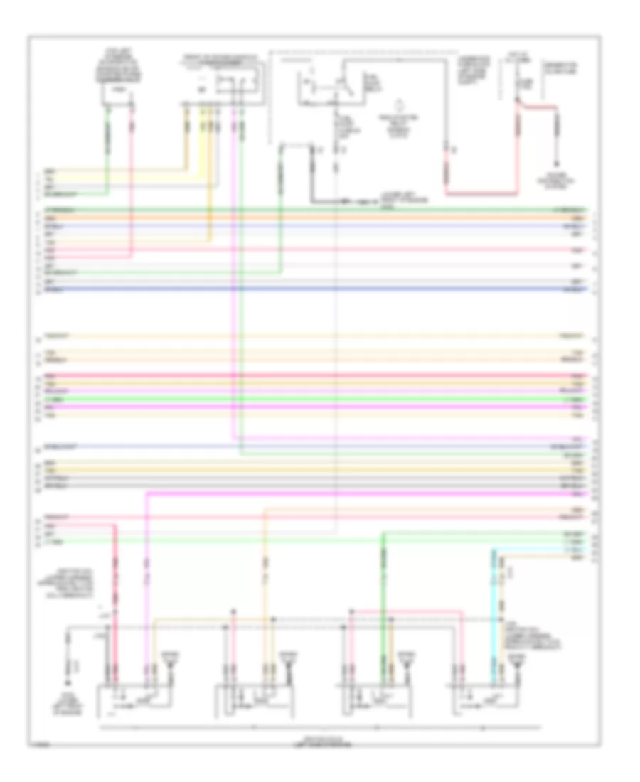
5.3L VIN 0, Engine Performance Wiring Diagram (4 of 6) for GMC Yukon Denali 2014
 https://portal-diagnostov.com/license.html
Automotive Electricians Portal FZCO
Automotive Electricians Portal FZCO
https://portal-diagnostov.com/license.html
https://portal-diagnostov.com/license.html
Automotive Electricians Portal FZCO
Automotive Electricians Portal FZCOList of elements for 5.3L VIN 0, Engine Performance Wiring Diagram (4 of 6) for GMC Yukon Denali 2014:
- (left side of fan shroud) engine control module (ecm)
- 5v ref 2
- Bank 1 sens 1
- Bank 2 sens 1
- Camshaft position (cmp) sensor (lower front of engine)
- Crankshaft position (ckp) sensor (right rear of engine)
- Duty cycle sig
- Ect sens sig
- Engine coolant temperature (ect) sensor (front of left cylinder head)
- Engine oil pressure (eop) sensor (top rear of engine)
- Heated oxygen sensor (ho2s) bank 1 sensor 1 (in left exhaust, upstream of catalytic converter)
- Heated oxygen sensor (ho2s) bank 2 sensor 1 (in right exhaust, upstream of catalytic converter)
- Inj 1 ctrl
- Inj 2 ctrl
- Inj 3 ctrl
- Inj 4 ctrl
- Inj 5 ctrl
- Inj 6 ctrl
- Inj 7 ctrl
- Inj 8 ctrl
- Knock sensor (ks) 1 (lower left side of engine)
- Knock sensor (ks) 2 (lower right side of engine)
- Low ref
- Manifold absolute pressure (map) sensor (top rear of engine)
- Nca
- Pnk
- Purge sol ctrl
- Sens 1 sig
- Sens 2 sig
- Sol ctrl
- Sol ctrl 1
- Sol ctrl 2
- Sol ctrl 3
- Sol ctrl 4
- Starting/ charging system
- Tac mtr ctrl 1
- Tac mtr ctrl 2
- Tan
- X112
5.3L VIN 0, Engine Performance Wiring Diagram (5 of 6) for GMC Yukon Denali 2014
 https://portal-diagnostov.com/license.html
Automotive Electricians Portal FZCO
Automotive Electricians Portal FZCO
https://portal-diagnostov.com/license.html
https://portal-diagnostov.com/license.html
Automotive Electricians Portal FZCO
Automotive Electricians Portal FZCOList of elements for 5.3L VIN 0, Engine Performance Wiring Diagram (5 of 6) for GMC Yukon Denali 2014:
- (front of intake manifold) throttle body
- (ignition coil jumper harness, approximately 3 cm from ignition coil 5 breakout)
- (lower left front of engine) g102
- (top left of engine) evaporative emission (evap) canister purge solenoid valve
- From pwr/trn relay diagram (2 of 6)
- Fuel pump fuse 20 20a
- Fuel pump relay
- Fuse 175a
- G102 (lower left front of engine)
- Generator inline fuse
- Hot at all times
- Ignition coils (left side of engine)
- J105
- J107
- J108
- J109 (ignition coil jumper harness, approximately 5 cm from x111 breakout)
- Nca
- Pnk
- Pnk d
- Power distribution system
- Spark plug
- Tan
- Underhood fuse block (left side of engine compt)
- X111
5.3L VIN 0, Engine Performance Wiring Diagram (6 of 6) for GMC Yukon Denali 2014
 https://portal-diagnostov.com/license.html
Automotive Electricians Portal FZCO
Automotive Electricians Portal FZCO
https://portal-diagnostov.com/license.html
https://portal-diagnostov.com/license.html
Automotive Electricians Portal FZCO
Automotive Electricians Portal FZCOList of elements for 5.3L VIN 0, Engine Performance Wiring Diagram (6 of 6) for GMC Yukon Denali 2014:
- (mounted to fuse block underhood bracket assembly) (6.0l w/ auxiliary fuel tank) secondary fuel pump relay
- (top of engine, below intake manifold) valve lifter oil manifold (vlom) assembly
- 5v ref 1
- Bank 1 sens 1
- Bank 2 sens 1
- Charge ind sig
- Ckp sens sig
- Cmp sens sig
- Cylinder shutoff solenoid 1
- Cylinder shutoff solenoid 2
- Cylinder shutoff solenoid 3
- Cylinder shutoff solenoid 4
- E pnk
- Engine control module (ecm) (left side of fan shroud)
- Except 6.0l
- G102 (lower left front of engine)
- G300 (on 2nd body mount)
- Ign coil 1 ctrl
- Ign coil 2 ctrl
- Ign coil 3 ctrl
- Ign coil 4 ctrl
- Ign coil 5 ctrl
- Ign coil 6 ctrl
- Ign coil 7 ctrl
- Ign coil 8 ctrl
- Ignition coils (right side of engine)
- J110
- J111
- J112 (ignition coil jumper harness, approximately 5 cm from x111 breakout)
- J300
- Low ref
- Map sens sig
- Nca
- Pnk
- Pnk d
- Pos sens 1 sig
- Pos sens 2 sig
- Press sens sig
- Spark plug
- Starting/charging system
- Tan
- X113
6.2L VIN F
6.2L VIN F, Engine Performance Wiring Diagram (1 of 6) for GMC Yukon Denali 2014
 https://portal-diagnostov.com/license.html
Automotive Electricians Portal FZCO
Automotive Electricians Portal FZCO
https://portal-diagnostov.com/license.html
https://portal-diagnostov.com/license.html
Automotive Electricians Portal FZCO
Automotive Electricians Portal FZCOList of elements for 6.2L VIN F, Engine Performance Wiring Diagram (1 of 6) for GMC Yukon Denali 2014:
- (10 series: chassis harness 5 cm from breakout to fuel tank) (20 series: chassis harness 5 cm from breakout to rear fuel pump)
- (fuel pump flow control module: on right side frame rail) (except 6.0l w/ integrated trailer brake) fuel pump/trailer brake control module (except 6.0l w/o integrated trailer brake) fuel pump flow control module
- (on 3rd body mount) (w/ 20 series) g305 g400 (w/ 10 series) (left rear body mount)
- (on fuel rail assembly) fuel pressure sensor
- (or 239)
- 5 volt ref
- 5v ref
- 5v ref 1
- 6.0l
- Accelerator pedal position (app) sensor (top of accelerator pedal assembly)
- Air conditioning system
- Bank 1 sens 2
- Body control module (bcm) (left side of dash)
- Brake pedal position (bpp) sensor (top of brake pedal assembly)
- Brake sw sig
- Brk sens sig
- Brk snse sig
- Computer data lines system
- Cooling fans system
- Data bus +
- Data bus -
- Engine control module (ecm) (left side of fan shroud)
- Except 6.0l
- Extension shld
- Exterior lights system
- Fan rly ctrl
- Front fuel pump & sender assembly (except 6.0l) (inside primary fuel tank)
- Fuel tank pressure (ftp) sensor (on fuel pump & sender assembly)
- G103 (front of right cylinder head)
- Gnd
- Iat sens sig
- Ign volt
- Ign voltage
- J106
- J331
- J364 (chassis harness, 13 cm from fuel pump flow control module breakout)
- Level sens sig
- Low ref
- Maf
- Mass air flow (maf)/intake air temperature (iat) sensor (on engine air cleaner box)
- Nca
- P/n sig
- Pnk
- Pnk d
- Pos sens 1 sig
- Pos sens 2 sig
- Press sens sig
- Pump ctrl
- Relay ctrl
- Sens sig
- Serial data
- Tan
- Tan a
- Transfer case & two speed active transfer case push button control
- Transmissions system
- W/ active 2 speed push button control transfer case
- W/ integrated trailer brake
- W/ single speed active
- W/o active 2 speed push button control transfer case
- W/o integrated trailer brake
- W/o single speed active transfer case & two speed active transfer case push button control
- X109
- X123
- X131
- X205
- X300
6.2L VIN F, Engine Performance Wiring Diagram (2 of 6) for GMC Yukon Denali 2014
 https://portal-diagnostov.com/license.html
Automotive Electricians Portal FZCO
Automotive Electricians Portal FZCO
https://portal-diagnostov.com/license.html
https://portal-diagnostov.com/license.html
Automotive Electricians Portal FZCO
Automotive Electricians Portal FZCOList of elements for 6.2L VIN F, Engine Performance Wiring Diagram (2 of 6) for GMC Yukon Denali 2014:
- (left side of engine compt) underhood fuse block
- (not used) x300
- (or 821)
- 5v ref 1
- 6.0l
- Air conditioning system
- Bank 1 sens 2
- Bank 2 sens 2
- Clutch rly ctrl
- Cooling fans system
- Ecm- batt fuse 12 10a
- Ecm- ign fuse 56 15a
- Ecm/throt cont fuse 5 15a
- Enable rly ctrl
- Eng fuse 4 15a
- Engine control module (ecm) (left side of fan shroud)
- Evaporative emission (evap) canister vent solenoid valve (near evap canister)
- Except 6.0l
- Fan rly ctrl
- Fscm fuse 21 20a
- G103 (front of right cylinder head)
- Ground
- Heated oxygen sensor (ho2s) bank 1 sensor 2 (in left exhaust, downstream of catalytic converter)
- Heated oxygen sensor (ho2s) bank 2 sensor 2 (in right exhaust, downstream of catalytic converter)
- Hot at all times
- Hot w/ run/ crank relay energized
- Ign
- Inj-a fuse 24 20a
- Inj-b fuse 13 20a
- Ipc fuse 10a
- J106
- Low ref
- Lvl sens sig
- Maf sens sig
- Mil ctrl
- Nca
- O2-a snsr fuse 18 10a
- O2-b snsr fuse 8 10a
- Pnk
- Pnk d
- Power brake
- Power distribution system
- Pump rly ctrl
- Pwr/ trn relay
- Rly coil ctrl
- Sig return
- Speed sig
- Starting/ charging system
- Tan
- Tan a
- Tcm- batt fuse 14 15a
- To fuel pump relay diagram (5 of 6)
- Tos sig
- Transmissions & cruise control systems
- Vent sol ctrl
- W/ hydraulic
- X131
- X300
6.2L VIN F, Engine Performance Wiring Diagram (3 of 6) for GMC Yukon Denali 2014
 https://portal-diagnostov.com/license.html
Automotive Electricians Portal FZCO
Automotive Electricians Portal FZCO
https://portal-diagnostov.com/license.html
https://portal-diagnostov.com/license.html
Automotive Electricians Portal FZCO
Automotive Electricians Portal FZCOList of elements for 6.2L VIN F, Engine Performance Wiring Diagram (3 of 6) for GMC Yukon Denali 2014:
- (left end of dash) left i/p junction block
- (lower front of engine) camshaft position (cmp) actuator solenoid valve
- Aux hvac-ign fuse 48 10a
- Brake fluid level switch (brake fluid reservoir)
- Cadillac
- Computer data lines system
- Engine oil pressure ind
- Front fuel pump & sender assembly (6.0l) (inside primary fuel tank)
- Fuel injectors (top left of engine)
- Fuel injectors (top right of engine)
- G201 (left end of dash)
- G300 (on 2nd body mount)
- Gmc/chevrolet
- Gnd
- Hot w/ run/ crank relay energized
- Ign
- Instrument panel cluster (ipc)
- J219 (w/ steering wheel heater)
- J300
- Logic
- Malfunction indicator lamp
- Misc ign fuse 43 10a
- Pnk
- Pnk a
- Power distribution system
- Rear fuel pump & sender assembly (6.0l w/ auxiliary fuel tank) (inside secondary fuel tank)
- Serial data
- Tan
- Tan b
- Underhood fuse block (left side of engine compt)
- X109
- X112
- X205
- X300
6.2L VIN F, Engine Performance Wiring Diagram (4 of 6) for GMC Yukon Denali 2014
 https://portal-diagnostov.com/license.html
Automotive Electricians Portal FZCO
Automotive Electricians Portal FZCO
https://portal-diagnostov.com/license.html
https://portal-diagnostov.com/license.html
Automotive Electricians Portal FZCO
Automotive Electricians Portal FZCOList of elements for 6.2L VIN F, Engine Performance Wiring Diagram (4 of 6) for GMC Yukon Denali 2014:
- (left side of fan shroud) engine control module (ecm)
- 5v ref 2
- Bank 1 sens 1
- Bank 2 sens 1
- Camshaft position (cmp) sensor (lower front of engine)
- Crankshaft position (ckp) sensor (right rear of engine)
- Duty cycle sig
- Ect sens sig
- Engine coolant temperature (ect) sensor (front of left cylinder head)
- Engine oil pressure (eop) sensor (top rear of engine)
- Heated oxygen sensor (ho2s) bank 1 sensor 1 (in left exhaust, upstream of catalytic converter)
- Heated oxygen sensor (ho2s) bank 2 sensor 1 (in right exhaust, upstream of catalytic converter)
- Inj 1 ctrl
- Inj 2 ctrl
- Inj 3 ctrl
- Inj 4 ctrl
- Inj 5 ctrl
- Inj 6 ctrl
- Inj 7 ctrl
- Inj 8 ctrl
- Knock sensor (ks) 1 (lower left side of engine)
- Knock sensor (ks) 2 (lower right side of engine)
- Low ref
- Manifold absolute pressure (map) sensor (top rear of engine)
- Nca
- Pnk
- Purge sol ctrl
- Sens 1 sig
- Sens 2 sig
- Sol ctrl
- Sol ctrl 1
- Sol ctrl 2
- Sol ctrl 3
- Sol ctrl 4
- Starting/ charging system
- Tac mtr ctrl 1
- Tac mtr ctrl 2
- Tan
- X112
6.2L VIN F, Engine Performance Wiring Diagram (5 of 6) for GMC Yukon Denali 2014
 https://portal-diagnostov.com/license.html
Automotive Electricians Portal FZCO
Automotive Electricians Portal FZCO
https://portal-diagnostov.com/license.html
https://portal-diagnostov.com/license.html
Automotive Electricians Portal FZCO
Automotive Electricians Portal FZCOList of elements for 6.2L VIN F, Engine Performance Wiring Diagram (5 of 6) for GMC Yukon Denali 2014:
- (front of intake manifold) throttle body
- (ignition coil jumper harness, approximately 3 cm from ignition coil 5 breakout)
- (lower left front of engine) g102
- (top left of engine) evaporative emission (evap) canister purge solenoid valve
- From pwr/trn relay diagram (2 of 6)
- Fuel pump fuse 20 20a
- Fuel pump relay
- Fuse 175a
- G102 (lower left front of engine)
- Generator inline fuse
- Hot at all times
- Ignition coils (left side of engine)
- J105
- J107
- J108
- J109 (ignition coil jumper harness, approximately 5 cm from x111 breakout)
- Nca
- Pnk
- Pnk d
- Power distribution system
- Spark plug
- Tan
- Underhood fuse block (left side of engine compt)
- X111
6.2L VIN F, Engine Performance Wiring Diagram (6 of 6) for GMC Yukon Denali 2014
 https://portal-diagnostov.com/license.html
Automotive Electricians Portal FZCO
Automotive Electricians Portal FZCO
https://portal-diagnostov.com/license.html
https://portal-diagnostov.com/license.html
Automotive Electricians Portal FZCO
Automotive Electricians Portal FZCOList of elements for 6.2L VIN F, Engine Performance Wiring Diagram (6 of 6) for GMC Yukon Denali 2014:
- (mounted to fuse block underhood bracket assembly) (6.0l w/ auxiliary fuel tank) secondary fuel pump relay
- (top of engine, below intake manifold) valve lifter oil manifold (vlom) assembly
- 5v ref 1
- Bank 1 sens 1
- Bank 2 sens 1
- Charge ind sig
- Ckp sens sig
- Cmp sens sig
- Cylinder shutoff solenoid 1
- Cylinder shutoff solenoid 2
- Cylinder shutoff solenoid 3
- Cylinder shutoff solenoid 4
- E pnk
- Engine control module (ecm) (left side of fan shroud)
- Except 6.0l
- G102 (lower left front of engine)
- G300 (on 2nd body mount)
- Ign coil 1 ctrl
- Ign coil 2 ctrl
- Ign coil 3 ctrl
- Ign coil 4 ctrl
- Ign coil 5 ctrl
- Ign coil 6 ctrl
- Ign coil 7 ctrl
- Ign coil 8 ctrl
- Ignition coils (right side of engine)
- J110
- J111
- J112 (ignition coil jumper harness, approximately 5 cm from x111 breakout)
- J300
- Low ref
- Map sens sig
- Nca
- Pnk
- Pnk d
- Pos sens 1 sig
- Pos sens 2 sig
- Press sens sig
- Spark plug
- Starting/charging system
- Tan
- X113

 Čeština
 Dansk
Dansk Deutsch
 Ελληνικά
 English
 English
 Español
 Suomi
Suomi Français
 Français
 עברית
עברית Hrvatski
 Magyar
 Italiano
 한국어
한국어 Nederlands
 Polski
 Português
 Português
 Română
 Русский
 Slovenčina
 Slovenščina
 Svenska
 Türkçe
 中文 (中国)
