POWER DISTRIBUTION
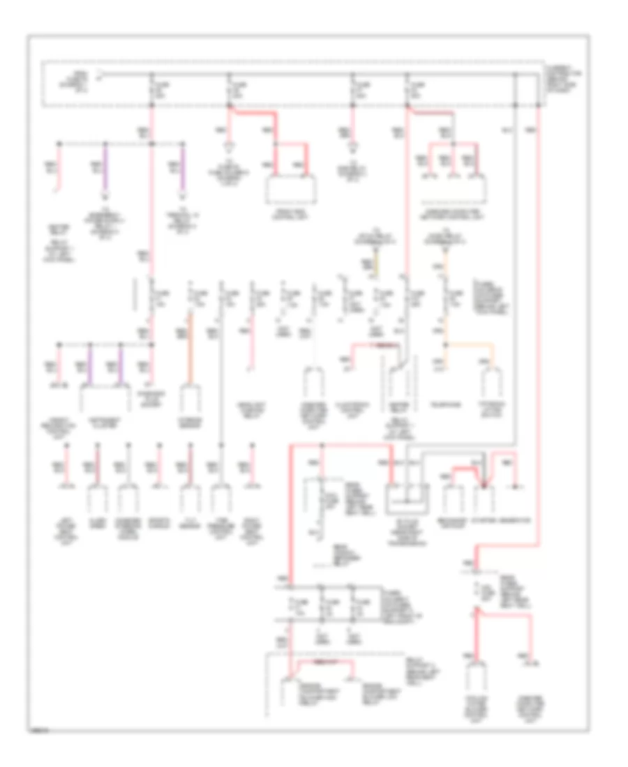
Power Distribution Wiring Diagram (1 of 4) for Porsche 911 GT3 RS 2008
 https://portal-diagnostov.com/license.html
Automotive Electricians Portal FZCO
Automotive Electricians Portal FZCO
https://portal-diagnostov.com/license.html
https://portal-diagnostov.com/license.html
Automotive Electricians Portal FZCO
Automotive Electricians Portal FZCO
List of elements for Power Distribution Wiring Diagram (1 of 4) for Porsche 911 GT3 RS 2008:
- (not used)
- Battery
- Cigar lighter
- Convertible control unit
- Current distributor (behind right side of dash)
- Driver door control unit
- Front end control unit
- Fuse e1 30a
- Fuse e2 30a
- Fuse e3 30a
- Fuse e4 (not used)
- Fuse f1 30a
- Fuse f1 80a
- Fuse f10 15a
- Fuse f2 15a
- Fuse f3 15a
- Fuse f3 70a
- Fuse f4 150a
- Fuse f4 30a
- Fuse f5 15a
- Fuse f5 50a
- Fuse f6 15a
- Fuse f7 15a
- Fuse f8 7.5a
- Fuse f8 70a
- Fuse f9 (not used)
- Fuses holder a (on fuses support, behind left kick panel)
- Fuses holder e (on fuses support, behind left kick panel)
- Gp3 (left side of support frame)
- Gp4 (center of support frame)
- Interior lights system
- Left power seat control unit
- Left power seat switch
- Left rear power window
- Left seat width adjustment switch
- Onboard computer network control unit
- Package tray plug socket
- Passenger door control unit
- Plug socket 2
- Psm control unit
- Rear control unit
- Red
- Red c
- Right power seat control unit
- Right power seat switch
- Right rear power window
- Right seat width adjustment switch
- Sun roof drive
- To fuse f1 fuse holder d (diagram 4 of 4)
- To fuse f6 (diagram 2 of 4)
- W/ memory
- W/o memory
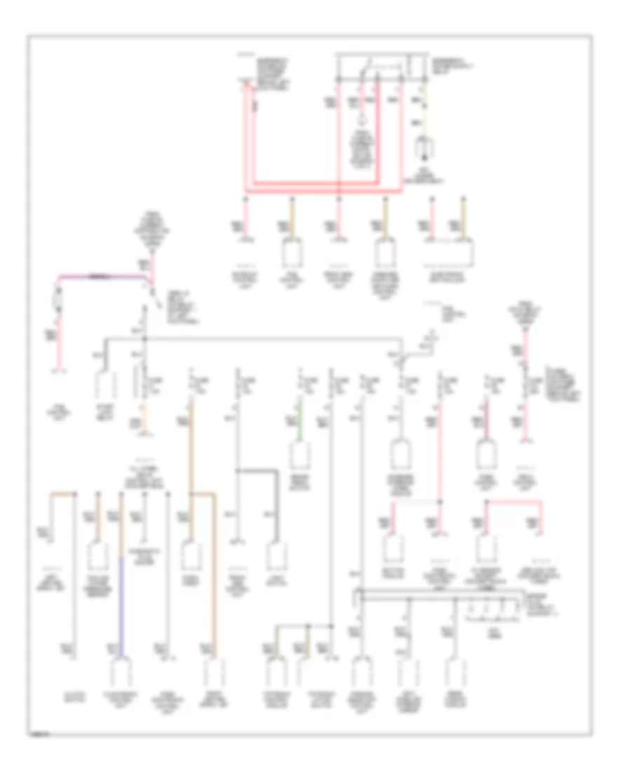
Power Distribution Wiring Diagram (2 of 4) for Porsche 911 GT3 RS 2008
 https://portal-diagnostov.com/license.html
Automotive Electricians Portal FZCO
Automotive Electricians Portal FZCO
https://portal-diagnostov.com/license.html
https://portal-diagnostov.com/license.html
Automotive Electricians Portal FZCO
Automotive Electricians Portal FZCOList of elements for Power Distribution Wiring Diagram (2 of 4) for Porsche 911 GT3 RS 2008:
- (not used)
- A14
- Alarm siren
- B+ plug socket (near right side of transmission)
- Climatronic control unit
- Combined steering wheel module
- Cooling water blower control unit
- Current distributor (behind right side of dash)
- Diagnosis plug socket
- Engine compartment blower high relay
- Engine compartment blower low relay
- From fuse f5 (diagram 1 of 4)
- Front end control unit
- Fuse f1 10a
- Fuse f1 15a
- Fuse f10 25a
- Fuse f2 3a
- Fuse f2 7.5a
- Fuse f2 80a
- Fuse f3 15a
- Fuse f3 3a
- Fuse f4 25a
- Fuse f5 7.5a
- Fuse f6 7.5a
- Fuse f6 80a
- Fuse f7 (not used)
- Fuse f7 80a
- Fuse f8 7.5a
- Fuse f9 7.5a
- Fuse f9 80a
- Fuses holder b (on fuses support, behind left kick panel)
- Fuses holder f (on fuses support f, left front of eng compt)
- Generator
- Headlight washing relay
- Heater relay
- Instrument cluster
- Interior sensor
- Left power seat control unit
- Maxi fuse 40a
- Midi fuse 80a
- Onboard computer network control unit
- Rear fuses support (behind left rear seat well)
- Rear window defogger relay
- Red
- Relay support 1 (at left kick panel)
- Relay support 2 (behind left rear seat well)
- Right power seat control unit
- Secondary air pump
- Sports chrono
- Starter
- Telephone
- Tilt sensor
- Tiptronic lifting switch
- Tire pressure control unit
- To dme relay (diagram 4 of 4)
- To fuse f9 fuse holder d (diagram 4 of 4)
- To mfi+di relay (diagram 4 of 4)
- To micro relay (diagram 4 of 4)
- To terminal 15 relay (diagram 3 of 4)
- Weight recognition control unit
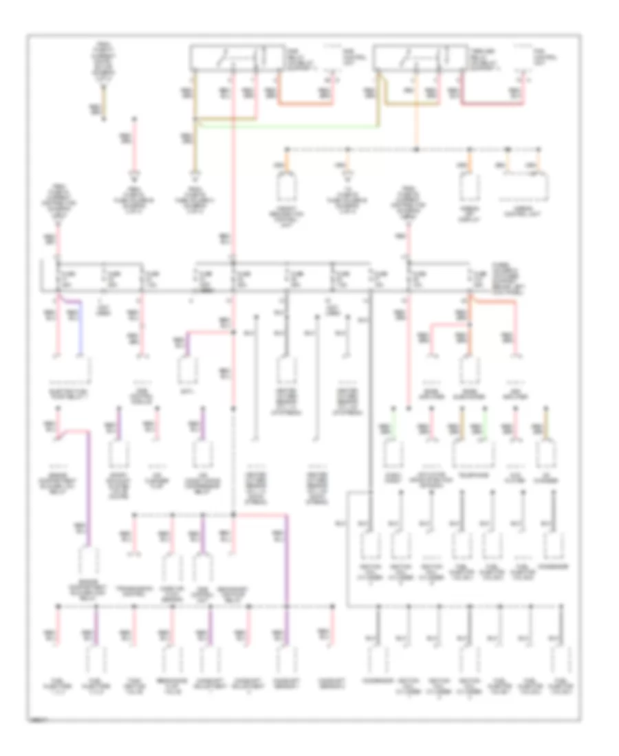
Power Distribution Wiring Diagram (3 of 4) for Porsche 911 GT3 RS 2008
 https://portal-diagnostov.com/license.html
Automotive Electricians Portal FZCO
Automotive Electricians Portal FZCO
https://portal-diagnostov.com/license.html
https://portal-diagnostov.com/license.html
Automotive Electricians Portal FZCO
Automotive Electricians Portal FZCOList of elements for Power Distribution Wiring Diagram (3 of 4) for Porsche 911 GT3 RS 2008:
- All wheel drive control unit (convertible)
- Anti- dazzling interior mirror
- Ay sensor (except convertible & turbo)
- Brake pedal switch
- Bridge plug (on relay support 1)
- Button module
- Climatronic control unit
- Clutch switch
- Combined steering wheel module
- Cooling water pressure sensor
- Diagnostic plug socket
- Drs can top (convertible & turbo)
- E box handy
- Electronic ignition lock
- Emergency power pin (on fuses support, behind left kick panel) a
- From fuse f6 current distri- butor (diagram 2 of 4)
- From fuse f6 current distributor (diagram 2 of 4)
- From mfi-di relay (diagram 4 of 4)
- Front end control unit
- Fuse f1 7.5a
- Fuse f10 25a
- Fuse f2 7.5a
- Fuse f3 10a
- Fuse f4 10a
- Fuse f5 15a
- Fuse f6 15a
- Fuse f7 7.5a
- Fuse f8 10a
- Fuse f9 15a
- Fuses holder c (on fuses support, behind left kick panel)
- Gateway control unit
- Gp7 (under driver's seat)
- Left heated spray jet
- Light switch
- Nca
- Not used
- Onboard computer network control unit
- Parking assistant control unit
- Pas control unit
- Pasm (damtronic) control unit
- Pasm control unit
- Psm 8 control unit
- Rear window module
- Red
- Right heated spray jet
- Start lock relay
- Term 15 relay (on relay support 1 at left kick panel)
- Tiptronic control module
- Tiptronic lifting switch
Power Distribution Wiring Diagram (4 of 4) for Porsche 911 GT3 RS 2008
 https://portal-diagnostov.com/license.html
Automotive Electricians Portal FZCO
Automotive Electricians Portal FZCO
https://portal-diagnostov.com/license.html
https://portal-diagnostov.com/license.html
Automotive Electricians Portal FZCO
Automotive Electricians Portal FZCOList of elements for Power Distribution Wiring Diagram (4 of 4) for Porsche 911 GT3 RS 2008:
- (not used)
- Actuator infosystem pcm or radio
- Air cleaner flap
- Air conditioning compressor relay
- Airbag control unit
- Airbag off display
- Ask amplifier
- Bose amplifier
- Bose subwoofer
- Camshaft adjustment
- Camshaft sensor 1
- Camshaft sensor 2
- Cd changer
- Condensor
- Dme control module
- Dme control unit
- Dme relay (on relay support 1)
- Dmtl
- Dvd player
- E box handy
- Electric fuel pump relay 1
- Engine compartment blower high relay
- Engine compartment blower low relay
- From fuse f4 current distributor (diagram 1 of 4)
- From fuse f7 current distri- butor (diagram 2 of 4)
- From fuse f8 fuse holder b (diagram 2 of 4)
- From fuse f9 current distributor (diagram 2 of 4)
- From fuse f9 fuse holder c (diagram 3 of 4)
- Fuel injector valve 1
- Fuel injector valve 2
- Fuel injector valve 3
- Fuel injector valve 4
- Fuel injector valve 5
- Fuel injector valve 6
- Fuel injectors 1, 2, 3
- Fuel injectors 4, 5, 6
- Fuse f1 25a
- Fuse f10 25a
- Fuse f2 25a
- Fuse f3 7.5a
- Fuse f4 (not used)
- Fuse f5 25a
- Fuse f6 25a
- Fuse f7 15a
- Fuse f8 7.5a
- Fuse f9 10a
- Fuses holder d (on fuses support, behind left kick panel)
- Heated oxygen sensor (cyl 1-3 down stream)
- Heated oxygen sensor (cyl 1-3 up stream)
- Heated oxygen sensor (cyl 4-6 down stream)
- Heated oxygen sensor (cyl 4-6 up stream)
- Ignition coil cylinder
- Mass air flow sensor
- Pas control unit
- Red
- Resonance flap valve
- Secondary air pump relay
- Sport exhaust system valve (coupe)
- Tank venting valve
- Telephone
- Term 86s relay (on relay support 1)
- To fuse f9 fuse holder b (diagram 2 of 4)
- Transmission control
- Weight recognition control unit

 Čeština
 Dansk
Dansk Deutsch
 Ελληνικά
 English
 English
 Español
 Suomi
Suomi Français
 Français
 עברית
עברית Hrvatski
 Magyar
 Italiano
 한국어
한국어 Nederlands
 Polski
 Português
 Português
 Română
 Русский
 Slovenčina
 Slovenščina
 Svenska
 Türkçe
 中文 (中国)
