STARTING/CHARGING
Charging Wiring Diagram for Pontiac G6 GXP 2008
 https://portal-diagnostov.com/license.html
Automotive Electricians Portal FZCO
Automotive Electricians Portal FZCO
https://portal-diagnostov.com/license.html
https://portal-diagnostov.com/license.html
Automotive Electricians Portal FZCO
Automotive Electricians Portal FZCO
List of elements for Charging Wiring Diagram for Pontiac G6 GXP 2008:
- (not used)
- (on left rear side of engine compt, on engine transmission stud, below upper coolant hose)
- 2.4l
- 3.5l & 3.9l
- 3.6l
- 5-volt ref
- 5-volt reference
- Battery
- Battery current sensor (3.6l)
- Battery current sensor signal
- Body control module (bcm) (under right side of center console, near dash)
- Charge ind
- Computer data lines system
- Ecm/pcm serial data
- Engine control module (ecm) (left side of engine compt)
- Except 2.4l
- G104 (on left side of engine compt, on core support, between left inflatable restraint front end sensor & g109)
- G105
- Generator
- Generator field duty cycle signal
- Generator turn on signal
- High speed gmlan serial data bus +
- High speed gmlan serial data bus -
- Ign
- Instrument panel cluster (ipc)
- Logic
- Low ref
- Low reference
- Low speed gmlan serial data
- Pnk
- Power distribution system
- Red
- Starter
- Tan
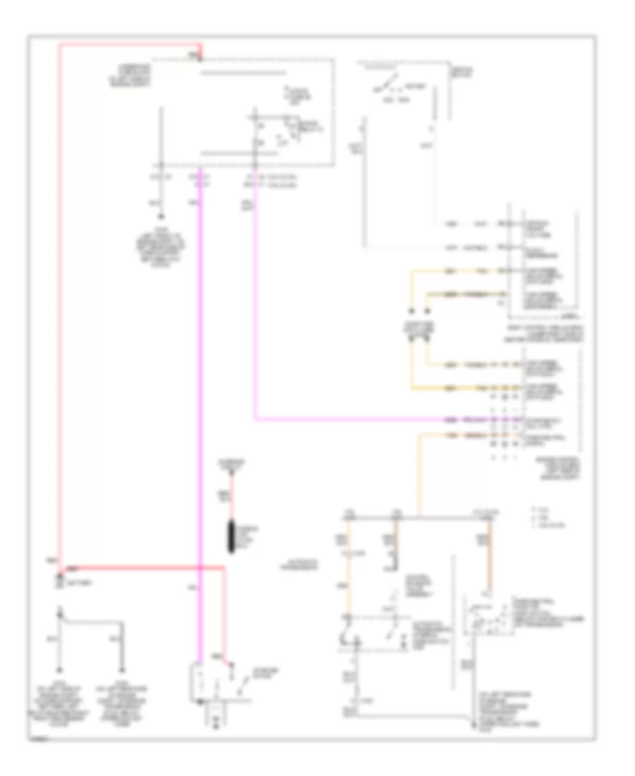
Starting Wiring Diagram for Pontiac G6 GXP 2008
 https://portal-diagnostov.com/license.html
Automotive Electricians Portal FZCO
Automotive Electricians Portal FZCO
https://portal-diagnostov.com/license.html
https://portal-diagnostov.com/license.html
Automotive Electricians Portal FZCO
Automotive Electricians Portal FZCOList of elements for Starting Wiring Diagram for Pontiac G6 GXP 2008:
- (2.4l & 3.6l)
- (3.5l & 3.9l)
- (on left rear side of engine compt, on engine transmission stud, below upper coolant hose) g105
- 2.4l
- 2.4l & 3.5l (a/t)
- 3.5l & 3.9l
- 3.6l
- 3.6l (a/t)
- 3.9l (a/t)
- 5-volt reference
- A x1
- Automatic transmission
- Automatic transmission internal mode switch (ims)
- Battery
- Body control module (bcm) (under right side of center console, near dash)
- C1 x2
- C10 x2
- Charging circuit
- Computer data lines system
- Control solenoid valve assembly
- D12 x1
- Engine control module (ecm) (left side of engine compt)
- G104 (on left side of engine compt, on core support, between left inflatable restraint front end sensor & g109)
- G105 (on left rear side of engine compt, on engine transmission stud, below upper coolant hose)
- G109 (left front of engine compt, on left rear side of core support, between g101 & g104)
- High speed gmlan serial data bus +
- High speed gmlan serial data bus -
- Ignition switch
- K x100
- Logic
- Nca
- Off
- Off/run/ crank voltage
- Park/neutral position (pnp) switch (below master cylinder, on transmission)
- Park/neutral signal
- Red
- Run acc
- Start
- Starter motor
- Starter rly coil ctrl
- Strtr fuse 26 30a
- Strtr relay 31
- Tan
- Underhood fuse block (in left side of engine compt)
- W x100
- X1 e12

 Čeština
 Dansk
Dansk Deutsch
 Ελληνικά
 English
 English
 Español
 Suomi
Suomi Français
 Français
 עברית
עברית Hrvatski
 Magyar
 Italiano
 한국어
한국어 Nederlands
 Polski
 Português
 Português
 Română
 Русский
 Slovenčina
 Slovenščina
 Svenska
 Türkçe
 中文 (中国)
