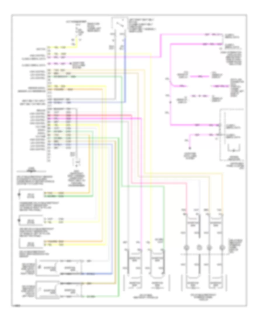
SUPPLEMENTAL RESTRAINTS
Supplemental Restraint Wiring Diagram for Pontiac Bonneville SE 2002
 https://portal-diagnostov.com/license.html
Automotive Electricians Portal FZCO
Automotive Electricians Portal FZCO
https://portal-diagnostov.com/license.html
https://portal-diagnostov.com/license.html
Automotive Electricians Portal FZCO
Automotive Electricians Portal FZCO
List of elements for Supplemental Restraint Wiring Diagram for Pontiac Bonneville SE 2002:
- A10
- A11
- A12
- A13
- A14
- A15
- A16
- A17
- A18
- Air bag indicator
- Case ground
- Class 2 serial data
- Computer data lines system
- Dash integration module (dim) (behind right side of dash, under sound insulator)
- Data link connector (dlc) (partial) (under lower left side of dash)
- Driver inflatable restraint side impact sensor (sis) (at base of left "b" pillar, behind trim panel)
- G303 (near right body harness, under right front seat on forward crossmember)
- Ground
- High control
- Hot in on & start
- Ignition
- Inflatable restraint front end discriminating sensor
- Inflatable restraint i/p module
- Inflatable restraint sensing & diagnostic module (sdm) (under rear of center console, mounted to floor pan)
- Inflatable restraint side impact module- left front
- Inflatable restraint side impact module- right front
- Inflatable restraint steering wheel module
- Inflatable restraint steering wheel module coil
- Instrument panel cluster (ipc)
- Left front seat belt switch (closed w/seat belt unbuckled) (in seat belt assembly, near floor)
- Low control
- Nca
- Passenger inflatable restraint side impact sensor (sis) (at base of right "b" pillar, behind trim panel)
- Pnk
- Rear fuse block (under left rear seat)
- Seat belt sw input
- Seat belt sw return
- Sensor low reference
- Sensor signal
- Shorting bar
- Signal
- Sir fuse 15a
- Solid state
- Tan
- Voltage
- W/ heads-up display
- W/o heads-up display
 Čeština
 Dansk
Dansk Deutsch
 Ελληνικά
 English
 English
 Español
 Suomi
Suomi Français
 Français
 עברית
עברית Hrvatski
 Magyar
 Italiano
 한국어
한국어 Nederlands
 Polski
 Português
 Português
 Română
 Русский
 Slovenčina
 Slovenščina
 Svenska
 Türkçe
 中文 (中国)
 日本語
日本語
