AIR CONDITIONING
2.2L VIN D
2.2L VIN D, Compressor Wiring Diagram for Saturn Vue Red Line 2004
 https://portal-diagnostov.com/license.html
Automotive Electricians Portal FZCO
Automotive Electricians Portal FZCO
https://portal-diagnostov.com/license.html
https://portal-diagnostov.com/license.html
Automotive Electricians Portal FZCO
Automotive Electricians Portal FZCO
List of elements for 2.2L VIN D, Compressor Wiring Diagram for Saturn Vue Red Line 2004:
- (on intake manifold, under ignition coil housing) engine control module (ecm)
- A/c clutch fuse 10a
- A/c clutch relay
- A/c compressor clutch (at lower left front of engine)
- A/c diode
- A/c press sens
- A/c refrigerant pressure sensor (in a/c high side pressure line)
- A/c req sig
- A/c request
- A12
- A6 c1
- A6 c2
- B12
- Body control module (bcm) (below front of center floor console)
- Can high
- Can low
- Clu rly ctrl
- Computer data lines system
- E10
- E11
- Evap temp sens
- Evaporator temperature sensor (in engine compartment, on expansion valve block)
- G101 (at left front of engine compt)
- Hot at all times
- Hot in run or start
- Hvac control module (at center of dash)
- Logic
- Splice pack sp101 (behind left front headlight)
- Tan
- Underhood fuse block (left side of engine compt)
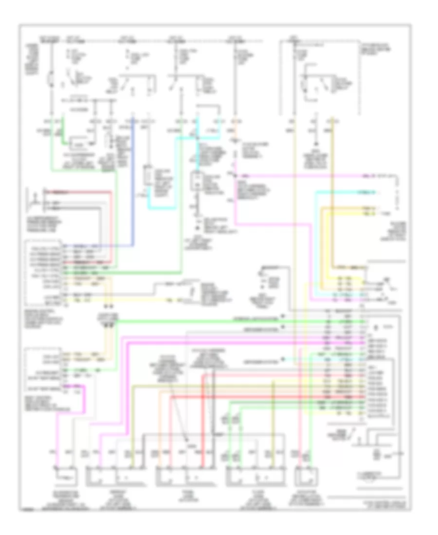
2.2L VIN D, Manual A/C Wiring Diagram for Saturn Vue Red Line 2004
 https://portal-diagnostov.com/license.html
Automotive Electricians Portal FZCO
Automotive Electricians Portal FZCO
https://portal-diagnostov.com/license.html
https://portal-diagnostov.com/license.html
Automotive Electricians Portal FZCO
Automotive Electricians Portal FZCOList of elements for 2.2L VIN D, Manual A/C Wiring Diagram for Saturn Vue Red Line 2004:
- (in hvac harness, between c202 & panel mode actuator harness breakout)
- (in hvac harness, between defrost mode & panel mode actuator harness breakout)
- A/c clutch fuse 10a
- A/c clutch relay
- A/c compressor clutch (at lower left front of engine)
- A/c diode
- A/c press sens
- A/c refrigerant pressure sensor (in a/c high side pressure line)
- A/c req sig
- A/c request
- A10 c1
- A12
- A6 c1
- A6 c2
- A7 c3
- Actuator recirculation (on lower front of hvac assembly)
- B c5
- B12
- Blower motor resistor (at right side of hvac)
- Blw mtr lo
- Body control module (bcm) (below front of center floor console)
- C2 c1
- Can high
- Can low
- Clu rly ctrl
- Computer data lines system
- Cool fan high fuse 40a
- Cool fan high relay
- Cool fan low relay
- Cool low fuse 20a
- Cooling fan motor (behind radiator)
- Cooling fan resistor (at left front of engine compt)
- D2 c2
- Def mod a
- Def mod b
- Defogger system
- Defrost mode actuator (on left side of hvac assembly)
- E10
- E11
- Ect sig
- Engine control module (ecm) (on intake manifold, under ignition coil housing)
- Engine coolant temperature (ect) sensor (on thermostat housing)
- Evap temp sens
- Evaporator temperature sensor (in engine compt, on expansion valve block)
- F12 c2
- Fan 1 rly ctrl
- Fan 2 rly ctrl
- Floor mode actuator (on left side of hvac assembly)
- Flr mod a
- Flr mod b
- G101 (at left front of engine compartment)
- G201 (behind right front kick panel)
- G203 (near lower center of dash, on i/p fuse block)
- Gnd
- High
- Hood fuse block)
- Hot at all times
- Hot in run
- Hot in run or start
- Hvac blower fuse 40a
- Hvac blower motor (on hvac assembly)
- Hvac blower relay
- Hvac control module (at center of dash)
- Hvac fuse 10a
- I/p fuse block (behind center of dash)
- Ign 1
- Illumination
- Interior lights system
- Low ref
- Off
- Pan mod a
- Pan mod b
- Panel mode actuator
- Pos sens
- Pos sig
- Rear defogger switch
- Rec dr a
- Rec dr b
- Red
- S206
- S207
- Spice pack sp201
- Splice pack sp101 (behind left front headlight)
- Splice pack sp101 (behind left g101 front (at left head- front of light) engine compt)
- Tan
- Under- hood fuse block (left side of engine compt)
3.5L VIN 4
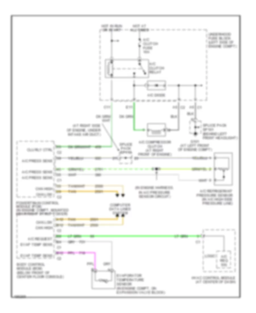
3.5L VIN 4, Compressor Wiring Diagram for Saturn Vue Red Line 2004
 https://portal-diagnostov.com/license.html
Automotive Electricians Portal FZCO
Automotive Electricians Portal FZCO
https://portal-diagnostov.com/license.html
https://portal-diagnostov.com/license.html
Automotive Electricians Portal FZCO
Automotive Electricians Portal FZCOList of elements for 3.5L VIN 4, Compressor Wiring Diagram for Saturn Vue Red Line 2004:
- (at right side
- (in engine harness,
- A/c clutch fuse 10a
- A/c clutch relay
- A/c compressor clutch (at right front of engine)
- A/c diode
- A/c press sens
- A/c refrigerant pressure sensor (in a/c high side pressure line)
- A/c req sig
- A/c request
- A12
- A6 c1
- A6 c2
- B12
- Body control module (bcm) (below front of center floor console)
- C11
- Can high
- Can low
- Clu rly ctrl
- Computer data lines system
- E11
- Evap temp sens
- Evaporator temperature sensor (in engine compt, on expansion valve block)
- G101 (at left front of engine compt)
- Hot at all times
- Hot in run or start
- Hvac control module (at center of dash)
- In a/c pressure sensor circuit)
- Logic
- Of engine, under intake air duct)
- Powertrain control module (pcm) (in engine compt, mounted near right strut tower)
- S120
- Splice pack sp101 (behind left front headlight)
- Splice pack sp113
- Tan
- Underhood fuse block (left side of engine compt)
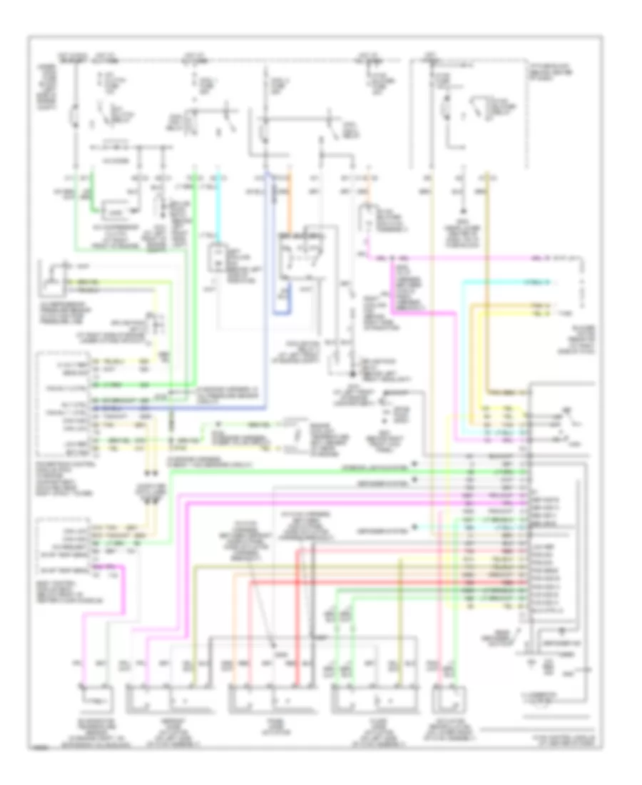
3.5L VIN 4, Manual A/C Wiring Diagram for Saturn Vue Red Line 2004
 https://portal-diagnostov.com/license.html
Automotive Electricians Portal FZCO
Automotive Electricians Portal FZCO
https://portal-diagnostov.com/license.html
https://portal-diagnostov.com/license.html
Automotive Electricians Portal FZCO
Automotive Electricians Portal FZCOList of elements for 3.5L VIN 4, Manual A/C Wiring Diagram for Saturn Vue Red Line 2004:
- (in engine harness, in
- (in engine harness, in bank 1 ho2 sensors circuit)
- (in hvac harness, between c202 & panel mode actuator harness breakout)
- (in hvac harness, between defrost mode & panel mode actuator harness breakout)
- 5 volt ref
- 87a
- A/c clutch fuse 10a
- A/c clutch relay
- A/c compressor clutch (at right front of engine)
- A/c diode
- A/c pressure sensor circuit)
- A/c refrigerant pressure sensor (in a/c high side pressure line)
- A/c req sig
- A/c request
- A11
- A12
- A2 c1
- A6 c1
- A6 c2
- A7 c3
- Actuator recirculation (on lower front of hvac assembly)
- B c5
- B11 c1
- B12
- Blower motor resistor (at right side of hvac)
- Blw mtr lo
- Body control module (bcm) (below front of center floor console)
- C10
- C11
- Can high
- Can low
- Computer data lines system
- Cool 1 fuse 25a
- Cool 2 fuse 25a
- Cool fan 1 relay
- Cool fan 2 relay
- Cooling fan relay 3 (at left front of engine compt)
- Def mod a
- Def mod b
- Defogger ind
- Defogger system
- Defrost mode actuator (on left side of hvac assembly)
- E11
- Ect sig
- Engine coolant temperature (ect) sensor (at rear of engine)
- Evap temp sens
- Evaporator temperature sensor (in engine compt, on expansion valve block)
- F2 c3
- Fan rly 1 ctrl
- Fan rly 2 ctrl
- Floor mode actuator (on left side of hvac assembly)
- Flr mod a
- Flr mod b
- Front of engine compt)
- G101 (at left front of engine compartment)
- G201 (behind right front kick panel)
- G203 (near lower center of dash, on i/p fuse block)
- Gnd
- High
- Hot at all times
- Hot in run
- Hot in run or start
- Hvac blower (on hvac assembly)
- Hvac blower fuse 40a
- Hvac blower relay
- Hvac control module (at center of dash)
- Hvac fuse 10a
- I/p fuse block (behind center of dash)
- Ign
- Illumination
- Interior lights system
- Left cooling fan (behind left side of radiator)
- Logic
- Low ref
- Off
- Pan mod a
- Pan mod b
- Panel mode actuator
- Pos sens
- Pos sig
- Powertrain control module (pcm) (in engine compartment, mounted near right strut tower)
- Rear defogger switch
- Rec dr a
- Rec dr b
- Red
- Right cooling fan (behind right side of radiator)
- Rly ctrl
- S120
- S122
- S124 (in engine harness, in egr valve circuit)
- S206
- S207
- Sens sig
- Spice pack sp201
- Splice pack sp101 (behind left front headlight)
- Splice pack sp101 (behind left g101 (at left front head- light)
- Splice pack sp113 (at right side of engine, under intake air duct)
- Tan
- Under- hood fuse block (left side of engine compt)

 Čeština
 Dansk
Dansk Deutsch
 Ελληνικά
 English
 English
 Español
 Suomi
Suomi Français
 Français
 עברית
עברית Hrvatski
 Magyar
 Italiano
 한국어
한국어 Nederlands
 Polski
 Português
 Português
 Română
 Русский
 Slovenčina
 Slovenščina
 Svenska
 Türkçe
 中文 (中国)
