ANTI-LOCK BRAKES
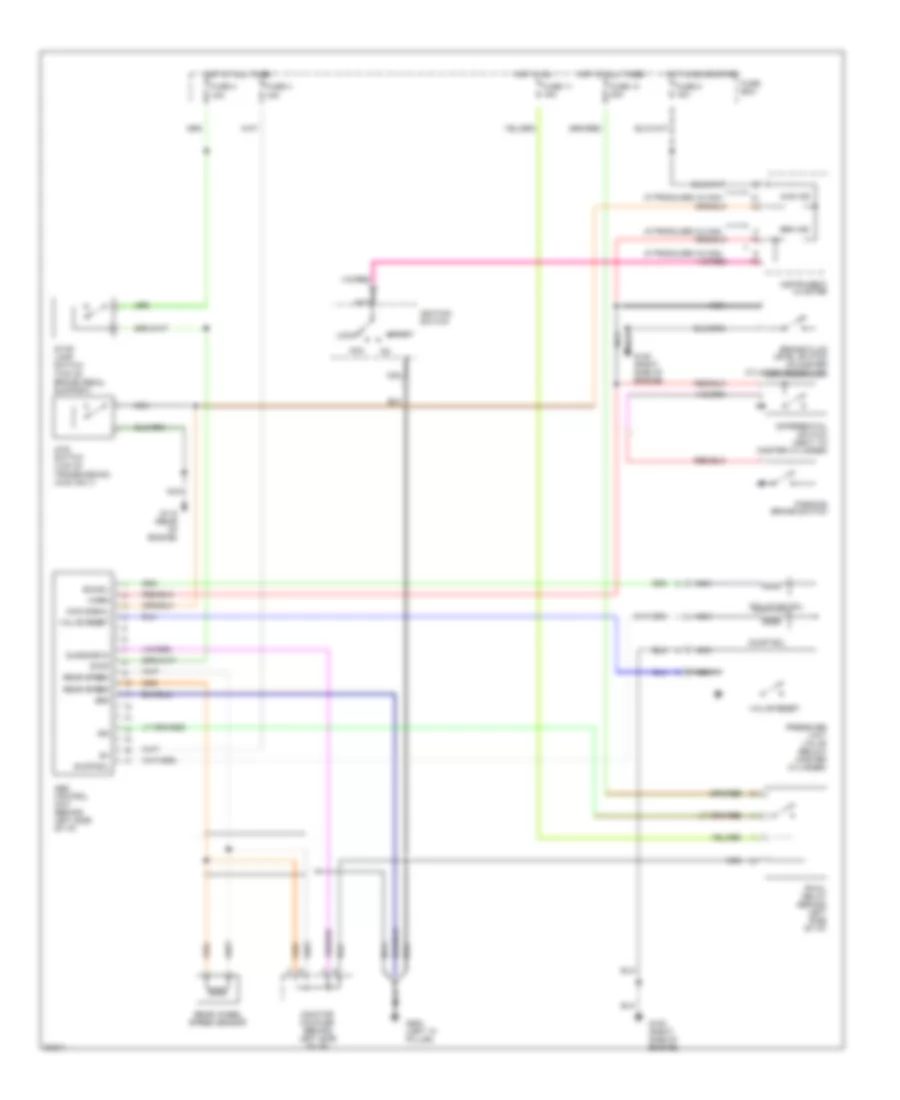
Anti-lock Brake Wiring Diagrams for Suzuki Sidekick JLX 1995
 https://portal-diagnostov.com/license.html
Automotive Electricians Portal FZCO
Automotive Electricians Portal FZCO
https://portal-diagnostov.com/license.html
https://portal-diagnostov.com/license.html
Automotive Electricians Portal FZCO
Automotive Electricians Portal FZCO
List of elements for Anti-lock Brake Wiring Diagrams for Suzuki Sidekick JLX 1995:
- (if produced in can)
- (top of brake pedal support)
- (top of transmission) (4wd only)
- 13
- 4wd ind
- 4wd signal
- 4wd switch
- Abs control unit (behind left side of i/p)
- Acc
- Brake fluid level switch (in master cylinder reservoir)
- Brk ind
- Diagnostic
- Differential switch (next to master cylinder)
- Dump sol
- Fuse 11 15a
- Fuse 13 20a
- Fuse 3 15a
- Fuse 4 15a
- Fuse 8 15a
- Fuse box
- G115 (rear of engine)
- G120 (right side of engine)
- G900 (left "a" pillar)
- Gnd
- Hot at all times
- Hot in on
- Hot in on or start
- Ign
- Ignition switch
- Instrument cluster
- Iso sol
- Isolation sol
- Lock
- Monitor coupler (behind left side of i/p)
- Nca
- Parking brake switch
- Pressure limit valve (below master cylinder)
- Rear speed
- Rear wheel speed sensor
- Rwal relay (behind left side of i/p)
- Start
- Stop
- Stop lamp switch
- Valve reset
- Warn
 Čeština
 Dansk
Dansk Deutsch
 Ελληνικά
 English
 English
 Español
 Suomi
Suomi Français
 Français
 עברית
עברית Hrvatski
 Magyar
 Italiano
 한국어
한국어 Nederlands
 Polski
 Português
 Português
 Română
 Русский
 Slovenčina
 Slovenščina
 Svenska
 Türkçe
 中文 (中国)
 日本語
日本語
