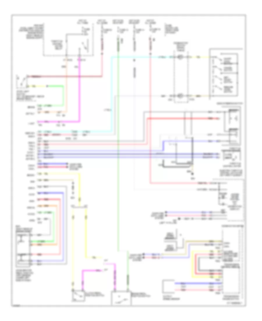
CRUISE CONTROL
Cruise Control Wiring Diagram for Nissan Xterra X 2013
 https://portal-diagnostov.com/license.html
Automotive Electricians Portal FZCO
Automotive Electricians Portal FZCO
https://portal-diagnostov.com/license.html
https://portal-diagnostov.com/license.html
Automotive Electricians Portal FZCO
Automotive Electricians Portal FZCO
List of elements for Cruise Control Wiring Diagram for Nissan Xterra X 2013:
- 42g
- 43g
- A/t
- A/t assembly
- Accelerator pedal position (app) sensor (under left side of dash)
- Aps1
- Aps2
- Ascd steering switch
- Ascd sw
- Avcc
- Avcc 1
- Avcc2
- Bncsw
- Brake
- Brake pedal position switch
- Can-h
- Can-l
- Cancel switch
- Close
- Clutch pedal position switch
- Combination meter
- Combination switch (spiral cable)
- Computer data lines system
- Cruise ind
- E119
- E122
- E16
- E160
- E2 f32
- E24
- E5 f14
- Ecm (right rear of engine compt)
- Electric throttle control actuator (on throttle body)
- F502
- F503
- F505
- F506
- F54
- Fuse 12 10a
- Fuse 14 10a
- Fuse 19 10a
- Fuse 20 10a
- Fuse 20a
- Fuse block (j/b) (right side of dash)
- Gnd
- Gnd-a
- Gnd-a2
- Hot at all times
- Hot in on or start
- Input speed sensor 1
- Input speed sensor 2
- Ipdm e/r (intelligent power distribution module engine room) (right rear of engine compt)
- M/t
- M102
- M30
- M31 e152
- M57 (left "a" pillar)
- Mot rly
- Motor 1
- Motor 2
- Nca
- On/off (main) switch
- Open
- Out spd sen gnd
- Out spd sens power out spd sen
- Output speed sensor
- Pnk
- Red
- Resume/ accel switch
- Sensor 1
- Sensor 2
- Set ind
- Set/ coast switch
- Stop light switch (a/t: on bracket, above brake pedal)
- Throttle control motor
- Throttle control motor relay
- Throttle position sensor
- Tps 1
- Tps 2
- Transmission control module
- Transmission range switch
- Unified meter control unit (w/ information display)
- V mot
 Čeština
 Dansk
Dansk Deutsch
 Ελληνικά
 English
 English
 Español
 Suomi
Suomi Français
 Français
 עברית
עברית Hrvatski
 Magyar
 Italiano
 한국어
한국어 Nederlands
 Polski
 Português
 Português
 Română
 Русский
 Slovenčina
 Slovenščina
 Svenska
 Türkçe
 中文 (中国)
 日本語
日本語
